

Page 1
2ea @3/8 x 3mm
Part Needed Quantity
Reason why ( missing, scratched, broken glass, bent, bad finish)
Comments
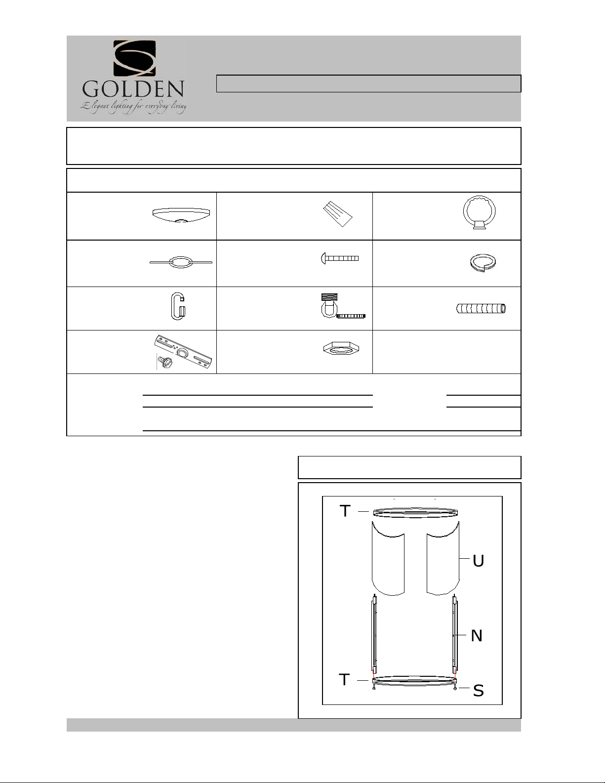
PARTS & ASSEMBLY SHEET
Notice:
For Customer Service, contact the place of purchase to arrange for replacement
Read and review installation instruction sheet
before assembling the fixtur e.
Cap (T) over the Metal Frame.
for protectio n dur i ng ins t all ati o n t o av o id i nj ur y .
Fig. 1
Company Name:_______________________ Co. Account #:___________
to be filled out by retailer
This fixture assembled PO:__________ Date: _ ____ ___
Fixture Name: Payton 1157-6P CH/AB
Please review the parts listing and check for all parts before assembling the fixture. If any parts are
missing or damaged, please note on this sheet and contact the place of purchase to arrange for replacement
parts.
PARTS LIST
Canopy Wire Connectors Top Loop
1ea D5"×H1" 3ea P4 Orange 1ea W60 x 70mm
Chain
1ea 6ft x4.2mm 2ea 8/32" x 1" 1ea @15 x 2mm
Chain
Connector
2ea @4.2X50mm 1ea @3/8 x 40mm x 5mm 1ea @3/8 x 40mm
Mounting Strap
w/ ground screw
1ea 3/4"X4"
Part Needed Quantity
Junction Box
Screw
Canopy Loop
with Collar
Hex Nut
Spring Washer
Nipple
FIXTURE ASSEMBLY INSTRUCTIONS
1157-6 CH/AB
1. Use Deco Nuts (S) to attach Circular End
Cap (T) to Metal Frame (N).
2. Carefully slide Glass Panels (U) into Metal
Frame (N). Then, lower the other Circular End
Note:Glass edge s m ay be sharp. Wear glove s
If the glass can not be successfully placed into
the framework, please relax and adjust the iron
bar slightly. It is s ugge s t e d that thi s be
completed by two people.
Page 2
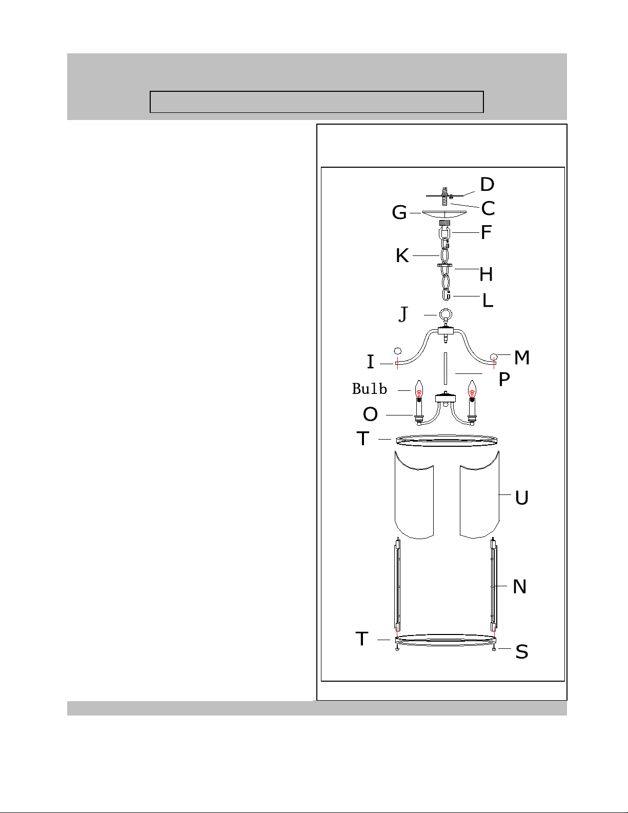
Fig. 2
For Customer Service, contact the place of purchase to arrange for replacement parts.
PARTS & ASSEMBLY SHEET
Fixture Name: Payton 1157-6P CH/A B
ASSEMBLING THE F IXT U RE (Fig. 2)
3. Thread Threaded Stem (P) into the coupling at
centre of Fixture Body (O).
4. Thread the Top Loop (J) onto Stem (I) and (P).
Hand-tighten until snug.
5. Lower the fixture over the glass cage, use the
round Deco Nuts (M) to secure Arms (L) t o th e
cage (N).
6. Measure to determine the correct number of
links needed for the proper hanging height. Use a
pair of pliers to open one link of Chain (K). Then,
7. Slip Canopy loop collar (H) over the chain, then do the
remove and discard the excess Chain.
same with the canopy (G).
7. Use one Chain Connector (L) to attach one end
8. When ready to complete the installation Use the other
of the chain to Top Loop (J) and close the chain
chain connector and attach the other end of the chain to
connector.
the canopy loop (F) and close the chain connector.
8. Feed the fixture wires through the chain (every
9. Make sure the weight of the chandelier will be
three links) and pull the wires until taut.
supported by the chain-not the electrical wire.
9. Slip Canopy Loop Collar (H) over the chain, then
* You may now install t he fixture.
do the same with Canopy (G).
10. To complete the installation, use the other
chain connector and attach the other end of the
chain to the Canopy Loop (F) and close the chain
connector.
11. Make sure the weight of the chandelier will be
supported by the chain, not the electrical wire.
* You may now install the fixture.
Note: Complete these remaining steps after the
fixture is hung.
12. Install the light bulbs (not provided) in
accordance with the fixture's specifications.
(DO NOT EXCEED MAXIMUM WATTAGE RATING)
13. Carefully press the clips inside of Shade (Q)
onto the bulb.
Page 3

INSTALLATION INSTRUCTIONS
7. Unscrew Canopy Loop Collar (H ) from the canopy loop.
should be exposed. Adjust until desired height is reached. *The
the wiring connections.
CONNECTING THE WIRES (Fig 2)
connecting BLACK to BLACK (or SMOOTH) and WHITE to WHITE (
Fig. 2
WARNING! SHUT OFF POWER AT FUSE OR CIRCUIT BREAKER.
13. Raise Canopy (G) to the ceiling and secure in place by
HANGING THE FIXTURE (Fig.1)
2. Shut off the power at the circuit breaker and remove the old
Fig. 1
Fixture Name: Payton 1157-6/4/3P CH/AB
1. Carefully remove the new fixture from the carton and the
yellow bag that holds all parts. Check that all parts are
included as shown in the illustration and Parts List.
fixture from the ceiling, including the old mounting strap.
3. Thread Nipple (C) into Canopy Loop (F) until snug.
4. Thread the other end of Nipple (C) with the canopy loop
attached into Mounting Strap (D).
5. Place Lock Washer (B) over end of Nipple (C) which should
protrude through Mounting Strap (D) and thread Hex Nuts (A)
onto Nipple until tight.
6. Take this mounting strap assembly and mount to ceiling
junction box with junction box Screws (E). Tighten the screws
securely with a screw driver.
For Chandelier Light Fixture
Take the canopy and pass over the canopy loop.
Approximately one half of the canopy loop exterior threads
canopy loop collar should fit snugly on the canopy loop after
the canopy is installed. Remove canopy and canopy lock
collar.
8. Assemble the fixture and have an assistant or a secure
support to hold the weight of the fixture while you complete
9.Thread the fixture wires and ground wire of the assembled
fixture through the canopy loop and nipple and into the outlet
box.
10. Attach the power supply wires to the fixture lead wires by
or RIBBED) .
11. Ground wire connection: Connect the fixture ground wire
to house ground wire, which us u ally has green or copper
insulation, with the correct size of wire connector. If there is no
house ground wire at ceiling junction box then attach fixture
ground wire securely onto green grounding screw located on
the mounting bar.
NOTE: Twist the wires together in the same direction that you
twisted the wire connector onto the wires.
12. Tuck the wire connections into the Junction Box.
tightening the Canopy Loop Collar (H) into the Canopy Loop
(F)
14. Install the light bulbs and glass shade as per the fixture
assembly sheet.
For Customer Service, contact the place of purchase to arrange for replacement parts.
YOUR INSTALLATION IS NOW COMPLETE. RETURN
POWER TO THE JUNCTIO N BO X AND TEST T HE
FIXTURE.
 Loading...