

Page 1
y
PARTS & ASSEMBLY SHEET
Fixture Name: Cerchi 1030-WSC CH
This fixture assembled PO:__________ Date: ________
Notice: Please review the parts listing and check for all parts before assembling the fixture. If any parts are
missing or damaged, please note onthis sheet and contact the place of purchase to arrange for replacement
parts.
Company Name:_______________________Co. Account #:_____________
PARTS LIST
below to be filled out by retailer
Mounting Strap 1ea
Wire Connnector 3ea Hex Nut 2ea
Green Ground
Screw
Part Needed Quantity
Part Needed Quantity
Reason wh
Comments
FIXTURE ASSEMBLY INSTRUCTIONS
Read and review installation instruction sheet before
assembling the fixture.
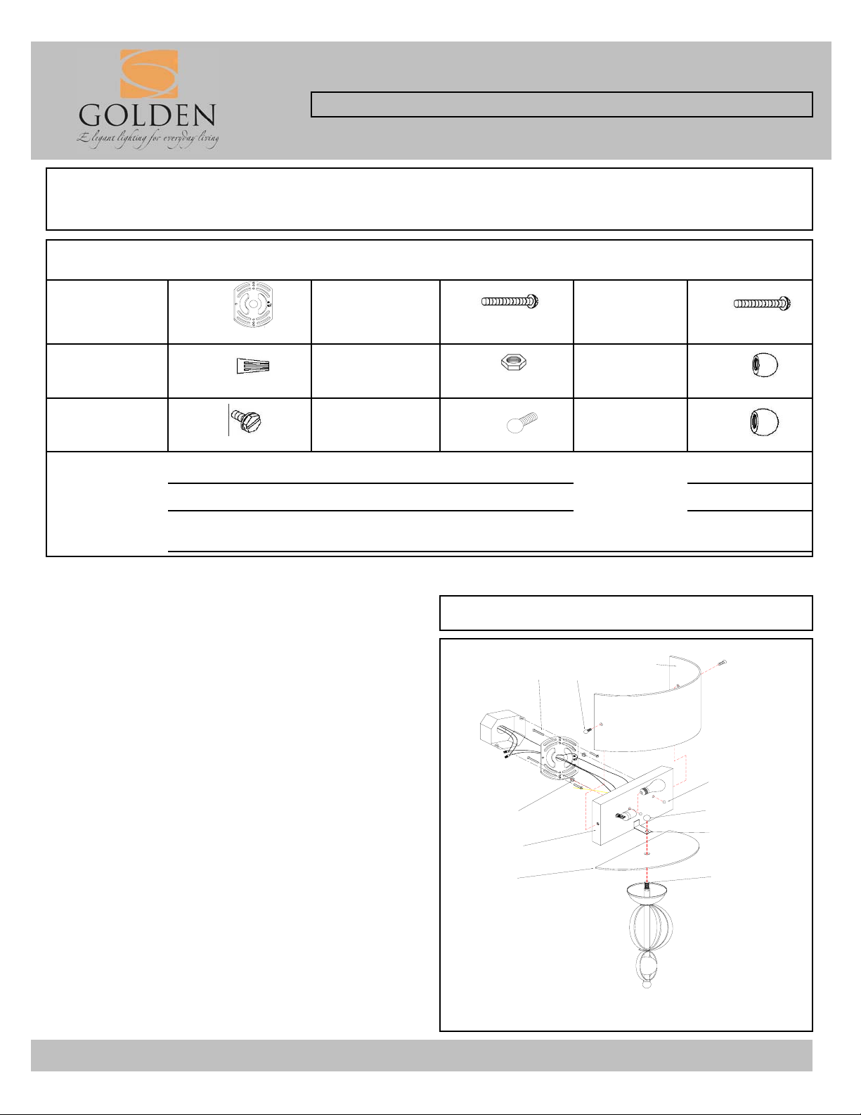
ASSEMBLING THE FIXTURE (Fig.1)
1. Attach Bottom Panel (I) to bottom of Back Plate (H) and
1ea Shade Screw 2ea Finial 1ea
( missing, scratched, broken glass, bent, bad finish)
Junction Box
Screw
2ea Mounting Screw 2ea
Deco Nut
(round nut)
1030-WSC CH
Fig. 1
B
M
N
2ea
slide Column Nipple (J) through Bottom Panel (I) and Bracket
(L). Fasten in place with Finial (K), tighten until snug.
* You may now install the fixture.
2. Install light bulb in accordance with the fixture's
specifications.
3. Secure the Shade (N) to Back Plate (H) with Shade
Screws (M).
(DO NOT EXCEED THE MAXIMUM WATTAGE RATING!)
NOTE: INSTALL THE GLASS ASSEMBLY AFTER
THE FIXTURE IS HUNG.
For Customer Service, contact the place of purchase to arrange for replacement parts.
A
H
I
O
K
L
J
Page 2
INSTALLATION INSTRUCTIONS
r
Fixture Name: Cerchi 1030-WSC CH
For Wall Mount Light Fixture
WARNING ! SHUT OFF POWER AT FUSE OR CIRCUIT BREAKER.
HANGING THE FIXTURE (Fig.1)
1. Carefully remove the new fixture from the carton and the yellow
bag that holes all your parts. Check that all parts are included as
shown in the illustration and parts list.
2. Shut off power at the circuit breaker and remove the old fixture
from wall, including the old mounting strap.
3. The Mounting Strap (A) contains several pairs of threaded
holes, find the pair of holes that match the holes spacing in your
fixture Back plate (H) and thread the two Mounting screws (B) half
way into the Mounting strap (A).
4. Place the Mounting strap (A)over the Junction Box so the
Mounting screws (B) are vertical or horizontal, as required by
fixture type.
5. Attach the Mounting strap (A) to the Junction box using the two
Mounting screws (D). Tighten the screws (D) securely with screw d
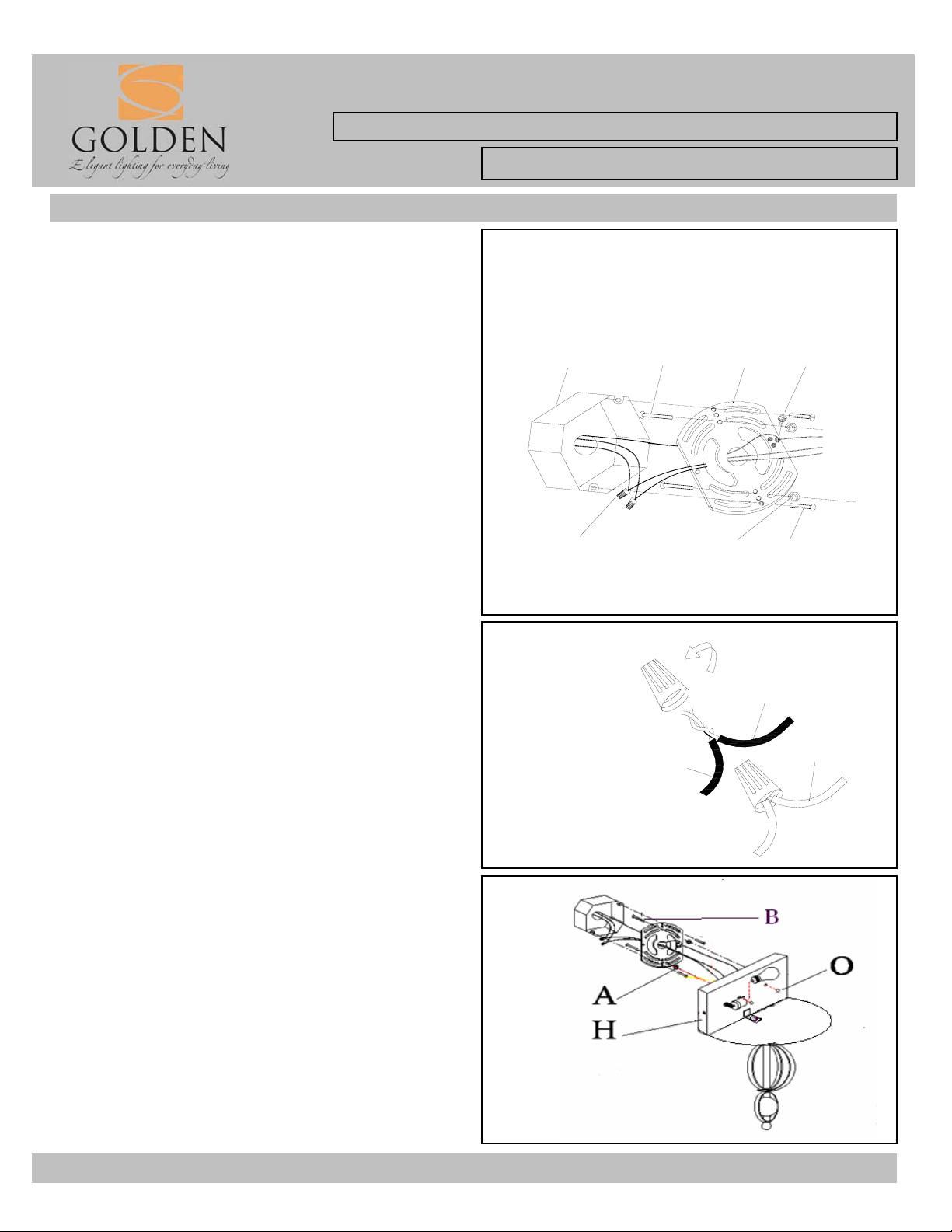
CONNECTING THE WIRES (Fig 2)
6. Attach the power supply wires to the fixture lead wires by
connecting BLACK to BLACK (or SMOOTH) and WHITE to
WHITE (or RIBBED).
7. Attach the GROUND wire(GREEN or COPPER) from the
Junction Box and the fixture Ground wire to the green Ground
Screw on the Mounting Bracket (A) or connect both wires together
using the correct size of wire connectors.
NOTE: Twist the wires together in the same direction you twist the
wire connector onto the wires.
8. Tuck these wire connections neatly into the Junction Box.
Fig. 1
JUNCTION BOX
E
G
Fig. 2
FIXTURE WIRES
SMOOTH (BLACK)
B
C
RIBBED (WHITE)
A
F
D
HOUSE WIRES
BLACK
WHITE
FINISHING THE INSTALLATION (Fig.3)
9. Place the fixture Back Plate ( H ), over the Mounting Screws(B),
so it protrude through the holes in the Back Plate ( H ).
10. Thread the Deco Nuts (O ) onto the Mounting Screws (B) and
continue turning until the Back Plate (H) is snug against the wall.
11. Install the light bulb and shade as per the fixture assembly
sheet.
YOUR INSTALLATION IS NOW COMPLETE. RETURN POWER
TO THE JUNCTION BOX AND TEST THE FIXTURE.
For Customer Service, contact the place of purchase to arrange for replacement parts.
Fig. 3
 Loading...