

Golden engineering XRS4 Operator's Manual


TABLE OF CONTENTS
PAG E
1.0 INTRODUCTION 2
2.0 WARNINGS 2
ELEVATION WARNING 2
DUTY CYCLE 2
3.0 PHYSICAL DESCRIPTION 3
HIGH VOLTAGE PULSER/TUBEHEAD 3
BASE 3
BATTERY PACK 3
BATTERY CHARGER 3
CONTROLS 4
CABLE CONNECTOR DIAGRAM 5
4.0 DESCRIPTION OF OPERATION 6
BLOCK DIAGRAM 6
5.0 OPERATION INSTRUCTIONS 7
OPERATING PRECAUTIONS 8
EXCLUSION ZONE 8
SUGGESTED PULSE SETTINGS 9
NAVIGATING THE MENU 10
SET PULSE COUNT 11
TIME DELAY OPTION 12
MULTIPLE PULSE TRAIN OPTION 13
DUTY CYCLE 14
PULSE SETTINGS 14
6.0 MAINTENANCE 15
DOSE MEASUREMENT 15
TUBE REPLACEMENT 15
7.0 TROUBLE-SHOOTING 15
8.0 INSTRUCTIONS FOR REPAIR 16
FUSE REPLACEMENT 16
REMOVING BOARDS 17
BOARD INSTALLATION 17
STORAGE, TRANSPORT, DISPOSAL 17
9.0 WARRANTY 18
MANUFACTURER & EUROPEAN REPRESENTATIVE 18
RETURNING REPAIR INSTRUCTIONS 18
10.0 SPECIFICATIONS 19
PHYSICAL DIMENSIONS 19
X-RAY OUTPUT 19
ELECTRICAL & THERMAL CHARACTERISTICS 19
11.0 SPARE PARTS 19
1
1.0 INTRODUCTION
The XRS4 produces high levels of radiation and must be operated by qualied personnel who have read
The XRS4 is an industrial type open beam X-ray generator intended to radiograph inanimate objects. The XRS4 is
a pulsed X-ray device that produces X-ray pulses of very short duration (10 nanoseconds). The energy produced
by the XRS4 is up to 370kVp, which makes it possible to radiograph up to one (1.5) inch (3.81 cm) of steel.
XRS4 standard accessories are two keys, two battery packs, and one battery charger. Remote cable, carrying case,
and lm developing equipment are also common accessories.
the Warning and Operations section of the manual before operating the device.
2.0 WARNINGS
The XRS4 is a pulsed X-ray generator that emits hazardous ionizing radiation when pulsing. The XRS4 should only
be operated by authorized personnel who are properly trained to safely operate the generator. The XRS4 must
be registered with proper authorities prior to use and should not be used to intentionally expose humans.
Develop and closely follow a safe operating system for using the XRS4. The safe operating system must ensure that
no one is exposed to radiation above the permissible limits which are 2 mR (0.02 mSv) per hour for a member of
the public. The safe operating system must ensure the XRS4 is used within federal and state guidelines.
All operators and users of the XRS4 X-ray machine must wear a personal radiation monitoring device, such as a
TLD (thermo luminescent dosimeter), lm badge, and/or a pocket dosimeter consistent with the appropriate federal, territorial or provincial standards (note: an electronic dosimeter will not detect the XRS4 radiation pulses). If
an operator or bystander is exposed to an unacceptable level of radiation contact your Radiation Safety Ofcer
and/or appropriate health care provider.
Due to the short pulse width of the XRS4, survey meters of the Geiger-Mueller and scintillator type do not accurately detect the radiation emitted from the X-ray source.
Survey meters should be of the ionization type and should be used in the integration mode. Survey meters must not
be used in the rate mode because the XRS4 does not produce constant radiation. The XRS4 produces very high
rates of radiation for very short periods of time resulting in either unrealistically high readings or no readings for
a survey meter in rate mode.
The XRS4 has no explosion proof rating and should not be used in an explosive atmosphere. The Spark Gap
is vented to the air and could be a source of ignition. THE STANDARD XRS4 WITHOUT A MODIFIED SPARK
GAP WILLL LIKELY FAIL PREMATURELY WHEN USED ABOVE 5000 ft. (1524 m) ELEVATION.
DUTY CYCLE WARNING. The XRS4 is a light duty machine that is not made to pulse continuously. The maximum
duty cycle for the XRS4 is 200 pulses every four minutes (3000 pulses per hour). Additional 30 second rest every
50 pulses is suggested for applications requiring more than one hour continual use or in temperatures exceeding
90 degrees F. Exceeding the duty cycle will shorten the life of the tube and head.
2

3.0 PHYSICAL DESCRIPTION
BEAM ANGLE
LABEL
COLLIMATOR
HEAD
HANDLE
RADIATION
WARNING LABEL
TOUCH PAD KEY
BATTERY
HOUSING
HIGH VOLTAGE PULSER/TUBEHEAD. The main body of the XRS4 is the tube head which contains the tube cavity,
cold cathode type X-ray tube, spark gap, high voltage capacitor, and transformer. The standard collimator located on the front of the head limits the X-ray beam to 40 degrees. Special order collimators up to 85 degrees are
available.
BASE. The base of the XRS4 contains the identication label and a threaded ¼-20 insert that can be attached to
any standard camera tripod. Identication label indicates the model, manufacturer, and serial number is located
on the bottom of the XRS4 base.
BATTERY PACK. The standard battery pack is a DeWalt® 18V nickel-cadmium battery. Optional battery chem-
istry or voltage may be available.
BATTERY CHARGER: The standard battery charger is the DeWalt® DW9116 110V charger or DE9108 220V
charger. Battery charge time is one hour. See battery charger manual for additional instructions and warnings.
3
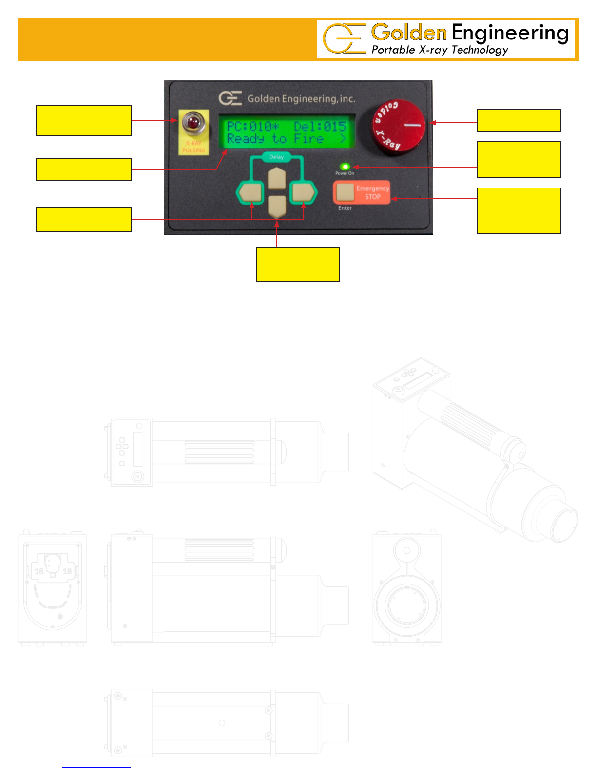
CONTROLS
X-RAY PULSING
LIGHTS
LCD
DELAY SWITCH
DIRECTIONAL
ARROWS
RED X-RAY PULSING LIGHT:
¾ Blinks after time delay button or remote cable button is pressed AND between multiple pulse trains.
¾ Stays on continuously while the XRS4 pulses.
¾ Blinks at a slower rate between multiple pulse trains.
¾ This is a failsafe warning light. If the light does not work the X-ray unit will not pulse.
KEY
POWER ON
LIGHT
ENTER /
EMERGENCY
STOP
LIQUID CRYSTAL DISPLAY (LCD): 32 character LCD. Home screen displays Pulse count (PC), Multiple pulse
trains (*), Time Delay (DEL), and Ready to Fire. See instructions for menu options.
DELAY SWITCH: Initiates time delay mode count down when left and right arrows pressed simultaneously.
POWER ON LIGHT: Illuminates when battery voltage is applied to control module.
ENTER/ EMERGENCY STOP SWITCH: ENTER used when menu options are selected.
EMERGENCY STOP stops the unit during delay count down mode or between multiple pulse trains.
DIRECTIONAL ARROWS: Left, Right, Up, Down used to navigate through LCD and menu options.
4
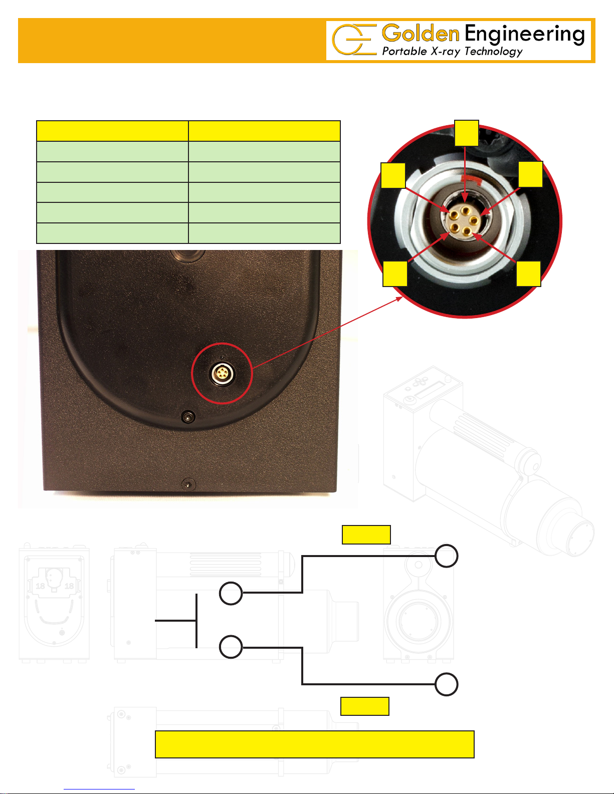
XRS4 REAR VIEW/CABLE CONNECTOR
CABLE CONNECTOR: Lemo “K” series ve pin connector located on the back of the control module beneath the
battery receives the remote cable or imaging system cable.
PIN # DESCRIPTION
1 +5 VOLTS 100 ma MAXIMUM
2 REMOTE SWITCH
3 REMOTE SWITCH - NO DELAY
4 X-RAY ON SIGNAL
5 COMMON 0 VOLTS
1
2
3 4
Remote cable connector
5
REMOTE CONNECTOR: LEMO EPG.0B.305.HLN
MATING CABLE PLUG: LEMO FGG.0B.305.CLAD 56Z
PIN 2
PIN 5
Remote switch inputs are activated when grounded.
5
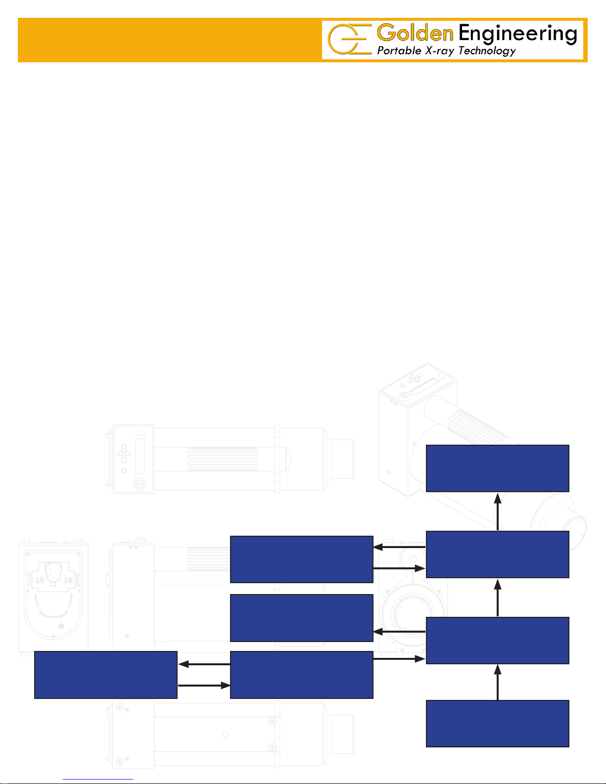
4.0 DESCRIPTION OF OPERATION
The block diagram below illustrates how the XRS4 functions. The following sequence of events takes place each
time the XRS4 is red:
1. User initiates operation of the machine.
2. The control section sends a signal to the converter section to begin oscillating.
3. Once oscillating, the converter section changes the 18 volts DC to 22Khz AC.
4. The transformer charges the High Voltage Capacitor to about 10,000 volts.
5. The spark gap arcs after the High Voltage Capacitor reaches proper voltage.
6. The pulse detector signals the control block that the unit has pulsed.
7. As the High Voltage Switch is closed, a high voltage transient of approximately 370,000 volts and
10 nanoseconds in duration is applied across the X-ray tube generating X-rays.
The closing of the High Voltage Switch produces an audible pulsing sound. The XRS4 cannot produce x-rays with-
out the pulsing sound so it serves as an additional warning the XRS4 is functioning.
This unit generates X-rays through high voltage bombardment of a tungsten target. The XRS4 does not contain radioactive materials. All the high voltage is contained within the aluminum canister and as long as the canister is not
punctured the operator is not exposed to dangerous voltages.
USER INTERFACE
BLOCK DIAGRAM
SPARK GAP
PULSE DETECTOR
CONTROLLER
X-RAY TUBE
HIGH VOLTAGE
CAPACITOR
CONVERTER
6
BATTERY
 Loading...