

Golden engineering XRS-3 Operator's Manual

XRS-3
X-RAY SOURCE
OPERATOR’S MANUAL

- 1 -
CONTENTS
ITEM PAGE
1.0 INTRODUCTION................................................................................. 2
2.0 WARNINGS......................................................................................... 2
DUTY CYCLE……………………………………………………………. 2
3.0 PHYSICAL DESCRIPTION................................................................. 3
HIGH VOLTAGE PULSER/TUBEHEAD....................................…….. 3
BASE.................................................................................................. 3
BATTERY PACK……........................................................................ 3
BATTERY CHARGER........................................................................ 3
CONTROL MODULE…………………………..................................... 4
CABLE CONNECTOR DIAGRAM………………………………………. 5
4.0 DESCRIPTION OF OPERATION........................................................ 6
BLOCK DIAGRAM………………………………………………………… 6
5.0 OPERATING INSTRUCTIONS............................................................ 7
OPERATING PRECAUTIONS.........................................................…. 7
EXCLUSION ZONE………………………………………………………. 7
PULSE SELECTION …………………………………………………….. 7
REMOTE CABLE OPTION……………………………………………… 8
DELAY MODE OPTION…………………………………………............ 8
REAL TIME IMAGING OPTION………………………………………… 8
PULSE SETTINGS............................................................................. 8
6.0 SOFTWARE........................................................................................ 9
7.0 MAINTENANCE.................................................................................. 9
DOSE MEASUREMENT…………………….…………………………. 9
TUBE REPLACEMENT………………………………………………... 9
8.0 TROUBLE-SHOOTING....................................................................... 10
9.0 INSTRUCTIONS FOR REPAIR......................................................... 10
HANDLE REPLACEMENT…………………………………………… 10
FUSE REPLACEMENT………………………………………………. 11
REMOVING BOARDS………………………………………………… 11
BOARD INSTALLATION……………………………………………… 11
HEAD REPLACEMENT………………………………………………. 12
BATTERY DISPOSAL………………………………………………… 12
10.0 WARRANTY...................................................................................... 13
RETURNING REPAIR INSTRUCTIONS ……………………………. 13
11.0 SPECIFICATIONS............................................................................. 14
PHYSICAL DIMENSIONS................................................................ 14
X-RAY OUTPUT............................................................................... 14
ELECTRICAL & THERMAL CHARACTERISTICS…...................…. 14
12.0 SPARE PARTS………………………………………………………… 14

1.0 INTRODUCTION
The XRS-3 produces high levels of radiation and must be operated by qualified personnel who
have read the Warning and Operations section of the manual before operating the device.
The XRS-3 is a small, lightweight x-ray generator that operates on its own removable battery pack. The
XRS-3 is a pulsed x-ray device that produces x-ray pulses of very short duration (50 nanoseconds). It
produces a relatively low dose rate comparable to a 0.25 ma constant potential machine. The energy
produced by the XRS-3 is up to 270KVP, which makes it possible to radiograph up to one (1) inch (2.54
cm) of steel.
XRS-3 standard accessories are two keys, two battery packs, and one battery charger. Remote cable,
carrying case, and film developing equipment are also common accessories.
2.0 WARNINGS
The XRS-3 is a pulsed X-ray generator that emits hazardous ionizing radiation when pulsing. The XRS-3
should only be operated by authorized personnel who are properly trained to safely operate the
generator. The XRS-3 must be registered with proper authorities prior to use and should not be used to
intentionally expose humans.
Develop and closely follow a safe operating system for using the XRS-3. The safe operating system
must ensure that no one is exposed to radiation above the permissible limits which are 2 mR (0.02 mSv)
per hour for a member of the public. The safe operating system must ensure the XRS-3 is used
within federal and state guidelines.
All operators and users of the XRS-3 x-ray machine must wear a personal radiation monitoring device,
such as a TLD (thermoluminescent dosimeter), film badge, and/or a pocket dosimeter consistent with
the appropriate federal, territorial or provincial standards (note: an electronic dosimeter will not
detect the XRS-3 radiation pulses).
Due to the short pulse width of the XRS-3, survey meters of the Geiger-Mueller and scintillator type do
not accurately detect the radiation emitted from the x-ray source.
Survey meters should be of the ionization type and should be used in the integration mode.
Survey meters must not be used in the rate mode because the XRS-3 does not produce constant
radiation. The XRS-3 produces very high rates of radiation for very short periods of time resulting in
either unrealistically high readings or no readings for a survey meter in rate mode.
The XRS-3 has no explosion proof rating and should not be used in an explosive atmosphere.
The Spark Gap is vented to the air and could be a source of ignition.
DUTY CYCLE WARNING. The XRS-3 is a light duty machine that is not made to pulse
continuously. The maximum duty cycle for the XRS-3 is 200 pulses every four minutes (3000 pulses
per hour). Two consecutive pulse trains of 99 pulses can be fired then the unit should rest at least four
minutes. Exceeding the duty cycle will shorten the life of the tube and head.
3
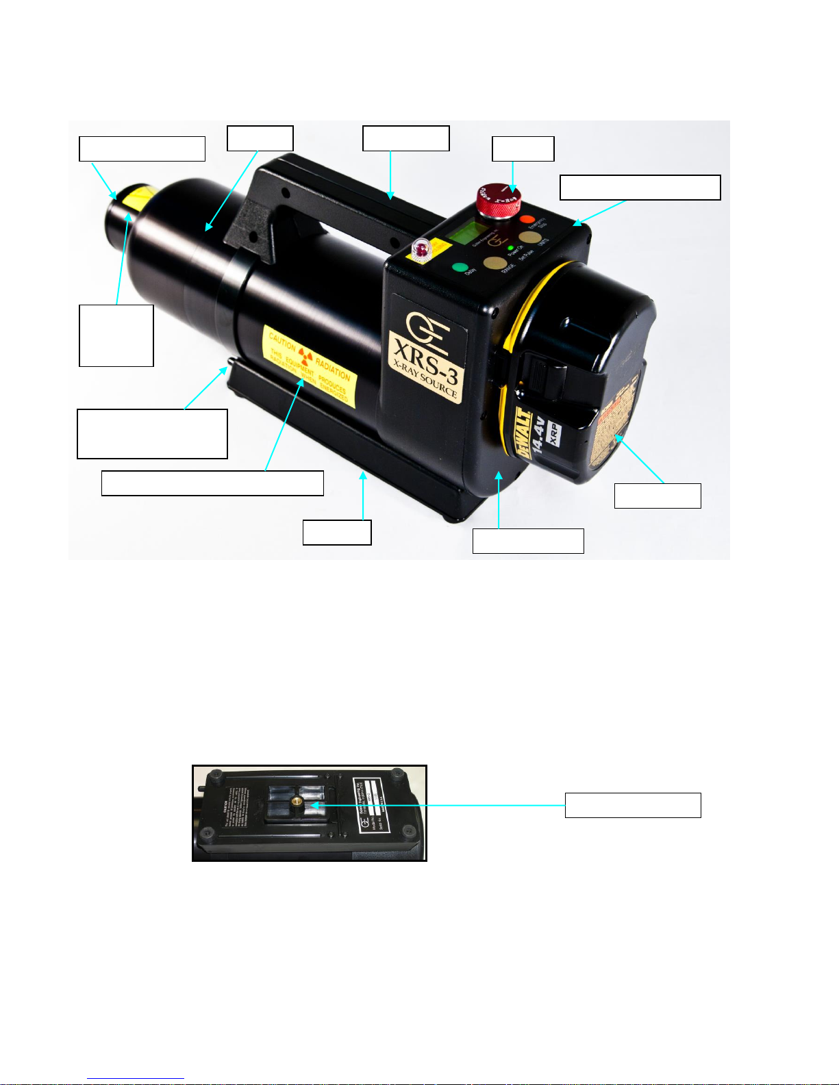
3.0 PHYSICAL DESCRIPTION
Figure 1: XRS-3 X-ray Unit
HIGH VOLTAGE PULSER/TUBEHEAD. The main body of the XRS-3 is the tube head which contains
the tube cavity, cold cathode type X-ray tube, spark gap, high voltage capacitor, and transformer. The
standard collimator located on the front of the head limits the X-ray beam to 40 degrees. Special order
collimators up to 85 degrees are available.
BASE. The base of the XRS-3 contains the base plate, tripod mount, tripod mount release button, and
identification label. The tripod mount contains threaded ¼-20 insert that can be attached to any standard
camera tripod. Press the release button to remove the tripod mount from the base. A label identifying
the model, manufacturer, and serial number is located on the bottom of the XRS-3 base.
Figure 2: Base
BATTERY PACK. The standard battery pack is a DeWalt 14.4V nickel-cadmium battery. Optional
battery chemistry or voltage may be available.
BATTERY CHARGER: The standard battery charger is the DeWalt DW9116 110V charger or DE9108
220V charger. Battery charge time is one hour. See battery charger manual for additional instructions
and warnings.
BATTERY
CONTROL MODULE
HANDLE
BASE
TRIPOD MOUNT
RELEASE BUTTON
HEAD
COLLIMATOR
KEY
BEAM
ANGLE
LABEL
RADIATION WARNING LABEL
BACK PLATE
TRIPOD MOUNT
4
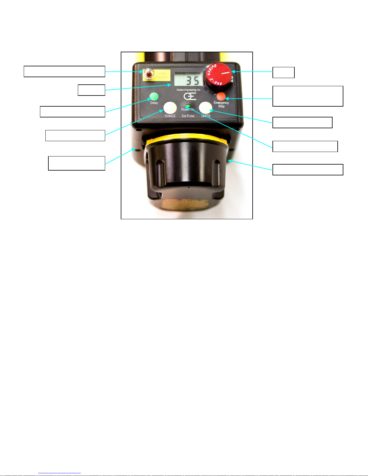
3.5 CONTROL MODULE
Figure 3: Control Module
POWER ON LIGHT: Illuminates when battery voltage is applied to control module.
RED X-RAY PULSING LIGHT: Blinks after time delay button or remote cable button is pressed to warn
that the XRS-3 is going to pulse. The light stays on continuously while the XRS-3 is pulsing. This is a
failsafe warning light. If the light does not work the X-ray unit will not pulse.
LIQUID CRYSTAL DISPLAY (LCD): Two digit LCD displays selected pulse, time before unit pulses,
software version, and total number of pulses on the unit.
RANGE SWITCH: Used to alternate LCD between tens digit and ones digit.
UNITS SWITCH: Used to change the value of the tens digit or units digit from 0 to 9. The UNITS
SWITCH is also used with the EMERGENCY STOP SWITCH to alter the default pulse setting.
DELAY SWITCH: Initiates delay mode.
EMERGENCY STOP SWITCH: Stops the unit before it begins pulsing or stops the unit in the middle of a
pulse train. This switch can also be pressed with the UNITS SWITCH to alter the default pulse setting
when the XRS-3 is first powered up.
CABLE CONNECTOR: Lemo connector located on the back of the control module beneath the battery
receives the remote cable or imaging system cable. See Rear View Diagram on page 5 for details.
BACK PLATE: Covers the Oscillator board and contains battery terminal connectors.
UNITS SWITCH
DELAY SWITCH
RANGE SWITCH
LCD
X-RAY PULSING LIGHT
KEY
EMERGENCY STOP \
PULSE DEFAULT
POWER ON LIGHT
CABLE CONNECTOR
BACK PLATE
 Loading...