

Golden engineering XR150 Operator's Manual

OPERATOR'S MANUAL
MARCH 2018
- Golden Engineering
�- Portable X-ray Technology

TABLE OF CONTENTS
PAGE
1.0 INTRODUCTION 2
2.0 WARNINGS 2
DUTY CYCLE 2
3.0 PHYSICAL DESCRIPTION 3
HIGH VOLTAGE PULSER/TUBEHEAD 3
HOUSING 3
HANDLE 3
BATTERY PACK 3
BATTERY CHARGER 3
REAR VIEW 3
CONTROLS 4
CABLE CONNECTOR DIAGRAM 5
4.0 DESCRIPTION OF OPERATION 6
BLOCK DIAGRAM 6
5.0 OPERATING INSTRUCTIONS 7
OPERATING PRECAUTIONS 8
EXCLUSION ZONE 8
NAVIGATING THE MENU 9
MAIN MENU 10
SET COUNTS/PULSES 11
PULSE COUNT EXCEED DUTY CYCLE 12
SET DELAY TIME 14
SET MULTIPLE PULSE TRAINS 15
MULTIPLE PULSE TRAINS EXCEED DUTY CYCLE 16
PULSE COUNTER/LIFETIME PULSE COUNT 17
BACKLIGHT ON/OFF 18
PULSE/COUNTS MODE CHANGE 19
VOID WARRANTY INDICATOR 20
GENERATOR IDENTIFICATION NUMBERS 21
ERROR MESSAGES 22
SUGGESTED PULSE SETTINGS 23
6.0 MAINTENANCE 23
7.0 TROUBLE-SHOOTING 23
8.0 INSTRUCTIONS FOR REPAIR 24
STORAGE, TRANSPORT, DISPOSAL 24
9.0 WARRANTY 24
MANUFACTURER 24
10.0 CE CERTIFICATE 25
11.0 SPECIFICATIONS 26
PHYSICAL DIMENSIONS 26
X-RAY OUTPUT 26
ELECTRICAL & THERMAL CHARACTERISTICS 26
12.0 SPARE PARTS 26
1
1.0 INTRODUCTION
The XR150 produces high levels of radiation and must be operated by quali ed personnel who have read the
WARNINGS and OPERATING INSTRUCTIONS sections of the manual before operating the device.
The XR150 is an industrial type open beam x-ray generator intended to radiograph inanimate objects. The XR150
is a pulsed x-ray device that produces x-ray pulses of very short duration (30 nanoseconds). The energy produced
by the XR150 is up to 150kVp, which makes it possible to radiograph up to one half (0.5) inch (1.27 cm) of steel.
XR150 standard accessories are two keys, two 12V (or 10.8V) battery packs, and one battery charger. Remote
cable, carrying case are also common accessories.
2.0 WARNINGS
The XR150 is a pulsed X-ray generator that emits hazardous ionizing radiation when pulsing. The XR150 should
only be operated by authorized personnel who are properly trained to safely operate the generator. The XR150
must be registered with proper authorities prior to use and should not be used to intentionally expose humans.
Develop and closely follow a safe operating system for using the XR150. The safe operating system must ensure
that no one is exposed to radiation above the permissible limits which are 2 mR (0.02 mSv) per hour for a member
of the public. The safe operating system must ensure the XR150 is used within federal and state guidelines.
All operators and users of the XR150 x-ray machine must wear a personal radiation monitoring device, such as
a TLD (thermoluminescent dosimeter), lm badge, and/or a pocket dosimeter consistent with the appropriate
federal, territorial or provincial standards (note: an electronic dosimeter will not detect the XR150 radiation
pulses). If an operator or bystander is exposed to an unacceptable level of radiation contact your Radiation
Safety Of cer and/or appropriate health care provider.
Due to the short pulse width of the XR150, survey meters of the Geiger-Mueller and scintillator type do not
accurately detect the radiation emitted from the x-ray source.
Survey meters should be of the ionization type and should be used in the integration mode. Survey meters must not
be used in the rate mode because the XR150 does not produce constant radiation. The XR150 produces very high
rates of radiation for very short periods of time resulting in either unrealistically high readings or no readings for
a survey meter in rate mode.
The XR150 has no explosion proof rating and should not be used in an explosive atmosphere. The Spark Gap
is vented to the air and could be a source of ignition.
DUTY CYCLE WARNING
The XR150 is a light duty machine that is not made to pulse continuously. The maximum duty cycle for the XR150
is 100 counts (300 pulses) every four minutes (1500 counts/4500 pulses per hour). Exceeding the duty cycle
will shorten the life of the tube and head. In temperatures above 90 °F (32.22 °C) or continual use, rest 30
seconds after every 50 pulses and 4 minutes after every 200 pulses.
2
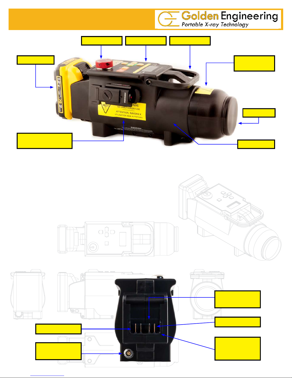
3.0 PHYSICAL DESCRIPTION
HANDLETOUCH PADKEY
BATTERY
RADIATION
WARNING LABEL HOUSING
HIGH VOLTAGE PULSER/TUBEHEAD The XR150 high voltage head which contains the cold cathode type X-ray
tube, spark gap, high voltage capacitor, transformer, and 40 degree collimator.
HOUSING The XR150 housing encloses the electronics and most of the high voltage head. The housing includes the
touchpad interface, key switch, battery terminal block, cable connector, ¼-20 threaded tripod insert, and several
tie off points that accommodate a variety of fasteners.
BEAM ANGLE
LABEL
HEAD
HANDLE Handle is attached to the left and right side of the housing adjacent to the LCD. The handle can be
removed using a T10 Torx driver.
BATTERY PACK The standard battery pack is a DeWalt® DCB127 Lithium Ion battery pack. In the USA
the DCB127 battery is rated as a 12V battery. Outside the USA the DCB127 battery maybe rated as a 10.8V
or 12V battery pack.
BATTERY CHARGER The standard battery charger is the DeWalt® DCB107 charger. DCB115
fast charger or DCB109 Car Charger are optional. Battery charge time is less than one hour with the standard
charger. See battery charger manual for additional instructions and warnings.
REAR VIEW
TEMPERATURE
SENSOR
POSITIVE +
NEGATIVE -
BATTERY
REMOTE CABLE
CONNECTOR
TERMINAL
BLOCK
3
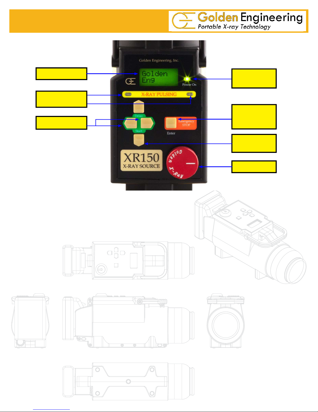
CONTROLS
LCD
POWER ON
LIGHT
X-RAY PULSING
LIGHTS
ENTER /
EMERGENCY
DELAY SWITCH
STOP
DIRECTIONAL
ARROWS
KEY
X-RAY PULSING LIGHTS:
Blink after time delay button or remote cable button is pressed AND between multiple pulse trains.
Stay on continuously while the XR150 pulses.
Blink at a slower rate between multiple pulse trains.
LIQUID CRYSTAL DISPLAY (LCD): 16-character LCD. Home screen displays counts/pulses (C or P), number of
pulse trains (if multiple pulse trains are entered), safety time delay (D), and time delay between pulse trains (if
multiple pulse trains are entered). See NAVIGATING THE MENU section for menu options.
DELAY SWITCH: Initiates time delay mode count down when left and right arrows pressed simultaneously.
POWER ON LIGHT: Illuminates when battery voltage is applied to control module.
ENTER/ EMERGENCY STOP SWITCH: ENTER used when menu options are selected.
EMERGENCY STOP stops the unit during delay count down mode or between multiple pulse trains.
DIRECTIONAL ARROWS: Left, Right, Up, Down used to navigate through LCD and menu options.
4
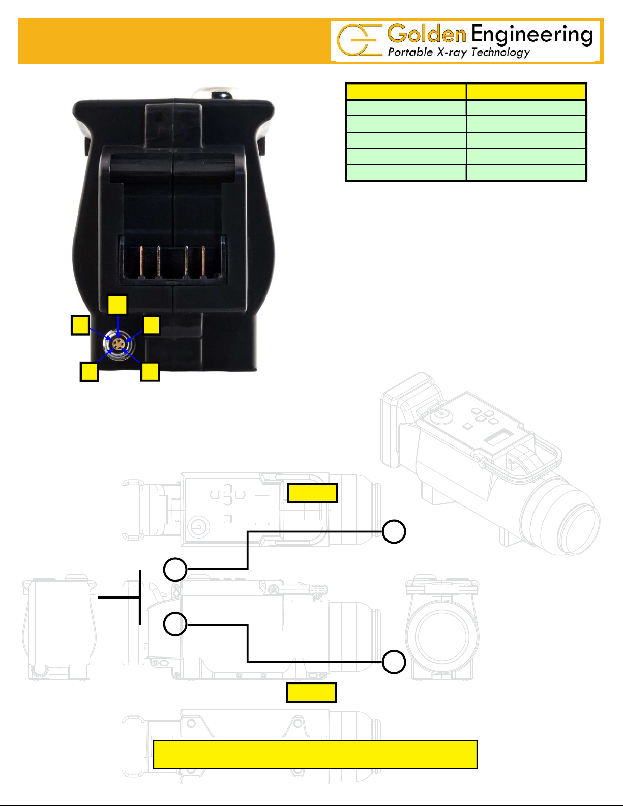
XR150 REAR VIEW/CABLE CONNECTOR
1
52
PIN # DESCRIPTION
1 +5 VOLTS 100 ma MAXIMUM
2 REMOTE SWITCH
3 REMOTE SWITCH - NO DELAY
4 X-RAY ON SIGNAL
5 COMMON 0 VOLTS
3 4
REMOTE CONNECTOR: LEMO EPG.0B.305.HLN
MATING CABLE PLUG: LEMO FGG.0B.305.CLAD 56Z
PIN 2
Remote switch inputs are activated when grounded.
5
PIN 5
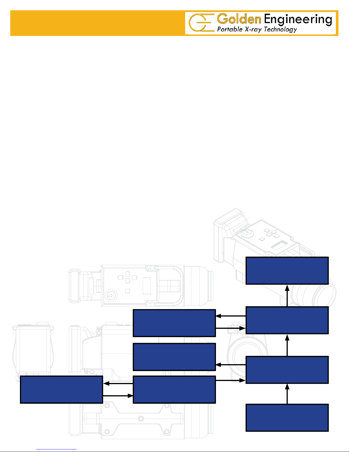
4.0 DESCRIPTION OF OPERATION
The block diagram below illustrates how the XR150 functions. The following sequence of events
takes place each time the XR150 is fi red:
1. User initiates operation of the machine.
2. The control section sends a signal to the converter section to begin oscillating.
3. Once oscillating, the converter section changes the 12 volts DC to 22Khz AC.
4. The transformer charges the High Voltage Capacitor to about 8000 volts.
5. The spark gap arcs after the High Voltage Capacitor reaches proper voltage.
6. The pulse detector signals the control block that the unit has pulsed.
7. As the High Voltage Switch is closed, a high voltage transient of approximately 150,000 volts
and 30 nanoseconds in duration is applied across the x-ray tube generating x-rays.
The closing of the High Voltage Switch produces an audible pulsing sound. The XR150 cannot
produce x-rays without the pulsing sound so it serves as an additional warning the XR150 is
functioning.
This unit generates x-rays through high voltage bombardment of a tungsten target. The XR150 does
not contain radioactive materials. All the high voltage is contained within the aluminum canister
and as long as the canister is not punctured the operator is not exposed to dangerous voltages.
USER INTERFACE
BLOCK DIAGRAM
SPARK GAP
PULSE DETECTOR
CONTROLLER
X-RAY TUBE
HIGH VOLTAGE
CAPACITOR
CONVERTER
BATTERY
6
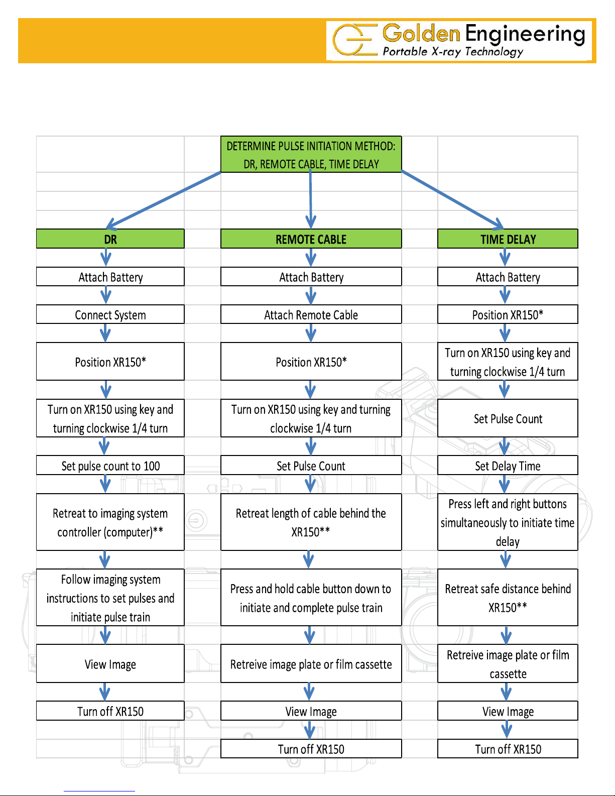
5.0 OPERATING INSTRUCTIONS
The following are basic operation instructions to take an X-ray image using the XR150. Certain applications may
require modi cations to these basic procedures.
7
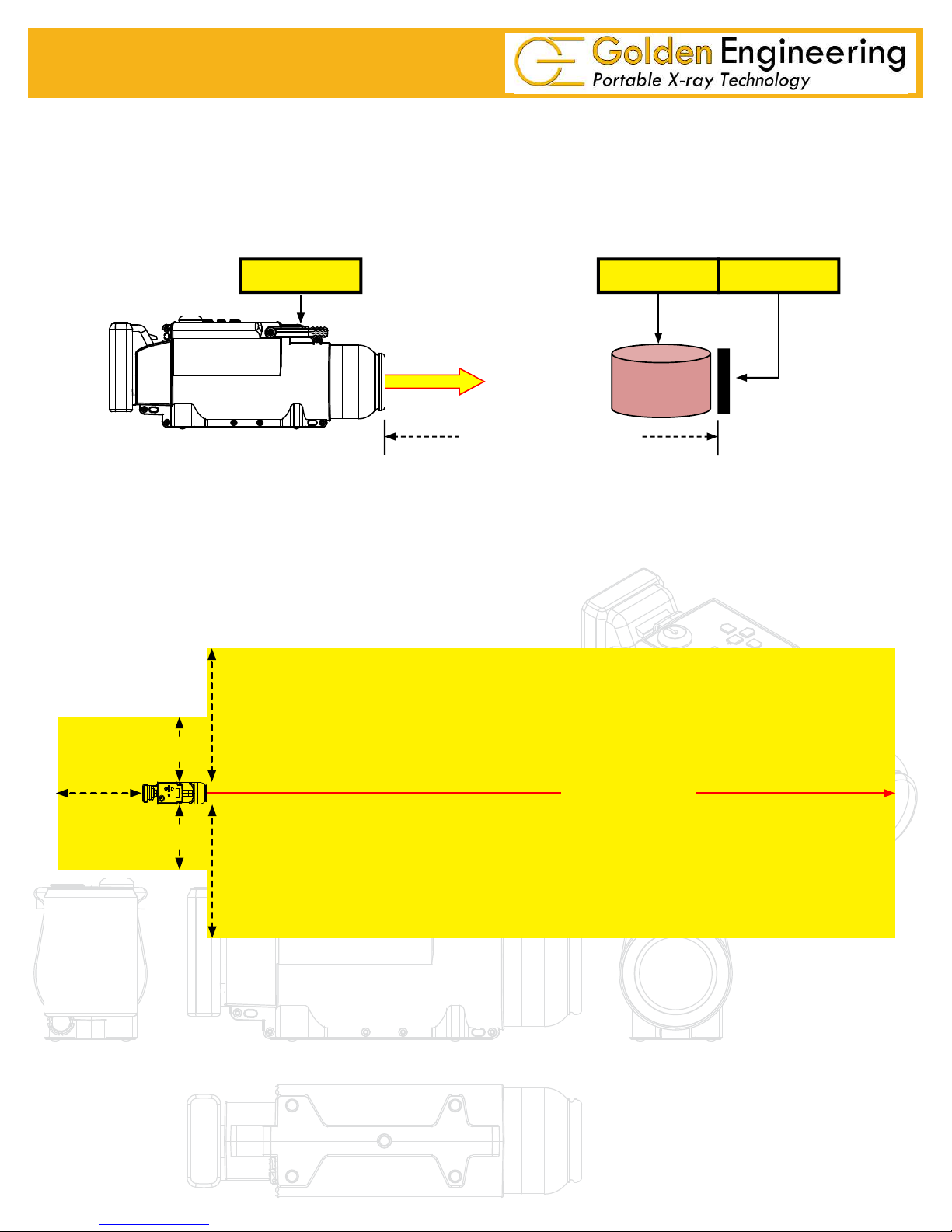
*XR150 should be positioned directly in front of the object to be X-rayed and the imager placed directly behind
the object to be X-rayed. Imager should be placed as close to the object as possible. Distance between XR150
and imager is usually 24 to 72 inches (30 to 180 cm). During operation XR150 should be stabilized on a at
surface, a tripod, or a custom xture suitable for holding the 5 pound (2.2 Kg) XR150.
XR150 OBJECT IMAGER
24 to 72 inches (30 to 180 cm)
**OPERATING PRECAUTIONS: The operator should always stand at least 10 feet (3m) behind the X-ray
unit and clear all personnel at least 10 feet (3m) behind the unit or at least 100 feet (30m) from the front of the unit
before pulsing. The exclusion zone (below) should be a controlled area free of all personnel while
X-ray pulses.
10’(3m)
20’ (6m)
10’(3m)
100’ (30m)
X-ray Beam
10’(3m)
20’ (6m)
Figure 4: Exclusion Zone
8
 Loading...