

Golden Eagle Cam Gear User Manual
Golden Eagle Mfg.
Cam Gear Install
Thank you for your purchase of Golden Eagle Mfg. products for your high
performance needs. You now own one of the best products on the market, all 100%
made in the USA! We are very confident you will be more than pleased with your
purchase. If you ever experience any problems, have any concerns or just want to
give some advice, we would love to hear from you.
(909) 592 – 4311 or e-mail
Cam Gear Bolts Are NOT Tight!!!!!
! WARNING !
gear install. Do not attempt to perform this installation procedure if you are not
very familiar with how the timing belt system works. Incorrect disassembly or reassembly of the timing belt system could lead to extensive engine damage! Always
have a shop manual on hand for reference when performing the cam gear install.
Items this box should contain:
• 12 point 5/16” socket for the cam gear bolts
• 10 – 12 – 14 – 17 – 19 mm socket set w/ ratchet and extension
• 10 – 12 – 14 mm open end wrenches
• Flat head screw driver
Some of our cam gears come with a key and some do not. If you need to find out
which gears require a key, if not supplied, please give us a call at (909) 592 – 4311
or e-mail at sales@goldeneaglemfg.com
1. First, take off the spark plug wire cover, the spark plug wires and the valve
cover. Before you remove the valve cover, be sure to gather up all the nuts
and washers to prevent them from falling into the engine. Carefully remove
the valve cover and set in a clean place up-side down.
2. You will need to remove all of the spark plugs so that the engine can be
rotated easily by hand.
Once the valve cover is removed, the upper timing belt cover can be removed.
3.
4. Next, use a 19 mm (sometimes a 17mm) socket and ratchet to rotate the
engine so that the number one cylinder is at Top Dead Center (TDC) in the
intake stroke. Simply turn the crank counter clockwise until the whit mark on
the crank pulley lines up with the timing mark on the lower timing belt cover.
5. Mark the timing belt at TDC. Take the stock gears off using a 14 mm socket
and an impact wrench. Loosen the belt tensioner (14 mm) and slip the belt
off of the stock gears. Carefully remove the stock gears taking caution not to
lose the key (s).
6. Install the new cam gears along with the keys and replace the cam shaft bolts
using a 14 mm socket and a torque wrench to 27 ft-lbs. (38 N-m) Be sure to
tighten the 12 point bolts that fix the cam gear timing, as they do not come
tightened from the factory. To tighten the belt, rotate the engine over twice
counter clockwise then tighten the belt tensioner bolt 14 mm to 33 ft-lbs (45
N-m) Make sure that when the crank is at TDC, the cam gears line up with
the inscribed alignment marks (dotted lines on the gear outers ) Tighten the
cam gear bolts to a torque of 18 ft-lbs to prevent the gears from slipping
during vehicle operation ( recheck the bolts periodically. Use Loctite
whenever possible)
Replace the valve cover and spark plug wires accordingly.
7.
Rotate the motor by hand using a wrench on the crank pulley bolt, rotating it
8.
counter clockwise at least two full rotations to be sure there are no
interference issues with the valves and pistons.
Once everything check out, start the motor and check for leaks and make sure
9.
everything is in order. Remember, we always suggest having a shop manual
on hand for reference on removal and replacement of the cam gears.
Optional: cut the valve cover and belt cover to allow easy access to make gear
adjustments.
Again, we thank you for your purchase and we are always here for your input.
Golden Eagle Mfg.
414 Borrego Ct.
San Dimas, CA 91773
Ph. (909) 592 – 4311
Web www.GoldenEagleMfg.com
Sales@goldeneaglemfg.com
Be sure to tighten the bolts before engine start-up.
We strongly suggest having a trained technician perform the cam
sales@goldeneaglemfg.com
®
Golden Eagle Mfg.
Reading the Amplified Scale
Timing Marks on ADJUSTRU Cam Gear
This is one of the easiest ways to line up the correct degree on any cam gear. It is as
easy as 1 – 2 – 3. No more squinting and trying to get the lines that you “think” are
the correct degrees to line up.
The following will help you get your bearings on how to use this scale.
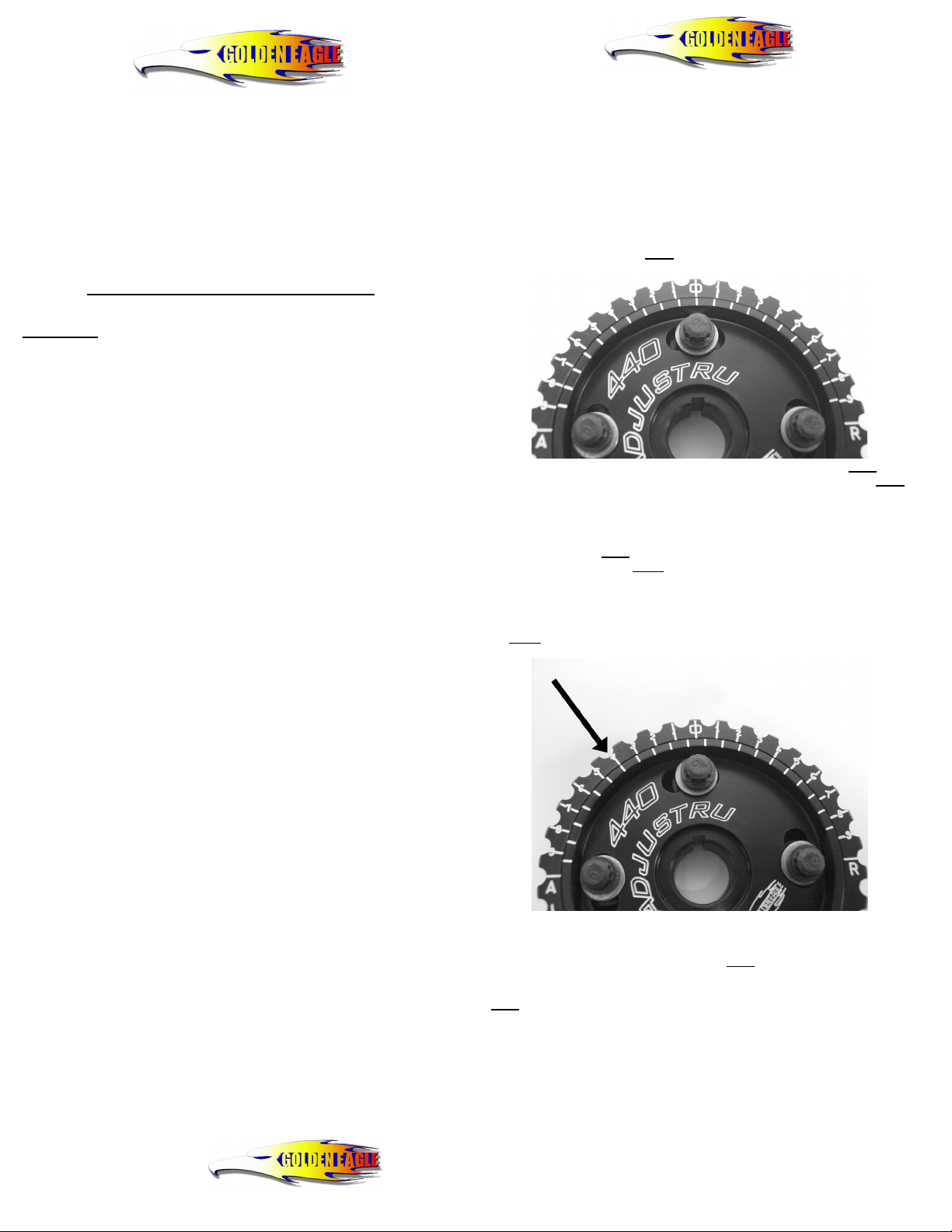
First, you need to set the gear at 0° ( degrees ) by lining up the “ 0 ” line on the
outer with the “ 0 ” line on the inner
the slots. ( see photo below )
Notice how the “ 0 “ line on the outer lines up with the “ 0 “ line on the inner and
the bolts are centered in the slots. Also note that the further most lines on the inner
are both under the 9° mark in both the Advanced and Retard section. This helps in
finding true 0°.
Next, the “ A “ and the “ R “ indicate the Advanced and Retard section of the cam
gear. If you rotate the inner
section and if you rotate the inner
the advanced section. There is also an arrow that shows the rotation of the gear
while the motor is running.
Lets say you want to set the gear at 4° Advanced. All you will need to do is rotate
the inner
mark on the outer. ( see photo below )
This rule applies to any degree adjustment you will need to make when using these
cam gears.
Rule of thumb, 0° is always when a line on the inner
the outer and the bolts are centered in the slots. When adjusting to a certain degree,
focus your eye on the degree you desire, either in Advance or Retard, and rotate the
inner
to the left ( counter-clockwise ) until a line matches up with the “ 4° “
until a line matches up with your desired outer degree mark.
Always remember to tighten up the cam gear bolts
after you get them set to your desired degrees!
If you have any question regarding this Amplified Scale, please give us a call at
(909) 592 – 4311 or e-mail us at sales@goldeneaglemfg.com.
. This is easily done by centering the bolts in
to the right ( clockwise ) you will be in the Retard
to the left ( counter-clockwise ) you will be in
lines up with the “ 0 “ line on
 Loading...