

Goldacres ZETA 140, ZETA 70, ZETA 200, ZETA 230, ZETA 170 Operator And Parts Manual
...
1
UDOR Diaphragm
Pumps
Operator’s & Parts Manual
GA8700374 REV 1.0 MAR 16

2
General Information and Specs ..........3
Pump Identication ....................3
Before Start Up .......................4
Controls on System ....................5
Installation, Start Up and Switching O ....6
Maintenance .........................7
Lubrication ...........................8
Trouble Shooting ......................9
Oil and Weight .......................10
Torque Specication ..................11
Pump ...............................14
Pump Diaphragms ....................14
To replace a side diaphragm in pump: ...15
Air Damper Chamber .................15
IOTA 20 .............................16
Kappa 40 / Delta 40 ...................18
Zeta 70 .............................20
Zeta 85 .............................22
Zeta 100 ............................24
Zeta 140 ............................26
Zeta 170 ............................28
Zeta 260 ............................30
Zeta 300 ............................32
Pump Kits ...........................33
Zeta pump kit contents ................34
Safety ..............................35
The Operator ........................35
Safety Precautions ...................35
Personal Protective Equipment (PPE) ....36
Warranty ............................36
Goldacres Warranty Statement .........37
Terms and Conditions .................38
Revision number: 1.0
2-3-2016
Operator’s Manual Part Number: GA8700374
Contact
Goldacres
1-3 Morang Crescent,
Mitchell Park Vic 3355
P: 03 5342 6399
F: 03 5342 6308
info@goldacres.com.au
Please note: All information in this operator’s manual is based on the latest product information available at the time of printing.
The policy of Goldacres is one of continuous improvement and as such, Goldacres reserve the right to alter any specications and
designs without notice and without incurring any obligation regarding such changes. No part of this manual may be reproduced
without written permission from Goldacres. All photographs and technical information remain the property of Goldacres.
3
General Information and
Specs
General
Diaphragm pumps are constant displacement
pumps providing a consistent ow, largely
unaected by changes to operating pressure.
Diaphragm pumps have good suction capacity
and can easily self prime, they can also run
dry without damage. On Goldacres sprayers
we supply the operator with the pump RPM
and therefore the operator can be condent
of the ow rate of the pump and condent
the agitation to sprayer tank is consistent,
even when quite large changes to operating
pressures are made.
Centrifugal pumps - It is not possible to
be certain of the pump ow by monitoring
pump speed and the limited suction capacity
of a centrifugal pump adds a further area of
uncertainty to pump output. Centrifugal pumps
ow rate varies considerably with pressure
changes.
Maintenance - It is sometimes claimed
centrifugal sprayer pumps require less
maintenance than diaphragm pumps. At
Goldacres we have not found this to be the
case. Cast iron pumps are subject to chemical
erosion. Centrifugal pumps which are run
dry even for short periods can be severely
damaged.
Flow Vs Pressure.
The ow output by diaphragm pumps are
largely unaected by changes to operating
pressure.
For example:
UDOR 250 l/min pump @ 500rpm
0 Bar = 225.7 l/min output
10 Bar = 223.1 l/min output
Maximum achievable ow to the
boom.
Goldacres design sprayers so that the ow to
the boom should be approximately half the
stated maximum ow of the pump - this is due
to the pump also needing to supply agitation
to the main tank. For example a 250 l/min
pump should realistically achieve a maximum
ow of approximately 125 l/min to the boom.
Goldacres Crop Cruisers are tted with
hydraulic drive diaphragm pumps.
Trailed Sprayers - Hydraulically driven pumps
are becoming more common as tractors
come out with more hydraulic outlets. Fitting
a hydraulic drive to the pump eliminates any
maintenance or safety issues that are often
associated with PTO shaft drives.
The UDOR diaphragm pumps tted to
Goldacres sprayers do not require a coupling
between the hydraulic motor and pump. The
MI pump is tted with a ange which will
accept this motor shaft. A hydraulic drive is
required for tractors tted with 1000 RPM PTO
drives. Standard diaphragm pump RPM is 540.
To measure pump RPM with a hydraulic drive
tted an RPM sensor is tted on the shaft
of the pump which will provide you with a
readout that will be shown on your controller.
There are many factors that can change how
often a pump needs to be serviced - however
it is common for pumps to be serviced
annually as preventative maintenance which
will ensure reliability when the sprayer is in
operation.
A quality multigrade engine oil should be used
in the pump.
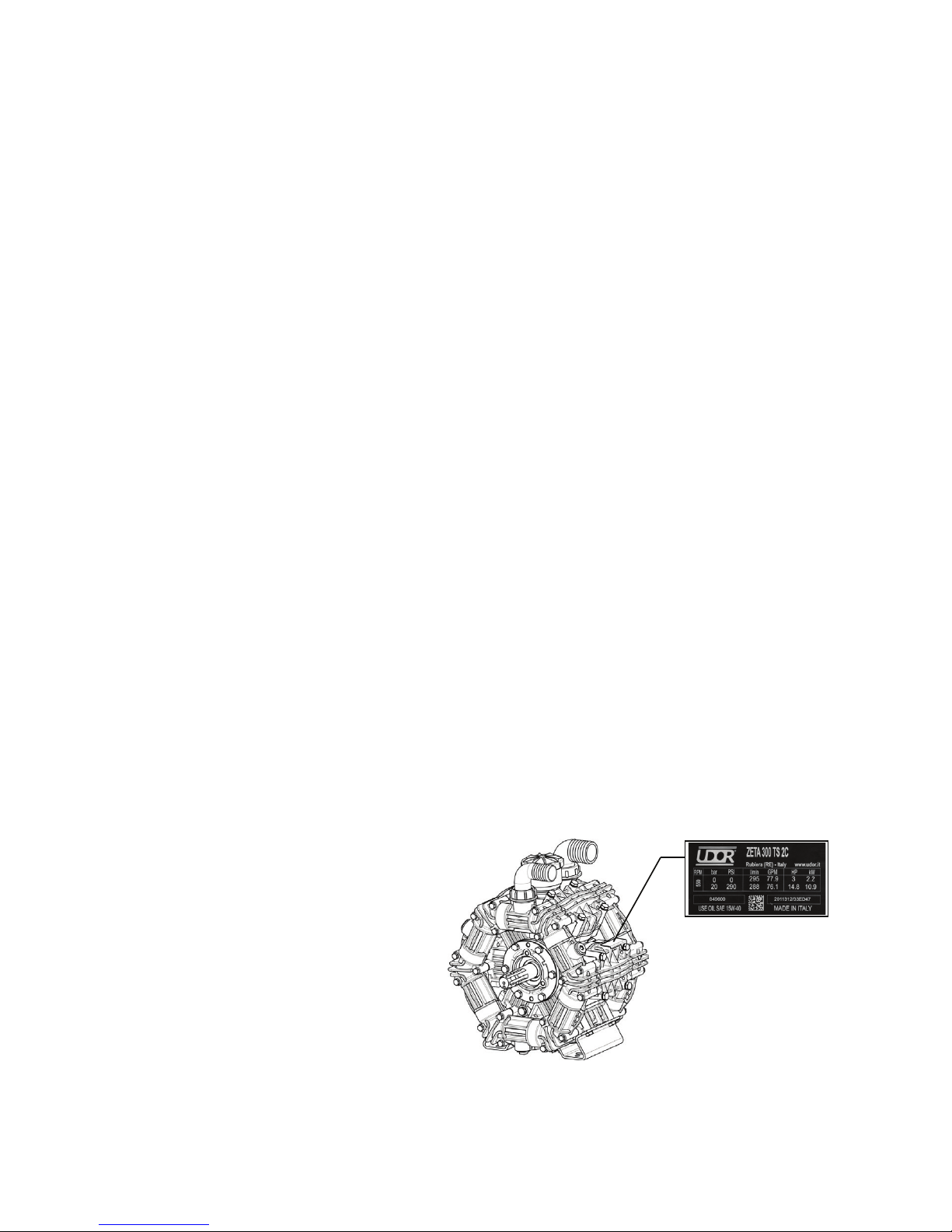
Pump Identication
The label on the pump bears the model, the
code, the serial number and the main technical
specications with the maximum operational
values of the product. The specimen at the
side is an example of a label and its position
on the Pump.
IC - 1⅜” 6 Spline PTO
TS2C - Through Shaft,
1⅜” 6 Spline PTO
both sides
MI - 25.4mm Internal
hole for a Hydraulic
motor.
VA - Mounting surface
for gear box drive,
(engine Drive).
4
Safety Symbols
The “WARNING” symbol here at the side
draws the operator’s attention to situations
and/or problems related to the correct
operation of the Pump.
The “DANGER” symbol here at the side
draws the operator’s attention to situations
and/or problems that could compromise
the safety of people.
Introduction
The Diaphragm Pumps of UDOR, with radial
piston kinematic drive, are designed and
manufactured to pump or transfer water or
pesticides and herbicides in water solution
to be used according to the instructions of the
actual producers.
They are generally driven by: electric motors,
endothermic petrol or diesel engines and
hydraulic motors, tractor P.T.O.. Couplings
may be fullled by means of transmission
shaft, direct anging, reduction unit or
multiplier, joints, pulleys and belts.
The Pump is supplied to be installed on
a more complex machine or plant; the
manufacturer of such machine or plant
shall add all the information related to
safety of the assembled machine/plant
fullled.
Intended Use
The Diaphragm Pumps of UDOR are designed
for use in machines or systems that transfer
water or pesticides or herbicides, under
pressure, such as the following for example:
Sprayers, Mist Sprayers, Herbicide Spray
Booms, Gardening, Civil and Industrial
Washing Systems, Drain and Pipe Cleaning,
Fire-ghting, Antifreeze Systems.
The temperature of the workplace shall be
between: Min. 0°C (32°F) - Max.45°C (113°F)
The Pump cannot be used submerged under
any type of liquid.
Operational Restriction
The specications of the liquid to be used
are described in detail herewith: do not use
for dierent liquids; in particular, it is NOT
possible to use UDOR Pumps in the following
conditions:
- In the presence of water with high salt
content, such as seawater for example.
- In workplaces where there is a corrosive
or explosive atmosphere.
- In the presence of any liquid that is
not compatible with the constructional
material of the Pump.
- To pump paint, solvents, fuel and any
ammable liquid (not suitable for ATEX
workplaces).
- For foodstus.
- To wash people, animals, live electrical or
electronic equipment.
- To wash the Pump itself.
General Warnings
- Never start the Pump under pressure.
- Constantly check the state of wear of
the pipes and relevant ttings, especially
those under pressure. Pipes with signs of
abrasion or that do not guarantee a perfect
seal shall be replaced.
- Protect rotating parts with a cover to
prevent contact.
- The Pump is designed to be integrated in
a machine or system, with various supply
systems, which may make the noise
level vary, even quite substantially. The
manufacturer of such machine or system
shall assess the level of noise emitted
by the assembled machine or system
and inform the user appropriately, also
in relation to the use of suitable personal
protection equipment.
Before Start Up
Liquids To Be Pumped
The Pump is designed and manufactured to
transfer water or pesticides and herbicides
in water solution to be used according to the
instructions of the actual producers.
The liquid intake must be free from sand or
other solid particles in suspension.
The liquid intake shall have viscosity and
density similar to water.
The temperature of the liquid to be pumped
must be between 5°C (41°F) and 38°C (100°F).
Any other use is not admitted unless
authorised in writing by the Engineering
!
!
!
!
!
!
5
Department of UDOR.
Inlet And Outlet Of The Pump
The Inlet of the liquid to be pumped, also
called intake or supply, is generally of larger
diameter than the Outlet, also called delivery.
The Inlet and Outlet CANNOT be inverted.
Inlet Conditions (Suction)
Make sure the supply line is connected
correctly and that it complies with the
following requisites:
- Any point of the inlet pipeline cannot be
smaller than the diameter of the Pump
inlet.
- Be absolutely leak-proof to avoid any air
inltration.
- Not have 90° bends near the Pump inlet.
- Not have contractions or restrictions.
- Avoid any turbulence near the Pump inlet
and in the supply tank.
- If an inlet lter is used, it must allow 200%
more ow than the ow required by the
Pump. It must not cause any contraction
or any pressure drop. The lter should
grant a ltration degree between 32 and 50
Mesh and should be cleaned on a regular
basis to ensure its proper functionality.
- Maximum inlet pressure admitted: 0.5 bar
(7 PSI).
- Maximum negative inlet pressure
admitted:-0.2 bar (-3 PSI) [-6 inch.Hg].
- Maximum oset admitted between pump
and supply source underneath: 2m. (6.5ft.).
Outlet Conditions
Make sure the delivery line and all the
accessories are connected correctly, secured
rmly, hermetically sealed and that the pipes
are sized appropriately. All pressurised pipes
must be marked durably with the maximum
admitted pressure, which must never be less
than the maximum working pressure of the
Pump, written on the Label.
Speed and Rotation Direction
The rotation speed of the shaft of the
Pump must never exceed the RPM written
on the Label of the actual Pump.
The minimum RPM admitted is: maximum
RPM x 0.6.
The rotation direction of the shaft of UDOR
Pumps may be clockwise or anticlockwise.
Controls on System
Unloader Valve
A pressure regulator valve must be installed to
avoid the pressure exceeding the maximum
limit indicated on the Label of the Pump.
Use of the Pump, even for a short period,
with a pressure higher than such limit
would damage the Pump itself.
The regulator valve shall be compatible
with the maximum pressure, ow rate and
temperature values written on the Label and in
the “INLET CONDITIONS”.
Incorrect installation of the pressure
regulator valve could cause serious
personal injuries and damage to property
as well as seriously damaging the actual
Pump.
The circuit must be equipped with another
safety valve to prevent the maximum pressure
from being exceeded in the case of anomalies
in the pressure regulator valve.
Nozzle
A deteriorated nozzle could cause a drop
in pressure; in this case, do not adjust the
pressure regulator valve in the attempt to
increase the pressure of the system because
when the delivery line closes, this would cause
a boost in pressure, which could damage the
Pump.
If the pressure drops, it is advisable to replace
the nozzle and adjust the system’s pressure
again.
The ow rate of the Pump must be at least
10% higher than the ow rate that the utilities
demand; the excess ow rate must be
discharged.
Pulsation Dampener (Accumulator)
Before starting the Pump, verify the air
pressure in the accumulator, if present.
This operation may be carried out, with the
Pump o, connecting an air source to the
ination valve.
The air pressure should be checked
periodically.
Using the Pump without air in the
!
!
!
!
!

6
accumulator may cause system
malfunctioning, damage the accumulator
diaphragm or the whole Pump.
The accumulator’s air pressure varies
according to the Pump’s operating pressure:
Pump
Working
Pressure
bar
2 5 10 20 30 40 50
PSI
29 72 145 290 435 580 725
Accumulator
bar 1 2 4 5 6 7 8
PSI 15 29 58 72 87 102 116
UDOR normally inates the Pumps pulsation
dampener at a pressure of 5 bar (72 PSI)
approx.
Pressure Gauge
Install a gauge as near as possible to the
outlet of the Pump because the maximum
pressure written on the Pump’s Label refers to
the pressure detected in that point and not on
the nozzle or on other accessories.
All the components of the machine
or of the circuit must have technical
specications compatible with the data
written on the Pump’s Label.
Installation, Start Up
and Switching O
Positioning
Smaller and lighter pumps can be handled by
hand in compliance with current standards.
Heavier pumps must be handled using a
suitable lifting device. If you need to use a
lifting device, use appropriate strap/s, being
careful not to damage the product. The weight
of the pumps is written in the table on page
10.
To safeguard the lifetime of the components
subject to wear and tear such as valves and
diaphragms, the pump should be installed
below or at water level.
UDOR Diaphragm Pumps are, in any case,
self-priming; they may be installed above
the water source. In this case, the maximum
allowed dierence in height is 2 mt. (6.5 ft.).
If the Pump is used in a particularly dirty
workplaces or is exposed to atmospheric
agents, you are recommended to protect it,
respecting the ventilation conditions.
Assembly
Fit the Pump on a rigid surface keeping the
power take-o and support feet horizontal to
ensure correct drainage in the case of leakage
of water or oil. The Pump must be secured
rmly on a base, which must be perfectly
aligned with the transmission components. In
the case of belt transmission, make sure the
pulleys are aligned and check the tension of
the belts.
Use appropriately sized hoses, both on the
inlet and outlet of the Pump, according to the
technical specications written on the Label.
Start Up
Before starting, check the following:
- Check the oil level through the dedicated
oil reservoir or inspection cap; top-up if
necessary.
- Check the pressure value on the
accumulator, if installed; inate or deate if
necessary.
- The pressure regulator valve must be set
at “0” pressure to favour intake.
Start and run the Pump for approximately 10
seconds until all the liquid has discharged
from the delivery line. Once the intake cycle
is complete, you can set the Pump at the
required pressure, by adjusting the pressure
regulator valve, without ever exceeding the
maximum pressure written on the Pump’s
Label.
Switching O and Storage
After use or if the Pump is to be put away in
storage, wash it internally. You can do this by
running the Pump for several minutes with
clean water, then disconnect the supply line
and leave the Pump to run for approximately
15 seconds so that all the water inside the
pump is drained.
A few minutes devoted to the internal washing
of the pump brings considerable benets in
terms of the pump’s lifetime.
Never leave liquid inside the pump.
Damage to the diaphragms or to other
components is often caused by liquid that
is left inside the pump for a long time.
Do not wash the Pump externally: water
could get into the Pump crankcase, for
!
!
!
7
!
example through the seal rings of the
crankshaft.
Do not throw the liquid used to wash
the Pump outdoors but observe current
standards.
Precautions Against Freezing
If shutdown during winter or in the case of
places and seasons subject to frost, once the
Pump has nished working, run it for the time
required to Pump an emulsion of 50% of clean
water and 50% of antifreeze uid through it in
order to prevent freezing and damage to the
Pump.
The Pump must not be used to Pump
antifreeze uid that is not mixed with
water. In the presence of ice or very
cold temperatures at the workplace, the
Pump must never be started, otherwise
the Pump could be seriously damaged. To
start the system, the whole circuit must be
completely defrosted.
Maintenance
Routine Maintenance
If the Pump is used for light-duty purposes,
the following routine maintenance jobs are
advised:
- After the rst 50 hours: Oil change (see
section 9.2 - Lubrication)
- Every 500 hours: Oil change - Replace the
diaphragms (see instructions below)
- Every 1000 hours: Replace the valves
For heavy-duty purposes, carry out the
maintenance jobs more often.
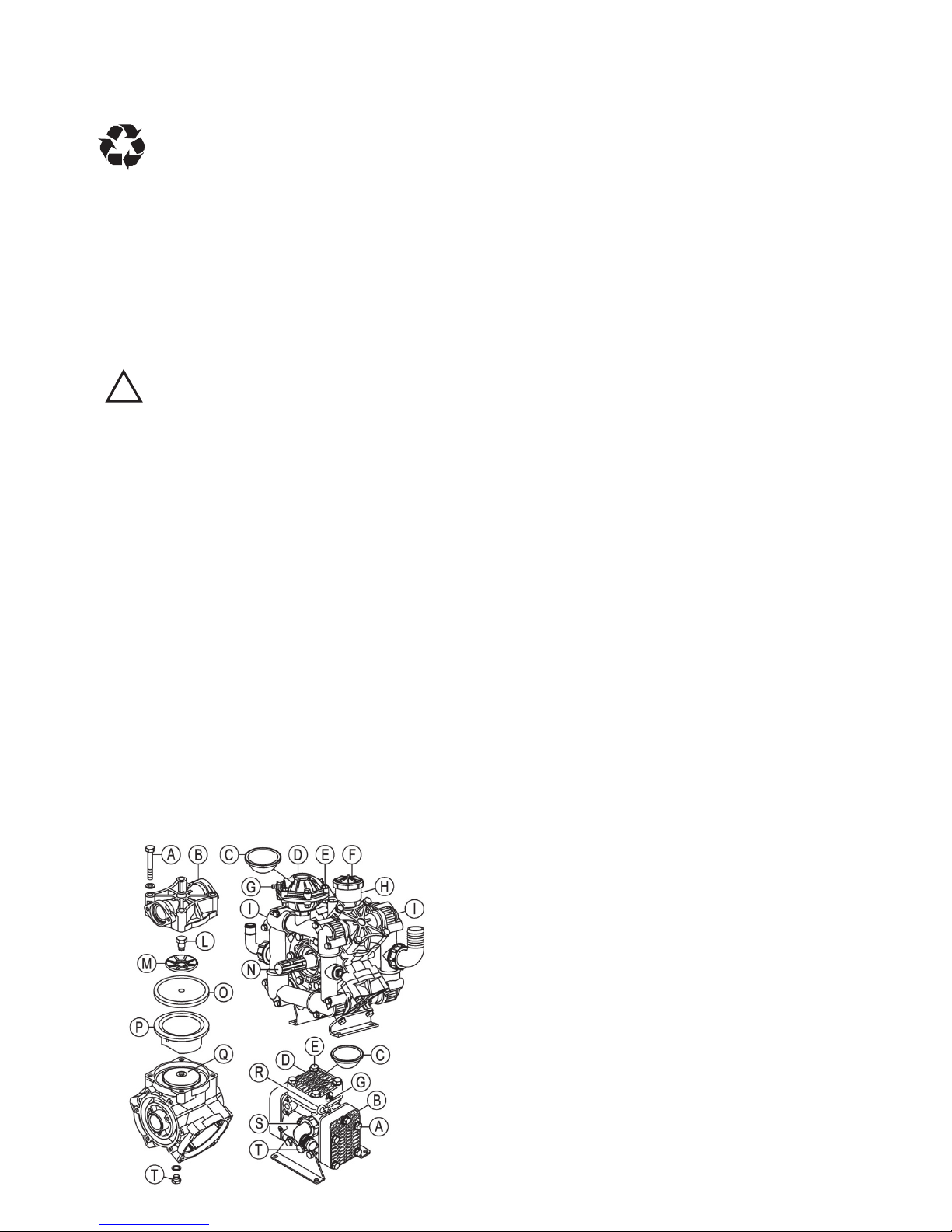
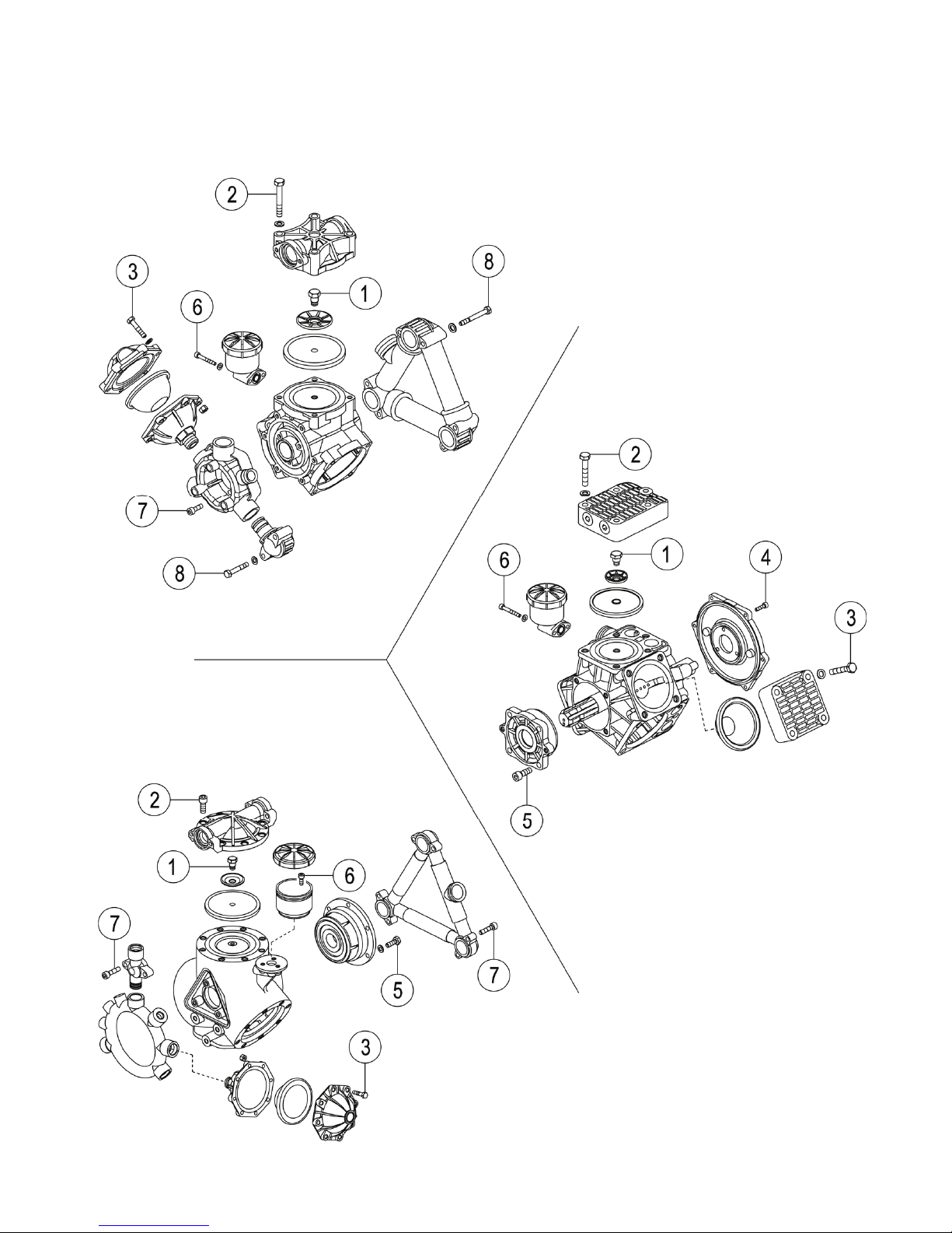
1. DRAIN CRANKCASE OIL: Drain Pump
crankcase by removing the oil drain plug
(T) located at the bottom of the Pump, also
remove the oil ll cap (F) or plug (R).
2. EXTERNAL MANIFOLD REMOVAL: If your
Pump has external manifolds ( I ), these must
be removed prior to heads (B) removal.
3. HEAD REMOVAL: Do repairs one head (B)
at a time. Remove the head bolts (A), then
remove the Pump head (B) which may require
some “light” prying.
4. DIAPHRAGM REMOVAL: Turn crankshaft
(N) to bring piston (Q) up to the top of its
stroke, remove the diaphragm bolt (L) and
washer (M), then remove the diaphragm (O).
If necessary, take o one sleeve (P) and wash
well the internal components using diesel
fuel. The sleeve (P) must be re-mounted in the
same position as before.
5. INSTALLING NEW DIAPHRAGMS: Clean
well the threaded hole of the piston (Q). Install
the diaphragm bolt (L) and washer (M) into the
new diaphragm (O). Install this assembly to
the piston (Q). Use Loctite 243 thread locker
or equivalent on the diaphragm bolt (L). Then
torque to the recommended specications
(see page 12). Now rotate crankshaft (N) to
bring the piston (Q) and diaphragm (O) to the
bottom of its stroke. Then seat the outside
edge of the diaphragm (O) into the Pump
body.
6. HEAD INSTALL: When reinstalling the Pump
head (B) it is very important to make sure that
the check valves are installed correctly. For
each cylinder there are two valves, one valve
lets the uid ow into the head, the other
valve lets the uid ow out of the head. PAY
VERY CLOSE ATTENTION TO THIS. After
having correctly positioned the Pump head (B),
tighten the screws (A) with the proper torque
(see page 12).
7. INSTALLING PULSATION DAMPENER
DIAPHRAGM: Bleed o the air in the chamber
using the air-valve (G) on the dampener,
then remove the cover bolts (E), cover (D)
and diaphragm (C), install correctly the
new diaphragm (C). Reinstall cover (D) and
tighten the screws (A) with the proper torque
(see page 12). Recharge dampener with air
according to UDOR specications at page 6.

8
8. REFILL PUMP CRANKCASE: Re-mount
the oil drain plug (T). Fill Pump with SAE
15W-40 OIL to recommended mark on the oil
reservoir (H) or on the sight glass (S). Rotate
the crankshaft (N) while lling to eliminate air
pockets. Re-mount the oil ll cap (F) or the oil
ll plug (R).
9. INITIAL START UP: Start the Pump with
the outlet line at “0” pressure; after about 5
minutes at “0” pressure you may increase
the outlet pressure and make a few cycles
of pressure on/o. This will evacuate any
remaining air pockets in the crankcase. Turn
Pump o and re-check oil level. Rell as
necessary to proper oil level.
IMPORTANT: During initial start up, monitor
the oil color. If it turns milky white, the
diaphragms were not seated correctly.
Lubrication
The Pump is supplied with the correct amount
of lubrication oil (see table on page 10).
Periodically check the oil level in the Pump
through the oil level indicator.
Use OIL type SAE 15W-40 or equivalent. Here
are some recommended types of oil:
Brand Type
AGIP F.1 Supermotoroil 15W-40
BP Vanellus C 15W-40
CASTROL GTX 15W-40
ESSO Unio 15W-40
MOBIL Super M 15W-40
SHELL Rimula R4 15W-40 / Helix
Super 15W40
TOTAL Rubia 15W-40 / Quartz 5000
15W-40
The oil is to be changed by draining it through
the dedicated bottom discharge cap and
strictly with the Pump stopped.
The oil level could vary during priming ; then it
will stabilize when the system is pressurized.
If the oil level gets lower during the rst few
hours of the pump’s operation , it could be
normal. Simply rell. If instead , the oil level
changes considerably after several hours of
operation, the pump’s diaphragms might be
damaged or there might be restrictions along
the suction line.
Do Not Start The Pump If There Is No
Oil In The Pump!
During maintenance, you are
recommended to:
- Use and wear suitable personal
protection equipment (i.e. gloves).
- Wait for the machine to cool down and to
have stopped completely.
During maintenance, do not throw
residues outdoors but observe current
standards.
If the Pump is to be scrapped:
1. Separate the various parts depending on
their type (i.e. plastic, harmful uids, metal
etc.).
2. Use public or private waste disposal
systems envisaged by local law to dispose
of waste.
3 This device could contain harmful
substances: improper use or incorrect
disposal could have negative eects on
human health and on the environment.
!

9
Problems Probable Causes Solutions
No pressure.
Very little pressure.
Pressure drops below
working range when relief
valve is open to boom or
gun.
Insucient strainer capacity,
or dirty or plugged strainer.
Use larger capacity strainer or
clean strainer.
Suction hose restriction. Eliminate restriction.
Collapsed suction hose inside
or outside tank restricting
ow.
Replace collapsed hose.
Air leak in inlet line. Examine hoses and ttings, ensure
air tight t and no leaks.
Pressure relief valve stuck or
worn.
Repair or replace relief valve (§).
Excessive tank foam due to
low tank volume.
Rell tank.
Nozzle volume is greater than
Pump capacity.
a. Check relief valve adjustment.
b. Reduce nozzle orice size or
number of nozzles used.
One or more check valves
seating improperly.
Clean or replace check valves(§).
Excessive gauge vibration.
Excessive pulsation.
Pulsation dampener pressure
too low or too high.
Adjust pulsation dampener
pressure. (see page 6) – (§).
Air leak in inlet line. Examine hoses and ttings, ensure
air tight t and no leaks.
Insucient strainer capacity,
or dirty or plugged strainer.
Use larger capacity strainer or
clean strainer.
Air not entirely evacuated
from Pump cavity.
Run Pump with an open discharge
to totally evacuate air.
Pump does not suck
water.
Air leak in inlet line. Examine hoses and ttings, ensure
air tight t and no leaks.
Insucient strainer capacity,
or dirty or plugged strainer.
Use larger capacity strainer or
clean strainer.
One or more check valves
seating improperly.
Clean or replace check valves(§).
Pump oil has milky color.
The Pump oil comes out of
discharge line; the oil level
drops markedly.
Oil plug pops out.
One or more diaphragm
failures.
STOP THE PUMP
IMMEDIATELY!
Replace the diaphragms (§).
Diaphragm replacement
instructions:
see pages 7-8.
(§)These operations must be carried out by qualied personnel.
!
Trouble Shooting

10
Series Recommended Oil Quantity Pump Weight
Kg. Lbs. Lt. Gal. Kg. Lbs.
ZETA 70 0,5. 1.10 0,56 0.15 9 20
ZETA 85 1,02 2.25 1,14 0.30 12 26
ZETA 100 1,02 2.25 1,14 0.30 13 29
ZETA 120
ZETA 140
1,04 2.29 1,16 0.31 18 40
ZETA 170 1,15 2.54 1,28 0.34 24 53
ZETA 200 1,15 2.54 1,28 0.34 26 57
ZETA 230
ZETA 260
2,40 5.29 2,68 0.71 36 79
ZETA 300 2,50 5.51 2,79 0.74 38 84
RO 320
RO 400
4,10 9.04 4,58 1.21 63 139
IOTA 20
IOTA 25
0,18 0.40 0,20 0.05 4 9
KAPPA 15 0,10 0.22 0,11 0.03 2,5 5.5
KAPPA 25
KAPPA 32
0,26 0.57 0,29 0.08 8 18
KAPPA 40 /
DELTA 40
KAPPA 50
0,49 1.08 0,55 0.15 11 24
KAPPA 33
KAPPA 43
KAPPA 53
0,56 1.23 0,63 0.17 11 24
KAPPA 55
KAPPA 65
0,62 1.37 0,69 0.18 13 29
KAPPA 75 1,04 2.29 1,16 0.31 18 40
KAPPA 100 1,02 2.25 1,14 0.30 20 44
KAPPA 125 1,82 4.01 2,03 0.54 28 62
KAPPA 120
KAPPA 150
1,76 3.88 1,97 0.52 42 93
OMEGA 135 1.45 3.20 1.62 0.42 28 62
OMEGA 140 2,14 4.72 2,39 0.63 40 88
OMEGA 170 2,42 5.33 2,70 0.71 45 99
BETA 110 2,14 4.72 2,39 0.63 45 99
BETA 150 2,42 5.33 2,70 0.71 52 115
BETA 200
BETA 240
4,50 9.92 5,03 1.33 75 165
Oil and Weight
11
Torque Specication
PTO for details on
Torque Specication

12
1 2 3 4
Diaphragm Bolt
(use Loctite
®
243)
Head Bolts Pulsation
Dampener Bolts
Inlet Flange Bolts
MOD. N•m lbf•ft N•m lbf•ft N•m lbf•ft N•m lbf•ft
ZETA 70 25 18 25 18 --- --- --- ---
ZETA 85 25 18 40 30 --- --- --- ---
ZETA 100 25 18 40 30 25 18 --- ---
ZETA 120
ZETA 140
30 22 40 30 25 18 --- ---
ZETA 170
ZETA 200
30 22 40 30 25 18 --- ---
ZETA 230
ZETA 260
ZETA 300
30 22 40 30 --- --- --- ---
RO 320
RO 400
30 22 50 37 --- --- --- ---
IOTA 20
IOTA 25
14 10 25 18 25 18 --- ---
KAPPA 15 14 10 14 10 14 10 --- --KAPPA 25
KAPPA 32
25 18 40 30 40 30 --- ---
KAPPA 40 /
DELTA 40
KAPPA 50
25 18 40 30 40 30 --- ---
KAPPA 33
KAPPA 43
KAPPA 53
25 18 40 30 --- --- 10 7
KAPPA 55
KAPPA 65
25 18 40 30 40 30 10 7
KAPPA 75 25 18 40 30 40 30 10 7
KAPPA 100 25 18 40 30 28 20 10 7
KAPPA 125 25 18 40 30 28 20 10 7
KAPPA 120
KAPPA 150
30 22 45 33 28 20 10 7
OMEGA 135 30 22 40 30 --- --- --- ---
OMEGA 140 30 22 50 37 28 20 --- ---
OMEGA 170 30 22 50 37 28 20 --- ---
BETA 110 30 22 50 37 28 20 --- ---
BETA 150 30 22 50 37 28 20 --- ---
BETA 200
BETA 240
30 22 50 37 --- --- --- ---
Torque Specication
 Loading...