

Goldacres Traymount T3, 3PL Pasture, 3PL - 200-450L, 3PL Medium Frame Operator's & Parts Manual

1
Traymount T3
Operator’s & Parts Manual
GA8700839 REV 0.0 AUG 17
300L - GA6500008

2
Contact
Goldacres
1-3 Morang Crescent,
Mitchell Park Vic 3355
P: 03 5342 6399
F: 03 5342 6308
info@goldacres.com.au
Please note: All information in this operator’s manual is based on the latest product information available at the time of printing.
The policy of Goldacres is one of continuous improvement and as such, Goldacres reserve the right to alter any specications and
designs without notice and without incurring any obligation regarding such changes. No part of this manual may be reproduced
without written permission from Goldacres. All photographs and technical information remain the property of Goldacres.
General Information & Specs ............3
Identication .........................3
Dimensions ..........................4
Parts Ordering ........................4
Key features ..........................5
Pre Operation .........................6
Following delivery .....................6
Tasks prior to spraying .................6
Operation ............................7
Filling ...............................7
After spray application .................8
Transporting the sprayer ...............8
Maintenance and Troubleshooting .......8
Manual Controls ......................9
Calibrating your sprayer ................9
Nozzle Calibration .....................9
Filters ..............................10
Suction Filter ........................11
Diaphragm Pumps ....................12
Pump Diaphragms ....................13
IOTA 20 PUMP Gear Box &
Honda GX100 engine ..................14
IOTA 20 .............................15
6:1 Reduction Gear Box ...............16
Honda GX120 ........................17
Troubleshooting ......................18
Diaphragm Pump .....................18
30mt manual hose reel ................19
AA30L GunJet .......................20
Adjustable ConeJet Nozzle ............21
Safety Decals ........................22
T3 Parts Diagram .....................24
Safety ..............................26
The Operator ........................26
Safety Precautions ...................26
Safe use of chemicals .................28
Personal Protective Equipment (PPE) ...28
Warranty ............................28
Goldacres Warranty Statement .........29
Terms & conditions ...................30

3
General Information and
Specs
General
The tray mount sprayer is ideal for small
acreage and hard to get areas. Our Traymount
range feature engine driven diaphragm pumps
with pressure ranges from 290 –580 Psi.
Our tray mount range are durable with a steel
frame and our tanks are industrial grade UV
protected polyethylene. Our range can be
tted with a host of booms and other handy
options to make your spraying tasks easier.
Know Your Sprayer
Getting to know your sprayer prior to operation
is crucial in the safe and ecient operation
of this equipment. Take the time to familiarise
yourself with all the standard and optional
components tted to your sprayer, not only do
you need to know where key components are
located on your machine you need to become
competent in the correct operation of these
components prior to spraying operation.
It is also important to become familiar with
common spraying methods and common
spraying terms prior to using this sprayer for
the rst time
Chassis:
The chassis is an all steel construction, that is
fully welded for superior strength. The chassis
is shot blasted, primed and then protected
by the Goldacres paint process for excellent
chemical resistance and durability.
Paint Colours:
Steel work: G13 Dark Green
Steel work: N61 Black
Tank:
All tanks are constructed from UV resistant
polyethylene. Polyethylene tanks have a very
high chemical resistance.
Due to the rotomoulding process, there can be
a variance in the overall dimensions of the tank
which in turn results in variations to the tank
capacity. For this reason, calibration markings
should be used as a guide only.
Machine limitations:
All Goldacres equipment is subject to
operating limitations, it is the operator’s
responsibiilty to ensure that this equipment
is being operated within these limitations and
appropriately to the operating conditions at
hand.
Custom built equipment:
Where the owner of this sprayer has requested
that custom built equipment or options
be tted to this sprayer it is necessary to
understand that custom fabrication and
engineering is subject to many variables.
Goldacres cannot fully eld test all custom
built options prior to despatch, and owners
of new sprayers tted with custom built
equipment or options need to understand that
the functionality of these items may require
rening in order to operate as desired.
Optional equipment:
A range of optional equipment is available
for tting to Goldacres sprayers. Specic
information regarding optional equipment
tted to your machine can be found in the rear
of this manual.
WARNINGS
See page 26 for more info.
Identication
When ordering parts or requesting service
information for your sprayer it is important to
quote the serial number of your machine, and
the purchase date, in order to receive accurate
information. The location of the serial number
plate on your machine is shown in the picture.
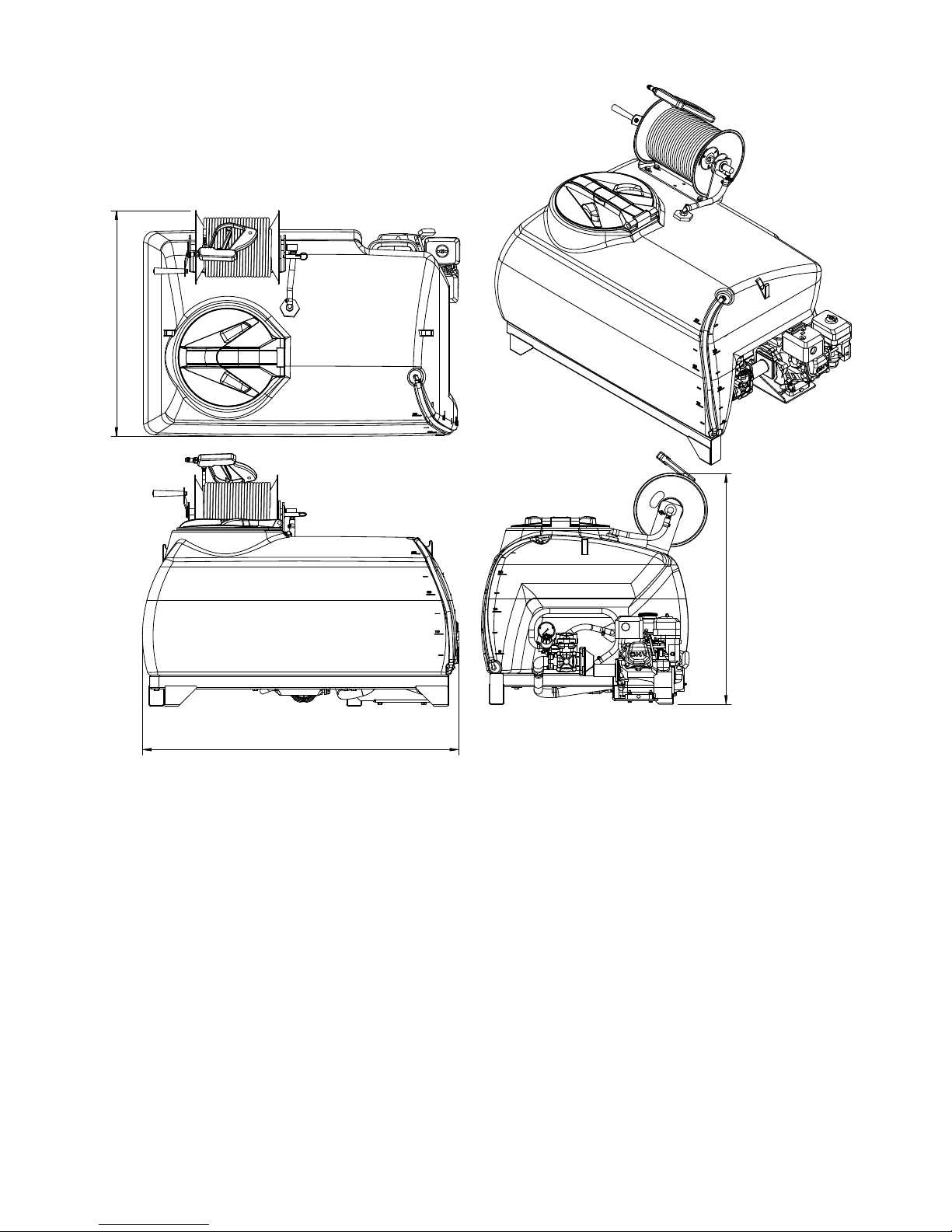
4
Dimensions
1168mm
Traymount T3 300L,
833mm
853mm
Parts Ordering
When ordering parts from your Goldacres
dealer, please quote:
Serial No
Part no required
Part description
Quantity required
When returning parts to Goldacres, or a
Goldacres dealer, for service or repair all parts
MUST be cleaned thoroughly before sending
them. Goldacres cannot expose technicians
to the many potentially hazardous pesticides
and substances that are in use.
NOTE:
Please ensure that all parts are clearly
labelled with the owner’s details, and a brief
description of the fault. Glodacres is not
liable for the return of any goods to Goldacres
or a Goldacres Dealer. The goods must be
returned to the point of sale. The customer
will be responsible for any cost incurred by a
Goldacres appointed person travelling to any
site outside the point of sale.
Genuine Goldacres parts only should be used
on Goldacres equipment.
5
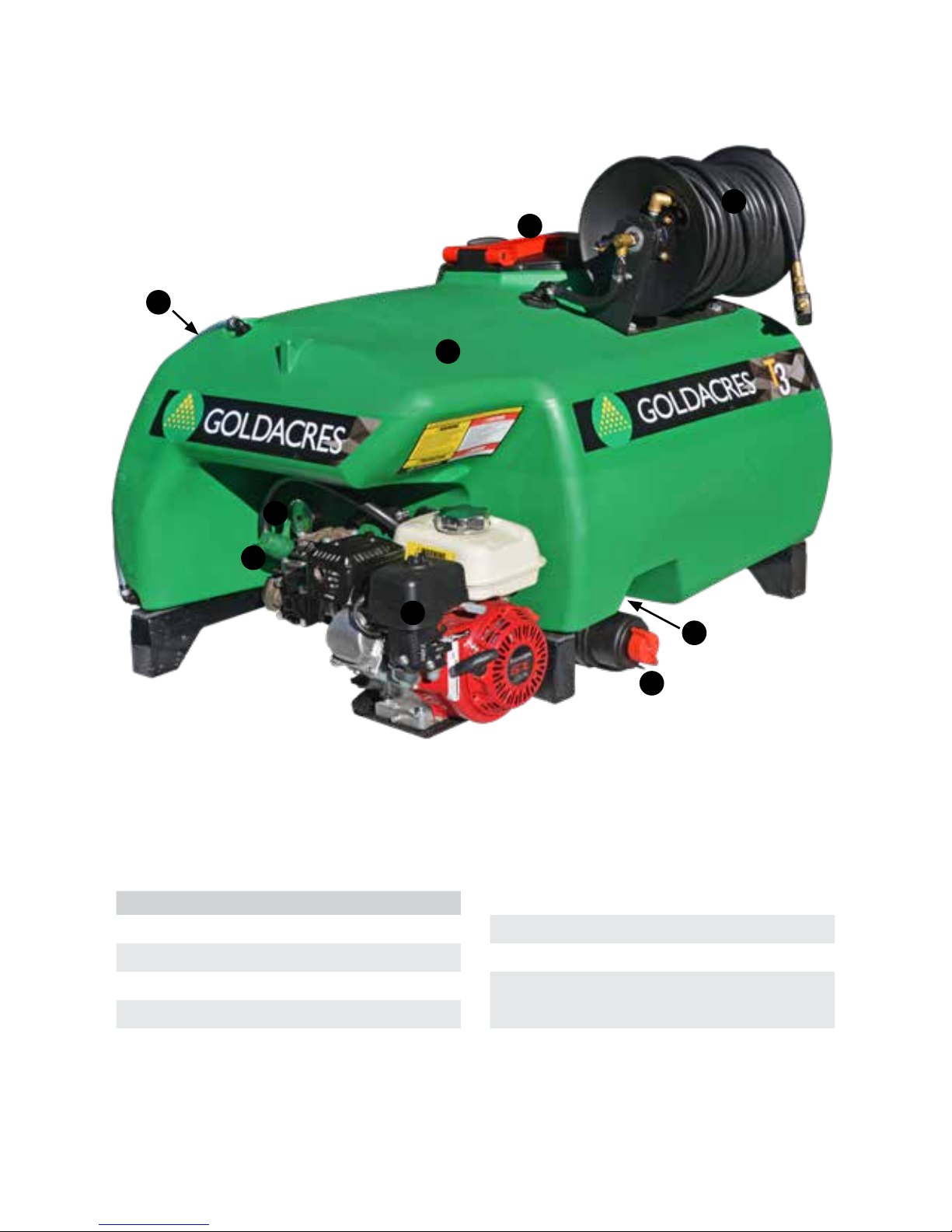
Key Features
Ref No. Function
1 Main Tank
2 Control Valve
3 Pressure Adjustment
4 Main Tank Lid
5 30m Hose Reel
6 Main Tank Drain
7 Suction Filter
8 Pump & Motor
9 Wet Sight Tube
7
8
9
1
2
4
5
6
3

6
Pre Operation
Know your sprayer
Getting to know your sprayer prior to
operation is crucial in the safe and ecient
operation of this equipment. Take the time to
familiarise yourself with all the standard and
optional components tted to your sprayer,
not only do you need to know where key
components are located on your machine you
need to become competent in the operation of
these components prior to operation. It is also
important to become familiar with common
spraying methods and common spraying
terms prior to using this sprayer for the rst
time.
Following delivery
The Goldacres Traymount sprayer has been
designed for carrying by a suitably rated
vehicle.
1. Remove from pallet (if attached) and
position on a solid, at surface.
2. Use a forklift, or other suitably rated lifting
device, to lift the sprayer to a height
suitable for the vehicle. Use support legs
to x the unit at this height.
3. Mount the Tray Mount to your vehicle.
4. Carry out pre-start operation checks for
engine and pump as per engine and pump
manuals.
5. Fill with suitable quantity of water to test
operation.
6. Follow operating instructions for controller
tted, bypass needs to be open to ensure
that engine is not started with any load.
7. With engine and pump running smoothly
at three quarter revs, close bypass and
set required pressure, then activate boom
(if tted) and then hose reel (if tted) and
check operation.
8. The TRAY MOUNT sprayer is now ready
for operation.
Removing from the Vehicle
Use the reverse of the procedure above to
remove the Tray Mount from the vehicle.
CAUTION:
Where tted remove the console from the
vehicle cabin prior to removing the Tray Mount
from the vehicle.
Tasks prior to spraying
CAUTION:
Before using this equipment with a chemical
mix, read and understand, the instructions
on the chemical label. The rst time setup
procedure should be carried out as a water
test only prior to any chemical being applied to
the tank and applied.
Following the rst time set up procedure being
followed, there are several important checks to
be carried out prior to starting spraying.
1. Inspect the sprayer to ensure there is no
damage or wear which could lead to injury,
further damage or reduce its performance.
2. Check all bolts and nuts to make sure they
are tight and secure.
3. Carry out scheduled lubrication.
4. Make sure the sprayer is securely attached
to the vehicle
5. Fill the ush water tank (where tted) and
hand wash tank (where tted) with an
appropriate amount of clean water.
6. Clean all lters and nozzles.
7. Fill main tank with a quantity (approx 10%
of total tank volume) of fresh water.
8. Test the pump with clean water. To start
the pump, start the engine at the lowest
revs possible and then gradually increase
revs until the pump reaches your desired
operating speed.
CAUTION: Do not exceed 540 RPM.
9. Check nozzle patterns for irregularities. If
there are irregularities, clean the nozzles
and replace. If the problem persists they
could be worn so remove and replace.
10. For optimal sprayer set-up, the operator
needs to be aware of the correct nozzle,
the correct speed at which to travel and
the appropriate rate per hectare to apply
the product. For this information, refer
to the chemical label, the supplier of the
product and the TeeJet catalogue.
11. Check all hoses and ttings for leaks or
damage.

7
12. Follow the chemical label and ensure that
you follow the specied mixing procedure
for addition of chemicals to main tank.
13. When mixing procedure has been
followed, ll main tank with appropriate
quantity of water required for task at hand.
14. CAUTION: Traymount sprayers tted with
manual hose reels should not exceed 160
psi maximum spraying pressure. If the unit
is tted with a Pro Reel automatic rewind
hose reel the maximum operating pressure
is 300 psi.
WARNING: When lling tanks with water, 1
litre of water will add 1 kg of weight. Some
chemicals weigh more than water, therefore
it is the operators responsibility to ensure the
loaded weight of the sprayer does not exceed
the towing and / or carrying capacity of the
vehicle.
15. You are now ready to start using the
sprayer
Operation
General
Before attempting to use your sprayer with
any chemicals, the application rate in litres
per hectare and the droplet spectrum need
to be considered. This information should be
readily available from your agronomist and by
referring to the chemical label.
NOTE: Allow the pump to agitate the tank
mixture while lling. It is normal practice to
agitate the spray mixture before spraying. The
chemicals need to mix uniformly throughout
the spray mixture in order to achieve a correct
spray application. Agitation is primarily a
function of pump capacity, such that the larger
the pump the greater the amount of bypass
and hence the greater amount of agitation for
a given spraying application.
Connections
The following steps should be followed when
connecting to a power source:
1. Ensure that the battery is 12V DC
2. Connect the red connector to the positive
(+) terminal and the black connector to the
negative (-) terminal.
Calibration
All sprayers need to be calibrated and kept
in good condition. This will ensure that the
correct rate of chemical is applied to the
target.
Follow these steps to calibrate the sprayer:
1. Measure the spray width of the nozzle on a
dry surface (in metres)
2. Spray a test area at the intended pressure
and speed. Record distance (in metres)
covered in one minute (minute)
3. Measure the nozzle output in litres over
one minute in a measuring jug (l/min)
The spray volume can be calculated by the
following formula:
Application Nozzle output (l/min) x 10,000
rate (L/Ha) = Spray width (m) x speed (m/min)
Filling
1. Add 20 per cent of the tanks volume of
clean water to the main spray tank.
2. Carefully add all chemicals (more water
may be needed in the tank initially if
adding granular or powder chemicals).
3. Add the remaining water (this will then help
to mix the chemicals).
4. Agitate with pump at operating speed
(maximum 540 RPM).
5. Check to ensure agitator is working (if
tted). There should be visible circulation
of water near the back of the tank near the
agitator.

8
After spray application
CAUTION:
Refer to chemical label for correct disposal of
chemical residue.
Drain out any chemical residue in the tank
through the drain tap.
Flush main tank:
1. With the main tank drained, rinse the
inside of the tank with clean fresh water.
As a guide, use 20% of the tanks volume
for ushing.
2. With fresh water in the spray tank, operate
the pump to clear chemical residue from
the lines, then open the boom valves to
allow the nozzles to be ushed.
CAUTION:
Refer to chemical label for correct disposal of
chemical residue.
Refer to chemical label for correct
decontamination procedure when
decontamination is required.
Transporting the sprayer
Make sure the vehicle has sucient lifting and
braking capacity to carry the sprayer.
All relevant transport regulations must be
adhered to when transporting the sprayer. (ie:
speed regulations, oversize signs, ashing
light, etc.) It is the operator’s responsibility to
know the relevant regulations. Make sure the
sprayer is securely attached to the vehicle as
shown below.
CAUTION:
Take care when reversing the vehicle with the
sprayer attached. If driver visibility is restricted
use another adult, with a clear view to the rear
of the sprayer, to give reversing directions.
CAUTION:
It is the operator’s responsibility to know the
tare weight and gross weight of the sprayer.
Contact Goldacres dealer to ascertain a more
precise tare weight for your sprayer if unsure.
If any alterations are made to the sprayer, it is
the operator’s responsibility to know the tare
weight and the gross weight of the modied
sprayer at all times.
NOTE: Store the sprayer in a suitable location
to prevent freezing. If the sprayer is to be left
where freezing may occur, cover the pump
and ow meter with a material bag and empty
pump and ow meter of all water (run the
pump dry for 15-20 seconds). Make sure any
ice has thawed before using sprayer.
Ensure the main tank and any other tanks
tted are empty.
End of Season Tasks
If the sprayer is to be stored for a long period
of time without use, there are several tasks
that need to be performed.
• Clean the sprayer thoroughly as described
under “End of Spraying Day Tasks”.
• Follow end of season storage instructions
for the engine (where tted) as per the
engine manufacturers operator manual
supplied.
• With the sprayer attached to the carrying
vehicle, carry out a thorough observation
to determine if there is any damage to the
sprayer.
• Store the sprayer in a position where it will
not be aected by frosts, and preferably
out of direct sunlight.
• Ensure the main tank and any other tanks
tted are empty.
Maintenance and
Troubleshooting
Pump Information (Diaphragm pumps)
The pump is critical to any sprayer
performance. Correct operation and
maintenance of the pump will ensure the
sprayer is able to perform to its capabilities.
Flushing the pump system with fresh water:
To ush the pump system, use the procedure
described under the using your sprayer
section of this manual for “Flushing”.
NOTE: Never overll pump with oil as damage
to seals and oil bowl may result.
The pump will perform optimally operating
between 400 and 540 RPM. 500 RPM is
approximately three quarter revs on the
engine.
At lower revs excessive pulsation will occur,
while pump and diaphragm damage can result
at higher revs.

9
Manual Controls
A general explanation of manual controller
functions are as follows:
Pressure Relief Valve
The pressure relief valve provides relief when
the pressure exceeds a pre-determined
value. Altering the adjusting stem will aect
the setting at which the relief valve will come
into operation. Turning the stem clockwise
will increase the pressure relief setting. The
pressure gauge gives indication of the delivery
pressure to the boom or gunjet.
By-Pass Valve
The By-pass valve enables all pump delivery
to bypass back to the tank. The by-pass valve
should be engaged when starting the pump
with an engine so that the engine does not
start under load. The by-pass valve should
also be engaged when wanting to agitate the
tank mixture when not spraying. To engage the
by-pass valve, pull the valve lever out. This will
cause all pump delivery to be bypassed back
to the tank.
To disengage the by-pass valve, push the
valve lever in, so that the pump delivery is
directed out to the spray lines
Boom / Attachment Levers
The boom/attachment levers (number tted
dependent on options specied) open or close
ow to the appropriate boom section/s or
attachment/s as labeled. Pull the lever to the
ON position in order to direct ow from the
pump to the required function. Push the lever
to the OFF position to stop ow going to the
attachment that is now not required.
Calibrating your sprayer
Any sprayer should be calibrated regularly
to ensure minimal error in the application
rate. A nozzle selection chart indicates what
application rates are to be expected but
variations due to nozzle wear, ground speed
error and pressure irregularities can result in
large application rate errors.
Goldacres suggest the use of a current TeeJet
nozzle selection catalogue for reference to
nozzle sizes, outputs, spray patterns and
general spraying information. For more
technical information on the function of spray
nozzles and factors aecting their performance
you can also use the TeeJet “User’s guide to
spray nozzles”.
The TeeJet nozzle selection catalogue and
Users guide to spray nozzles are available
from Goldacres dealers or as a free download
from the TeeJet website. www.teejet.com
Application Rate
The application rate depends on the following:
Spray pressure - increasing pressure
increases application rate and reducing
pressure reduces application rate
Speed of travel - increasing speed reduces
application rate and reducing speed increases
application rate
Nozzle size - increasing the nozzle size
increases the application rate.
Nozzle Selection
Refer to the chemical manufacturer’s
information to determine the recommended
application rate in litres per hectare (l/ha) for
your particular situation. Then determine the
speed in kilometres per hour (km/hr) at which
you intend to spray, taking into consideration
the ground conditions of the area to be
sprayed. Using the appropriate chart for your
boom select the most suitable nozzle to use.
Nozzle Calibration
As part of your daily sprayer calibration,
Goldacres suggests that you carry out a jug
test to ensure the spray nozzles you are using
are delivering the correct amount of chemical,
as stated in your nozzle supplier’s rate chart.
The method of carrying out the jug test is as
follows:
You will need:
• A calibrated measuring container that can
measure the medium in litres, in 10 ml
increments. e.g. 0.45 Lt.
• A timing device showing seconds.
• A pressure gauge mounted at the nozzle
tip to verify the system pressure being
delivered at the nozzle. Goldacres part
number QJ4676-1/4-NYR will mount a
suitable gauge to the nozzle body bayonet
tting. (Not including gauge).

10
NOTE: There may be a noticeable dierence
between pressure shown on main spray
pressure gauge on sprayer and the gauge
installed on the boom. This is due to pressure
loss through the circuit.
1. Check the plumbing system for kinked or
obstructed hoses and repair or replace any
hoses that restrict the normal ow of the
liquid.
2. Start your sprayer
a. For sprayers not tted with a spray
application controller, set the boom
operating pressure to the pressure at
which you expect to spray.
b. For sprayers tted with a spray application
controller, initiate a ‘self test’ procedure
and set the application rate and speed to
the settings depicted in your “Rate Chart”
at which you expect to spray.
3. Then place the jug under one of the
nozzles, for 60 seconds (exactly) and then
record the volume of liquid collected.
4. Repeat the test over a representative
sample of the jets in each boom section
5. Compare the volume collected from each
nozzle to the stated volume in your rate
chart. It should be no more than plus or
minus 10% of the volume stated in your
Nozzle Supplier’s rate chart
6. In the event that any of your nozzles do
not deliver the required volume, a further
investigation is required which may
include, but not be limited to:
a. Cleaning the nozzles, using the method
recommended by the nozzle supplier.
b. Replacing the nozzles.
c. TeeJet advise that nozzles that ow
greater than +10% of their stated volume
are ‘worn out’ and should be replaced.
d. Cleaning nozzle lters.
e. Replacing lters.
f. Replacing pump diaphragms.
g. Replacing the pump.
h. Ensuring that the application rate
required does not exceed the maximum
ow and pressure parameters of the
sprayer.
Filters
General Information
WARNING:
Ensure that operator’s wear the appropriate
PPE when cleaning lters. It is essential to
maintain all lters, and lter screens, in good
condition. Filter screens that are not regularly
cleaned can severely impede the ow and thus
aect delivery pressure.
If the screen is in any way damaged, it can
allow foreign material into the pumping
system which can result in damage to the
pump, solenoids, valves and nozzle tips. If
the screen is not properly tted, it can allow
air into the pumping lines which will reduce
the performance of the pump. The lter
screen should be cleaned after every spraying
operation. The best way to clean the lter
screen is with a soft brush or compressed air
after washing the entire chemical residue from
the pump.
Safety Shut-O Valve
The safety shut o valve enables the lter bowl
to be removed while automatically shutting o
the supply line to the lter. As the lter bowl is
removed (with the bowl cap), the valve plunger
seats so as to seal o the lter from the supply
line. Replacing the lter bowl unseats the valve
plunger and thus opens the supply line to the
lter.
Suction lter
To clean the suction lter:
1. Wear all necessary protective clothing;
2. Ensure the pump is turned o
3. Carefully unscrew lter nut and remove
bowl;
4. Remove screen and clean (with a soft
brush or compressed air);
5. Check for damage to screen, bowl,body
and ‘o’ ring;
6. Place screen back in position;
7. Make sure ‘o’ ring is in position for proper
seal;
8. Replace bowl and screw nut on;
9. Do not over-tighten nut.
 Loading...