

Goldacres Salvarani TF-EV 24 Operator's Manual
1
Foam Marker Kit
Salvarani TF-EV 24
Operator’s Manual
GA8700733 Rev0 NOV 2016

2
Contact
Goldacres
1-3 Morang Crescent,
Mitchell Park Vic 3355
P: 03 5342 6399
F: 03 5342 6308
info@goldacres.com.au
Please note: All information in this operator’s manual is based on the latest product information available at the time of printing.
The policy of Goldacres is one of continuous improvement and as such, Goldacres reserve the right to alter any specications and
designs without notice and without incurring any obligation regarding such changes. No part of this manual may be reproduced
without written permission from Goldacres. All photographs and technical information remain the property of Goldacres.
Foam Marker .........................3
Introduction ..........................3
Installation Foam Marker ...............7
Use of Foam Marker ...................9
Maintenance Foam Marker .............9
General Rules of Foam Marker .........11
Parts ...............................15
3
Foam Marker
2
4
6
8
10
12
14
16
18
20
22
Lt
1
2
3
4
5
6
7
7
8
9
Use & Maintenance
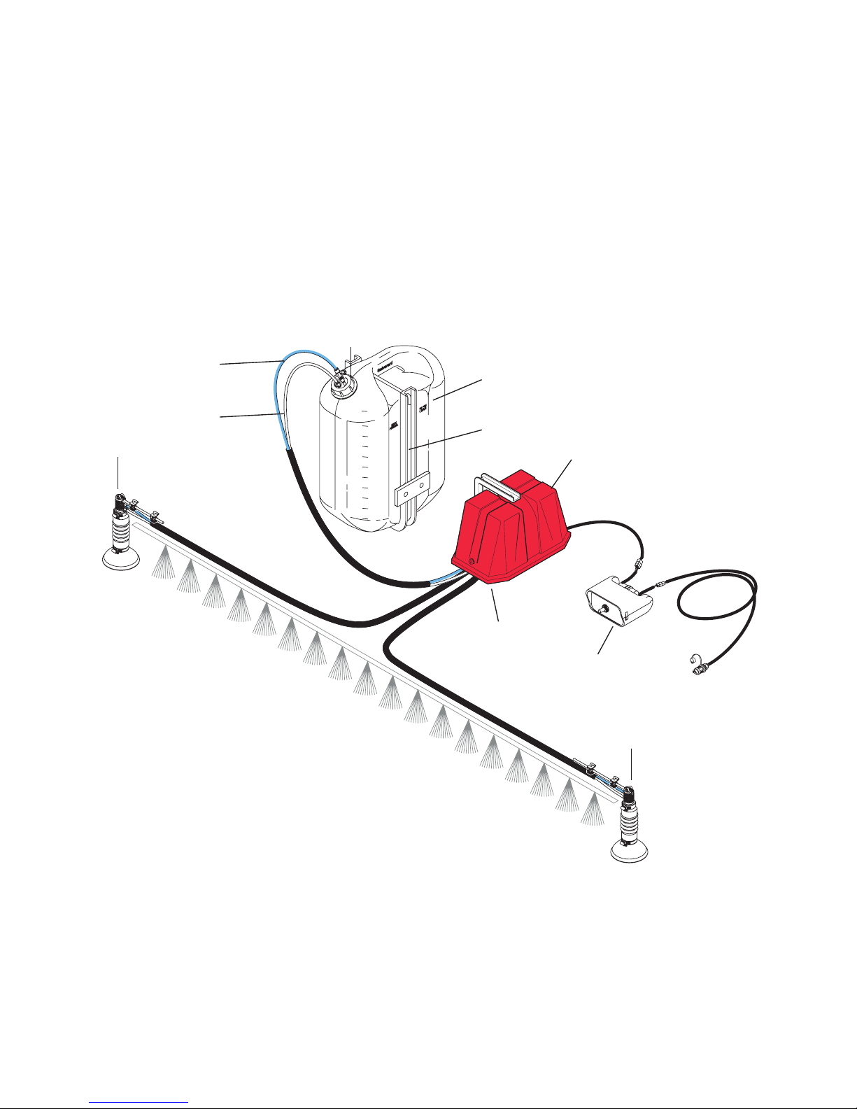
1. 1-Air compressor 12 V.D.C
2. Distributors with electrovalves
3. Liquid foaming agent tank
4. Tank frame
5. White tube air
6. Blue tube liquid
7. Foam diusers for foam formation
8. Control panel
9. Cap with safety valve
Introduction
Foam Marker Description (Fig. 1)
The foam marker is an equipment used to
mark the area of ground that is being worked,
through foam. The foam is obtained mixing
the air with water and liquid foam solution.
The foam falls on the ground at regular
intervals and creates a demarcation line which
marks the area of the worked ground. The
foam marker can be xed onto all sprayers,
pneumatic and centrifugal manure distributors,
seeders and in general when precise working
is required. Fig.1 shows the equipment and its
components.
4
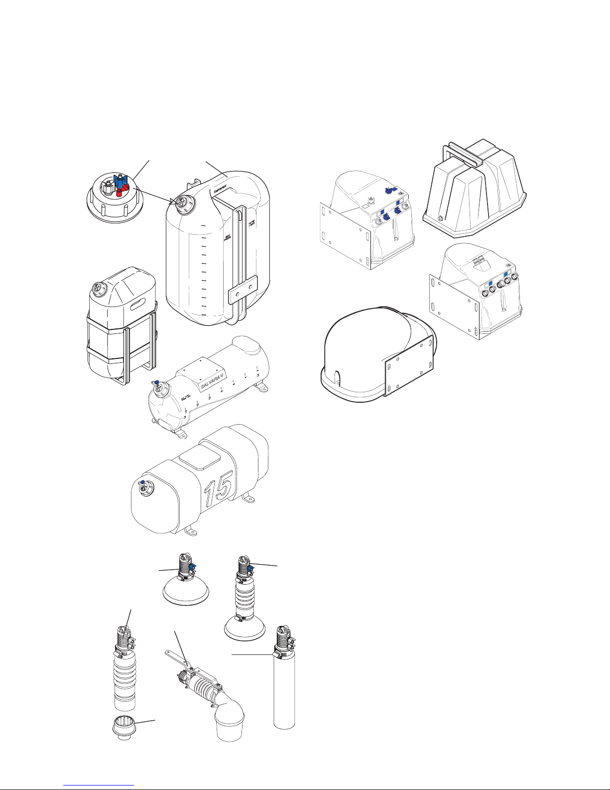
Liquid Foaming Agent Tank (Fig. 2)
The tank contains the solution created by
water and the foam solution (Fig.2-1). It
has a cap with safety valve which limits the
maximum pressure inside the tank at 0,75 bar
( Fig. 2-2).
Material of manufacture: polyethylene.
Compressor Block (Fig. 3)
It supplies the necessary pressure to the unit
to generate the foam bubbles. The group
includes the CM 40 membrane compressor
and electric valves: two for liquid and one
or two valves (relating to models) are for air
control.
Air-liquid Foam Diuser/ Mixer (Fig. 4)
The diuser mixes the compressed air with the
foaming liquid solution, creating foam bubble
which falls on the ground (Fig. 14). There are
two versions : the vertical foam diuser (Fig.1-
1,2,3 and 4) and the horizontal version (Fig.4-
5). Possible congurations for the vertical foam
diuser:
1. body only with bell: medium foam size
2. body with short diuser and conic
reduction : small foam size suitable
for turf/golf applications or oating on
vegetation
3. body only with short diuser: standard
foam size
4. body with short diuser and bell :
maximum foam size
2
4
6
8
10
12
14
16
18
20
22
Lt
Fig. 2
Tank 57 l.
Tank 16 l.
Tank 24 l.
1
2
Fig. 3
TF 2486
TF EV
TF EX
TF EC
Fig. 4
2
5
3
4
6
1
5
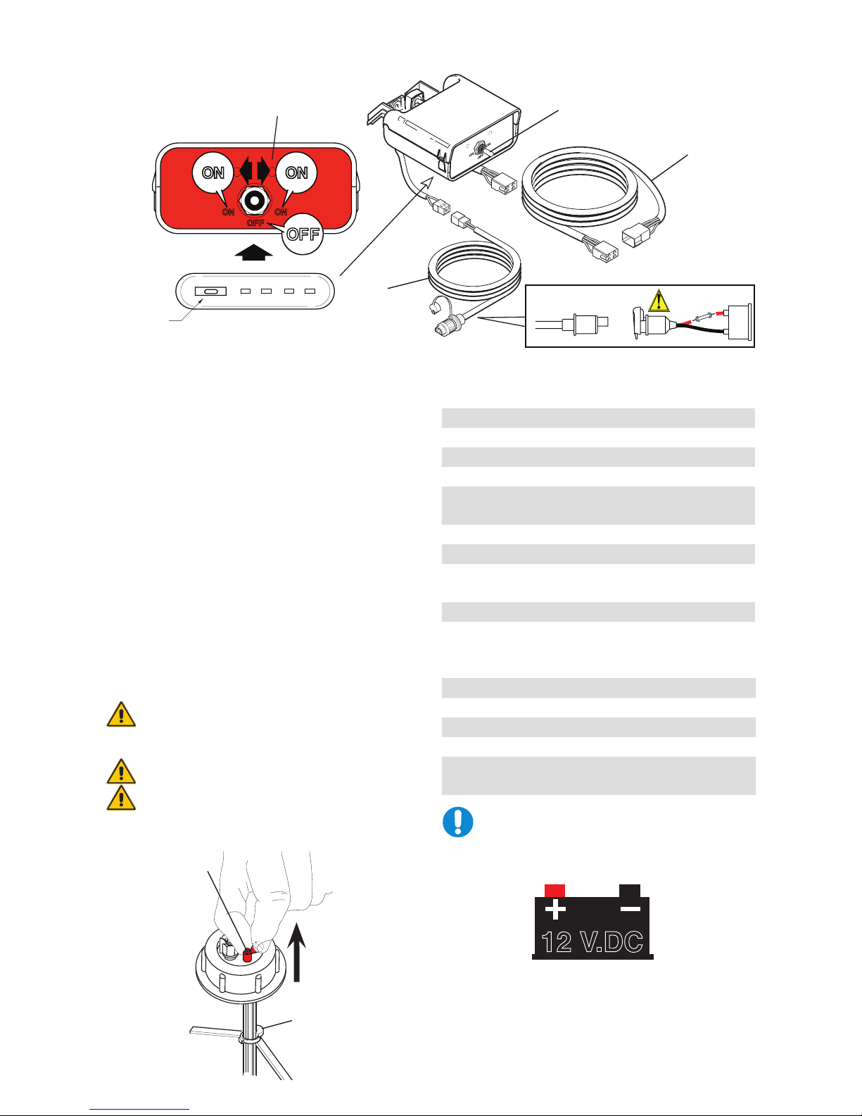
Control Panel (Fig. 5)
It allows to select (Fig.5-1) the side from which
the foam bubble will exit. The feeding cable
(Fig. 5 -2) and the connection cable to the
compressor (Fig.5-3) are included.
Safety System (Fig. 6)
A safety valve has been installed on the tank
cap (Fig. 6 - 1) and it opens at a pressure
of 0,8 bar. This system is necessary in case
of hose obstruction, in order to avoid that
pressure rising inside the tank causes its
break. The tank cap has a safety stop (Fig.
6-2) to prevent its ejection, in case of opening
under pressure. Before removing the cap,
discharge the residual pressure by manually
operating the relief/safety valve (Fig. 6 – 1).
Avoid removing the cap before having
discharged every pressure residue in
the container.
Do not remove the cap safety stop.
Do not tamper with the safety valves.
Technical Data Table
Feeding voltage 12÷14 Vdc
Absorbed current 9,5 A
Work pressure 0,75 bar
Maximun pressure 1 bar
Noise level at a distance of 1m
and 1,6m H
76 dbA
Work temperature -10 ÷ 50 C°
Storage temperature -10 ÷ 50 C°
Maximun humidity (not
condensed)
95 %
Net weight no a 23 Kg
Tank models
Mod. Capacity Ixhxp
EC/EV/EX 24 l 355x525x240
TF-24(inox) 24 l 234x673x235
TF-57 57 l 328x800x300
TF-16 16 l 210x540
Make sure that the electric battery of
the vehicle (tractor) supplies a voltage
of 12 V.
FUSE
15
15
Fig. 5
FUSE 20A
IST 052
+
-
12 VDC
1
2
4
3
12 V.DC
Fig. 6
1
2
 Loading...