

Goldacres Pro-Reel Operator's & Parts Manual
1
Pro-Reel
Operator’s & Parts Manual
50m - GA4904585
100m - GA4904584
150m - GA4906985
GA8700158 REV 6 MAY 17

2
General Information
and Specs ............................3
Specications ........................3
Pro-Reel Dimentions ...................3
Key Features .........................4
Set up ...............................5
Connecting to a power source ............5
Connecting to a water source ...........5
Connecting the ENGINE OFF ............5
Operation
Prepare for use .......................5
Instructions ..........................6
Goldacres Pro-Reel
®
Single Reel Controller
Conguration .........................7
Supplying Power to the Remote Unit and
the Pro-Reel
®
Control Box. ..............8
Pro-Reel
®
Control Box Conguration .....8
Restoring a Control Box to factory default
settings ..............................9
Troubleshooting. .....................10
Maintenance ........................11
Troubleshooting ......................12
Pro-Reel Assembly ...................13
Hose Guide Assembly .................14
Control Box, Antenna & Gun Mount .....15
100m Electric Motor & Guard Mounting ..16
Hose Reel 100m ......................17
150m Electric Motor & Guard Mounting ..18
Hose Reel 150m ......................19
Electrical Schematic ..................20
Turbo 400 spray gun ..................21
Safety Decals ........................22
Safety ..............................23
The Operator ........................23
Safety Precautions ...................23
Personal Protective Equipment (PPE) ....24
Warranty ............................24
Goldacres Warranty Statement .........25
Terms and Conditions .................26
NOTE: Front Page, Spray gun is shown, but is
an option only.
Contact
Goldacres
1-3 Morang Crescent,
Mitchell Park Vic 3355
P: 03 5342 6399
F: 03 5342 6308
info@goldacres.com.au
Please note: All information in this operator’s manual is based on the latest product information available at the time of printing.
The policy of Goldacres is one of continuous improvement and as such, Goldacres reserve the right to alter any specications and
designs without notice and without incurring any obligation regarding such changes. No part of this manual may be reproduced
without written permission from Goldacres. All photographs and technical information remain the property of Goldacres.
3
General Information
and Specs
General
The Pro-Reel hose reel is electrically driven
with 12V from the vehicle battery. Up to
150 metres of hose can be tted and a
gunjet provides for even and accurate spray
application.
Single or multiple units can be linked to an
appropriate tank and pump conguration.
Chassis:
The chassis is an all steel construction, that is
fully welded for superior strength. The chassis
is shot blasted, primed and then protected
by the Goldacres paint process for excellent
chemical resistance and durability.
Paint Colours:
Steel work:
G13 Dark Green
Specications
Dimensions
See page 11
Hose size
10mm
Hose length
50,100,150 metres
Pump
requirements
Min 20 l/min
Connections
50 Amp Anderson plug
(supplied)
Control type
Remote
Drive
12V electric
448
671
901
445
352
84
239
9
12
3
2
5
C
D
4
6
7
8
A
B
2015 100m Pro Reel Assembly
1-3 MORANG CR
MITCHELL PARK 3352
PH: 03 53426399
FAX: 03 53426308
GOLDACRES
TITLE:
671
901
5
C
D
4
6
7
8
A
B
2015 100m Pro Reel Assembly
1-3 MORANG CR
MITCHELL PARK 3352
PH: 03 53426399
FAX: 03 53426308
GOLDACRES
TITLE:
445
352
84
239
9
12
C
B
A
2
1
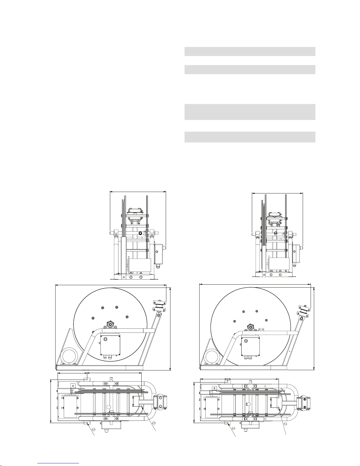
446
721
969
239 445
85
10.5
9.0
352
721
969
239 445
85
10.5
9.0
352
Pro-Reel 50
Pro-Reel 100
Pro-Reel 150
Pro-Reel
Dimentions

4
Key Features
No Part No Function
1 Hose Feeder
2 GA5063500 Electrical Control Box, Antenna, Remote and loom (complete assly)
3 GA5052970 Electrical motor
4 GA5023475 Spray Gun
5 V Belt Adjusters
6 GA5061710 Remote Aerial
7
Anderson Plug
8 GA 5061715 Remote Control Black
9 GA5061720 Remote Control Grey
10 GA5072390 PCB Board (457PN3-1000)
11 GA5072380 Switch Circuit Breaker
12 GA5053245 50amp Anderson Plug
13 GA5072541 Con guration Cable, 2.5mm Jack
14 GA5072545 Switch, Manaul over-ride
2
3
4
1
6
5
14
7
13
8
9

5
Connecting to a power
source
The following steps should be followed when
connecting to a power source:
1 Ensure that the battery is 12V DC and that
a 40amp, circuit breaker is tted to the
positive lead at the battery.
2. Using the Anderson plug supplied,
connect the red connector to the positive
(+) terminal and the black connector to the
negative (-) terminal. It is recommended to
get an electrician to wire this unit.
WARNING: Do not use the nominally 1.5V
Lithium cells in the remote unit as these
are in fact above 1.8V when new, and may
result in damage to the remote unit. Use
only high quality 1.5V alkaline cells for good
performance and product reliability.
Connecting to a water
source
The following steps should be followed when
connecting to a water source:
1 The ½” supply hose must have a pressure
rating that exceeds the pump pressure,
needs to be connected up to the hose reel.
2. Slide the supplied nut onto the hose, then
slide the olive on so there is about 4-5mm
of hose coming through the olive.
3. Fit the hose and tighten the nut to the ProReel.
Connecting the Engine
Remote Shutdown
WARNING: Do not have any power connected
for this operation.
1. Disconnect the 6 pin plug from the control
box.
2. Open the female plug that is on the electric
motor side. Remove the seal from the “E”
port
3. With a 3mm blue wire, t the supplied
green seal and crimp on the terminal pin.
4. Fit wire into the “E” port on the 6 pin plug
and press home until you feel a click. The
pin is seated. Close the cover on the plug.
5. Fit the two plugs together and ensure they
seat correctly.
6. Feed the blue wire to the pump motor ON
switch making sure that it is out of the way
of moving parts and will not get hot from
any parts of the engine.
7. Fit the wire to the earth wire on the engine
ON/OFF switch.
Operation
Prepare for use
1. Inspect the unit to ensure there is no
damage or wear which could lead to injury,
further damage or reduce its performance.
2. Check all hoses and ttings, including
spray gun, for leaks or damage.
3. Check all bolts and nuts to make sure they
are tight and secure.
4. The Pro-Reel hose reel is operated by
remote control and when tted should be
in a location which is easily accessible
with clearance between the reel and all
other items.
PROREEL CABLE SIZE CHART @ 12vdc / 30 amps
30 amp overload protection
Distance from battery to Anderson plug (mts) 1 2 5 7.5 10
Cable in mm
x2 2.5 6 16 25 25
AWG 13 10 6 4 3
Set up
6
Instructions
CAUTION: Keep hands, feet,hair and clothing
away from all moving parts to prevent injury.
NOTE: Hose will un-wind with a small amount
of restriction when pulled out by hand
Operation
1. While connected to a power source, the
unit is always powered.
2. Remove the linch pin and check the spray
gun.
3. Test the remote and manual rewind
functions. The manual “REWIND” button
is located on the control box.
4. Unwind the hose (taking care to not overrun the hose)
5. The hose can then be wound in by
pressing the “REWIND” button on the
remote control.
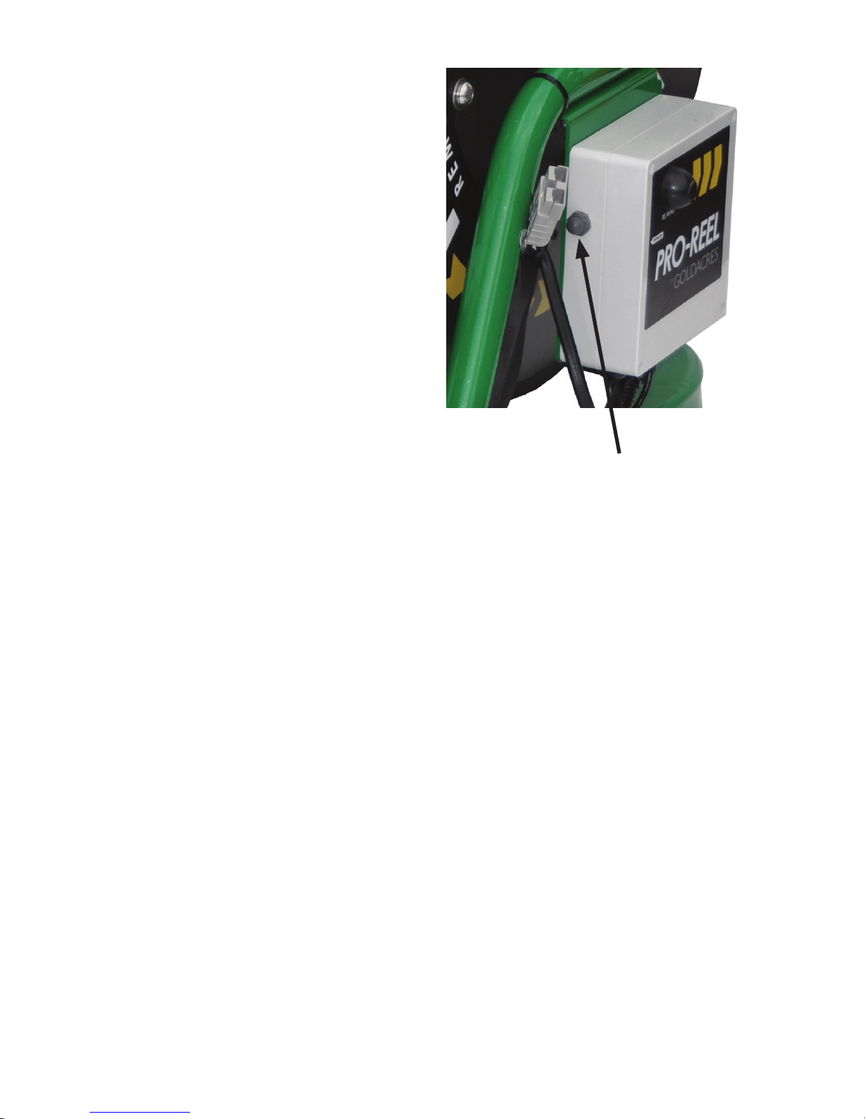
6. If the reel stops turning due to a hose jam
DO NOT continue to push the button or
damage may occur. Clear the cause of the
jam prior to further operation. If the remote
does not work after the jam, the control
box overload may need to be reset. Press
to reset.
7. When nished, rinse the line out with fresh
water.
8. Retract all the hose and remount the spray
gun.
9. When complete, disconnect the power at
the anderson plug.
Current overload reset button
7
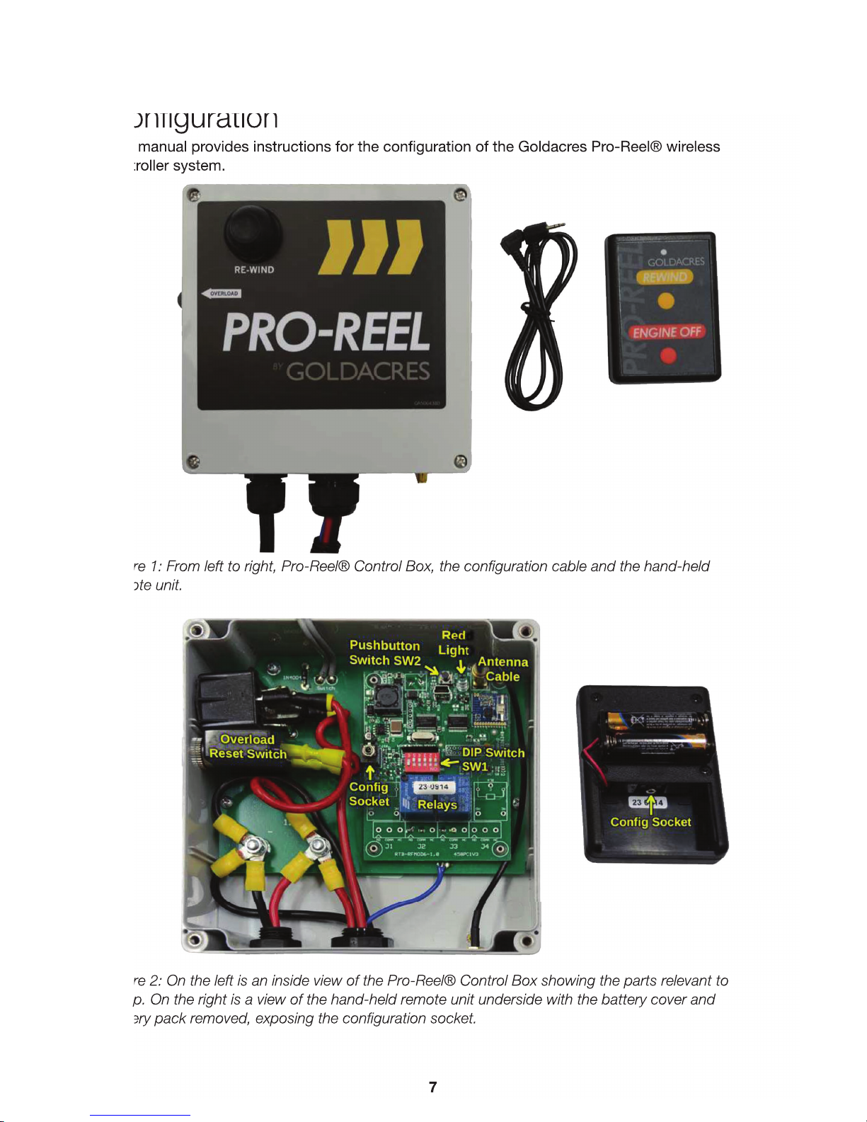
Goldacres Pro-Reel® Single Reel Controller
Con guration
This manual provides instructions for the con guration of the Goldacres Pro-Reel® wireless
controller system.
Figure 1: From left to right, Pro-Reel® Control Box, the configuration cable and the hand-held
remote unit.
Figure 2: On the left is an inside view of the Pro-Reel® Control Box showing the parts relevant to
setup. On the right is a view of the hand-held remote unit underside with the battery cover and
battery pack removed, exposing the configuration socket.

8
Supplying Power to the
Remote Unit and the
Pro-Reel® Control Box.
Refer to gure 2 on page 1 for information on
the locations of the various parts.
CAUTION: Ensure that battery polarity is
correct when inserting batteries into the
remote unit battery
compartment.
WARNING: Do NOT use the nominally 1.5V
Lithium cells in the remote unit as these are in
fact above
1.8V when new and may result in damage to
the remote unit. Use only high quality 1.5V
alkaline cells for
good performance and product reliability.
For the remote unit, ensure that a suitable pair
of 1.5V cells are inserted correctly into the unit.
The battery cover
is on the rear of the unit at the base. Two size
‘AAA’ cells will be required. Spring contacts in
the battery holder
always connect to the negative ends of the
cells. Also under the battery cover can be
found the con guration
socket (see gure 2 on page 1) which is a
2.5mm socket. This is used to connect the
remote unit and the control
box together with the supplied con guration
cable to enable programming of remote unit
buttons to control box
relays. The battery holder must be removed in
order to access the con guration socket of the
remote unit, but the
batteries should be left in the holder to ensure
that the remote unit is still powered.
The Pro-Reel® control box should already
be suitably con gured with 12V DC vehicle
battery power.
Pro-Reel® Control Box
Con guration.
Con guration of the system is required if
replacing a damaged or lost remote (hand held
transmitter) unit, since
each transmitter and receiver are paired using
unique identi er codes.
2.1 Con guring a Remote Unit to control a
Control Box’s relays.
In the event that a remote unit must
be replaced or a new one added to an
existing con guration, the following steps
will enable a new remote unit to be used
with an existing control box. The location
of relevant parts can be identi ed using
gure 2 on page 1.
CAUTION: Do not touch any component in the
control box except those parts referred to
in the following procedure.
1. Check that the DIP switch (SW1 in the
control box) is set as follows:
Figure 3: DIP Switch (SW1) setting. Note that
all switches are in the OFF position except
switch 6.
2. Connect the con guration cable between
the remote unit and the control box via the
con guration sockets. If done successfully,
the red light of each unit will light up
continuously. If both lights do not ensuring
that neither light is lit and then reconnect
the cable. (If, after several attempts to
establish the con guration connection, the
lights do not both remain lit, then consult
the troubleshooting section, section 3, of
this manual.)
3. Once the red lights of both the remote unit
and the control box remain lit while the
con guration cable is connected, press
and hold push-button switch, SW2, in the
control box until the control box’s red light
turns o , then release the push-button
switch. The control box’s red light should
remain o but the remote unit’s red light
should still be on.
4. On the remote unit, depress the Rewind
button. The light on the remote unit
should turn o and the light in the control
box should very brie y turn on and then

9
immediately o again.
5. Now depress the Engine O button on
the remote unit. The light on the remote
unit will turn back on and the light in
the control box should also switch on
and remain on. This indicates that the
conguration is complete.
6. Disconnect the conguration cable and
test the system by pressing each of the
two remote unit buttons in succession to
observe whether or not they perform as
required.
This completes the setup and test of a hand-
held remote unit with a Pro-Reel® control box.
If there are problems
with operation of the system, the control box
can be restored to factory settings as follows:
Restoring a Control
Box to factory default
settings.
Do not connect the conguration cable since
this operation is done to the control box alone.
1. Press and hold down the control box
push-button switch, SW2, for at least 12
seconds. Time this by counting slowly
to 12, during which time the red light will
switch on and o various times and for
various durations. When the required time
has elapsed, the light will blink on and o
continuously at a fast rate (ashing about
twice per second). This means that 12
seconds has elapsed.
2. Release the push-button switch. The
control box’s factory settings have now
been fully restored.
3. Perform the conguration process again,
as described in section 2.1, if required.
The control box factory restore process will
always restore settings back to their factory
defaults. If any settings
have been altered for an alternative mode of
operation, these will have to be congured
again.
Troubleshooting.
The following list of items may be used to
aid in fault nding if the control box fails to
respond to remote unit transmissions. Use
this when the control box is opened for
conguration of a new or replacement remote
unit if the equipment fails to perform correctly
upon conguration.
NOTE: Do not attempt repairs to the control
box internal circuitry or associated wiring
looms, connectors and external associated
equipment. This list is only intended as a basic
guide to resolve any minor issues or to simply
locate potentially major issues that may result
from wear of the equipment. Refer all servicing
to the product supplier.
CAUTION: Do not make physical contact
with any of the components in the control box
except to connect the conguration cable
to the conguration socket, to set the DIP
switch (SW1) as described in section 2.1 (if
it has been altered) and to press the pushbutton switch (SW2) as described in section
2.1. Contamination of circuitry or electrostatic
discharge into the circuit may result in
permanent damage to the control box.
1 Check control box power as described in
section 1. Ensure that adequate vehicle
battery power is available to the Pro-
Reel® control box and that it is correctly
connected. The system is designed for
12V DC automotive power supplies.
2. Press and release the Pro-Reel® control
box current overload reset button (on the
left side of the control box exterior) in case
an overload has occurred. If the unit now
works, it is advisable to inspect the system
to discover, if possible, what caused the
overload and rectify the problem.
3. Check that the hand-held remote unit
batteries are correctly oriented and that
they are serviceable. Replace them if
uncertain about their age. Never mix old
and new batteries or batteries of dierent
types. When replacing batteries, always
replace both with a pair of the same type
of batteries. Mixing batteries can result in
damage to the remote unit if either battery
leaks. Refer to section 1 regarding the
correct selection of battery types.
 Loading...