

Goldacres Batchmate Operator's & Parts Manual
1
Batchmate
Operator’s & Parts Manual
GA4914520
GA8700153 REV 4 OCT 16

2
Contact
Goldacres
1-3 Morang Crescent,
Mitchell Park Vic 3355
P: 03 5342 6399
F: 03 5342 6308
info@goldacres.com.au
Disclaimer
Any advice or recommendations given by Goldacres, Goldacres’ dealers, or employees is given in good faith and provided based
on the best information available to us. No liability or responsibility is accepted or implied as a result of any information or advice
tendered in this operating manual or by Goldacres its agents or employees. The end user accepts all responsibility arising from
that advice. No part of this manual may be reproduced without written permission from Goldacres. All photographs and technical
information remain the property of Goldacres.
Operator’s Manual Part Number: GA8700153
General Information and Specs ..........3
Dimensions ..........................3
Key Features .........................4
Operation ............................5
Prepare for use .......................5
Instructions ..........................5
Add Granular chemical to main tank ......5
Add chemical from Chem Probe
- Empty tank ..........................5
Add chemical from Chem Probe
- Full tank ............................6
Transfer to Sprayer ....................6
Tank Cleaning ........................7
End of day tasks ......................7
Drain the main tank ....................7
Engine & Pump
Safety Alert ...........................8
Start Up & Installation ..................8
Engine & Pump - Troubleshooting ........9
Engine & Pump Warranty ..............10
Maintenance ........................11
Honda Engine .......................11
Air Cleaner ..........................12
Fuel ................................12
Starting the Engine ...................12
Operation ...........................13
Stopping the Engine ..................13
Maintenance ........................13
Maintenance Schedule ................15
Transport / Storage ...................15
Troubleshooting ......................16
Specications .......................16
Wiring Diagram ......................17
Main Tank & Frame ...................18
Washdown Gun ......................19
Hand Wash Tank .....................20
Tank inlet & Drain. . . . . . . . . . . . . . . . . . . . .21
Pre-assembled Rinse Valve Station ......22
Pump Plumbing Mounting .............23
Pump Plumbing Assembly .............24
Venturi,Chem Probe Assembly ..........25
Tank Rinse Elbow ....................26
Drain Elbow Assembly ................27
Main Tank Drain ......................28
Large Lid, Drum Rinse Assembly ........29
Small Lid, Drumbuster Assembly ........30
Safety Decals ........................30
Safety ..............................31
The Operator ........................31
Safety Precautions ...................31
Personal Protective Equipment (PPE) ....32
Goldacres Warranty Statement .........33
Terms and Conditions .................34
3
General Information
and Specs
General
The Batchmate allows you to mix and agitate
chemical in preparation for loading into your
sprayer – taking the work out of loading
powders or granules and speeding up your
sprayer ll cycle.
Fitted with a high capacity 3” poly pump and
powerful twin agitation system, the Batchmate
delivers maximum chemical agitation and high
tank ll rates to add speed and eciency to
sprayer loading tasks.
Chassis:
The chassis is an all steel construction, that is
fully welded for superior strength. The chassis
is shot blasted, primed and then protected
by the Goldacres paint process for excellent
chemical resistance and durability.
Paint Colours:
Steel work: G13 Dark Green
Tank:
All tanks are constructed from UV resistant
polyethylene. Polyethylene tanks have a very
high chemical resistance.
Due to the rotomoulding process, there can be
a variance in the overall dimensions of the tank
which in turn results in variations to the tank
capacity. For this reason, calibration markings
should be used as a guide only.
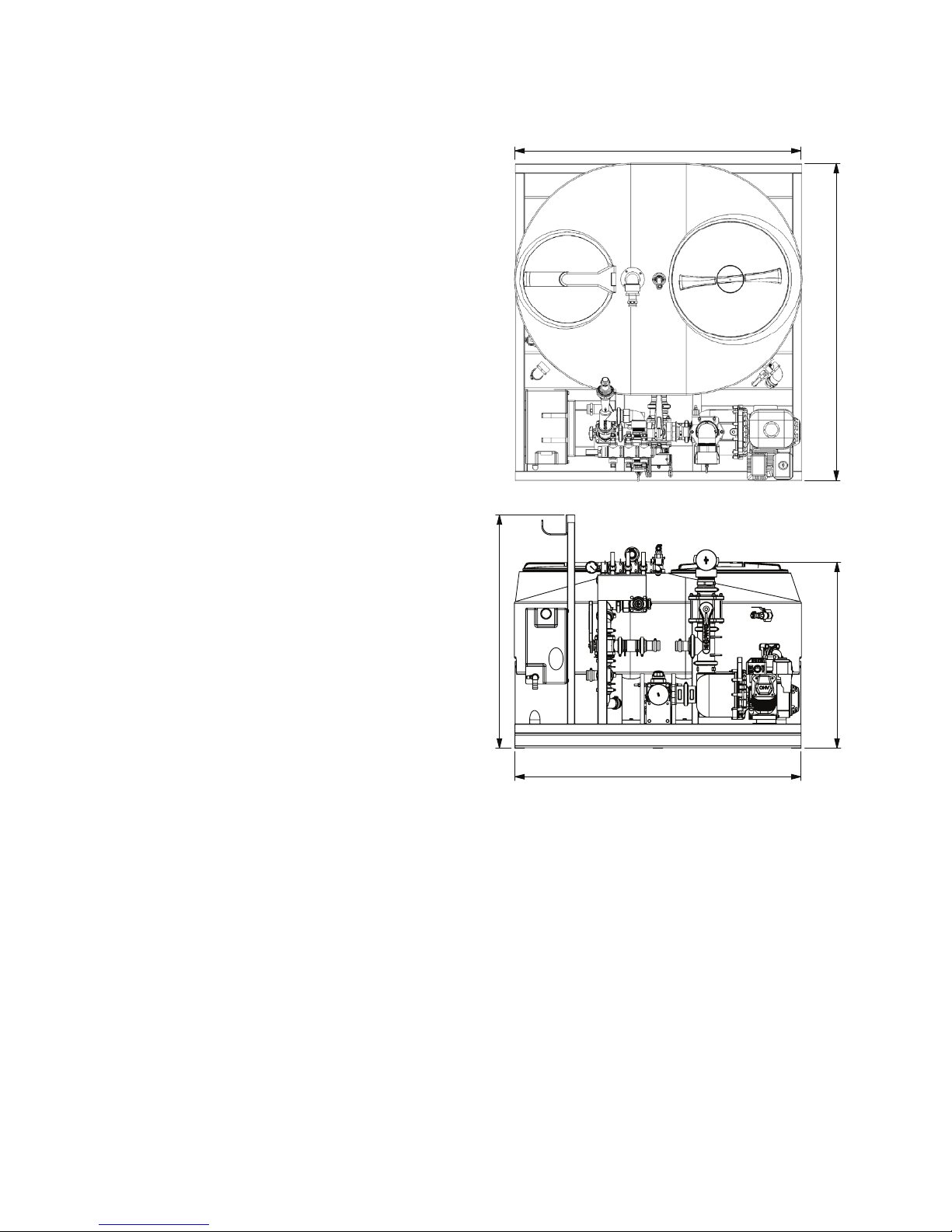
Dimensions
4
1229
1507
981
1670
1507
5
4
6
7
8
4
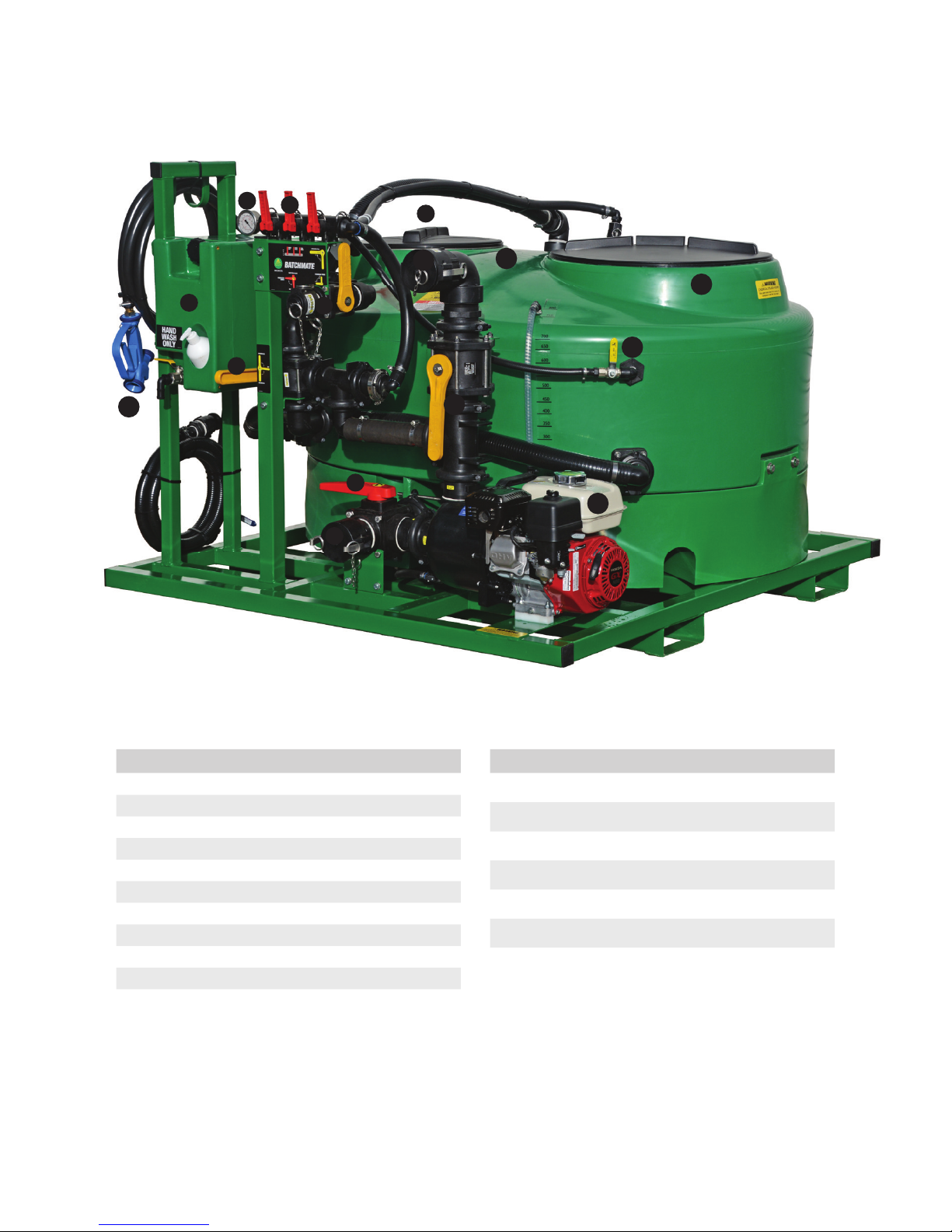
Key Features
Ref No Function
1 Suction Valve
2 Suction Valve Inlet
3 Chem Probe Coupling
4 Agitator, Venturi, O Valve
5 Fresh water hand wash
6 Main Tank Drain (not Shown)
7 Pressure Gauge
8 Rinse Valve Station
9 Drumbuster
10 Tank Rinse
Ref No Function
11 Drum Rinse
12 Drum Rinse Tap
13 Sprayer Fill outlet
14 Sprayer Fill Valve
15 Honda Engine
16 Aussie Pump
17 Wash down hose
1
3
4
8
9
10
11
12
13
14
15
17
7
5
2
16

5
Operation
Prepare for use
1. Inspect the unit to ensure there is no
damage or wear which could lead to
injury, further damage or reduce its
performance.
2. Check all hoses and ttings, including
rinse gun, for leaks or damage.
3. Check all bolts and nuts to make sure they
are tight and secure.
4. Check all ball valves and taps are easy to
move.
5. Check engine as per included
manufacturer’s operator manual.
6. Check pump as per included
manufacturer’s operator manual.
Instructions
CAUTION: Do not run pump dry as this may
cause damage to the pump.
CAUTION: Never leave the “AGITATOR
VENTURI OFF VALVE” in the OFF position
when the pump is running
NOTE: Ensure you operate the unit on level
ground to prevent oil alert being activated.
NOTE: Only clean fresh water FROM WATER
SOURCE should be used for rinsing drums in
the DRUM RINSE.
If the chemical is to be added through the
Chemical Probe connection, this can be done
during the tank lling process or after the tank
has the required amount of water.
Add Granular chemical
to main tank
1. Follow steps in “Prepare for use”
instructions as above.
WARNING: PPE must be on during this
procedure.
2. Remove quick release coupling cap from
the Suction Valve inlet
3. Connect suction hose to the Tank Fill Inlet.
4. Turn the SUCTION VALVE to the FROM
WATER SOURCE position. Lever cross
ways.
5. Ensure the SPRAYER FILL ball valve is in
the OFF position, horizontal.
6. Ensure the ball valve on the left is in the
AGITATOR ON position.
7. Follow instructions for use of the pump
for lling as per pump manufacturers
operators manual included.
8. Start the engine.
9. Fill the tank with approx 300L of fresh
water, or to just above the agitator ll
ports.
10. Turn the SUCTION VALVE to FROM
BATCHMATE so the water is cycling
through the tank.
WARNING: PPE Cut and Puncture
resistant gloves to Level 4 should be worn.
11. Open the smaller lid on the main tank and
add the chemical required by tipping in or
use the Drumbuster implement to empty
the drums.
12. Close the lid of the tank.
13. Turn the SUCTION VALVE to the FROM
WATER SOURCE position. Lever cross
ways.
14. To rinse the drums, if required, open the
red ip valve DRUM RINSE, then open
the large lid of the tank, cover the nozzle
with the drum then turn on the Drum Rinse
Tap to rinse, when nished turn the tap o
before removing the drum. When drums
are rinsed, replace the lid on the tank and
turn o the DRUM RINSE ip valve.
15. When the water level is reached,turn the
SUCTION VALVE to FROM BATCHMATE.
This will keep the chemical mixed and
ready to be transferred to a sprayer tank.
Add chemical from Chem
Probe - Empty tank
1. Follow steps in “Prepare for use”
instructions as above.
WARNING: PPE must be on during this
procedure.
2. Remove quick release coupling cap from

6
the Suction Valve inlet.
3. Connect suction hose to the Suction Fill
Inlet.
4. Turn the SUCTION VALVE to the FROM
WATER SOURCE position. Lever cross
ways.
5. Ensure the SPRAYER FILL ball valve is in
the OFF position, horizontal.
6. Ensure the ball valve on the left is in the
VENTURI ON position.
7. Attach the Chem Probe hose to the
camlock coupling on the front of the
BATCHMATE.
8. Follow instructions for use of the pump
for lling as per pump manufacturers
operators manual included.
9. Start the engine.
10. When the water is owing through, open
the ball valve CHEMICAL PROBE and
empty the drums. Close the valve when
drums are empty.
11. To rinse the drums, open the red ip valve
DRUM RINSE, then open the large lid of
the tank, cover the nozzle with the drum
then turn on the Drum Rinse Tap to rinse,
when nished turn the tap o before
removing the drum. When drums are
rinsed, replace the lid on the tank and turn
o the DRUM RINSE ip valve.
12. When the required amount of water has
been reached, turn the SUCTION VALVE
to FROM BATCHMATE.
13. Turn the left valve to AGITATOR ON. This
will keep the chemical mixed and ready to
be transferred to a sprayer tank.
Add chemical from
Chem Probe - Full tank
1. Follow steps in “Prepare for use”
instructions as above.
WARNING: PPE must be on during this
procedure.
2. Remove quick release coupling cap from
the Suction Valve inlet.
3. Connect suction hose to the Suction Valve
Inlet.
4. Turn the SUCTION VALVE to the FROM
WATER SOURCE position. Lever cross
ways.
5. Ensure the SPRAYER FILL ball valve is in
the OFF position, horizontal.
6. Ensure the ball valve on the left is in the
AGITATOR ON position.
7. Follow instructions for use of the pump
for lling as per pump manufacturers
operators manual included.
8. Start the engine.
9. When the required amount of water has
been reached, turn the SUCTION VALVE
to FROM BATCHMATE.
10. Move the ball valve on the left to VENTURI
ON position.
11. Attach the Chem Probe hose to the
camlock coupling on the front of the
BATCHMATE.
12. When the water is owing through, open
the ball valve CHEMICAL PROBE and
empty the drums. Close the valve when
drums are empty.
13. To rinse the drums, open the red ip valve
DRUM RINSE, then open the large lid of
the tank, cover the nozzle with the drum
then turn on the Drum Rinse Tap to rinse,
when nished turn the tap o before
removing the drum. When drums are
rinsed, replace the lid on the tank and turn
o the DRUM RINSE ip valve.
14. Turn the left valve to AGITATOR ON. This
will keep the chemical mixed and ready to
be transferred to a sprayer tank.
Transfer to Sprayer
1. Follow steps in “Prepare for use”
instructions as above.
2. Remove quick release coupling cap from
the Sprayer Fill outlet
3. Connect pressure hose to the SPRAYER
FILL outlet point and t the other end to
the sprayer inlet point.
4. Turn the SUCTION VALVE to the FROM
BATCHMATE position.
5. Ensure the SPRAYER FILL ball valve is in
the ON position, vertical.

7
6. Ensure the ball valve on the left is in the
OFF position.
7. Start the engine.
8. Chemical will start to be transfered to the
sprayer tank. When tank is empty, stop
the engine, close all valves.
Tank Cleaning
1. Follow steps in “Prepare for use”
instructions as above.
2. Remove quick release coupling cap from
the Suction Valve inlet.
3. Connect the fresh water suction hose to
the Suction Valve Inlet.
4. Turn the SUCTION VALVE to the FROM
WATER SOURCE position. Lever cross
ways.
5. Ensure the SPRAYER FILL ball valve is in
the closed position, horizontal.
6. Ensure the ball valve on the left is in the
AGITATOR ON position.
7. Follow instructions for use of the pump
for lling as per pump manufacturers
operators manual included.
8. Start the engine.
9. Turn on the Tank Rinse Valve to clean the
main tank. Run for at least 5 minutes.
10. After about 2 minutes, move the ball valve
on the left to VENTURI position.
11. Attach the Chem Probe hose to the
camlock coupling on the front of the
BATCHMATE.
12. Have a drum with clean water, place the
Chem Probe into the drum, open the ball
valve CHEMICAL PROBE and empty the
drums. Close the valve when drum is
empty.
13. Turn o the Tank Rinse valve
14. Turn on the valve for the Rinse Gun and
the Drum Rinse. Use the Rinse Gun to
dilute any chemical on the outside of the
tank and turn on the tap to run fresh water
through the drum rinse nozzle. Close o
all valves.
15. Turn the left valve from VENTURI to OFF.
16. Open the SPRAYER FILL valve and
turn the SUCTION VALVE to FROM
BATCHAMTE. This will put the rinsate into
the sprayer main tank.
17. Run the pump intil near empty, and turn
the engine OFF.
18. Open the Main Tank Drain to empty the
feed lines to the pump. Be careful where
the drainage from the tank is being
deposited as it may contain chemical
residue. Close ball valve when nished
draining.
End of day tasks
NOTE: Store the equipment in a suitable
location to prevent freezing. If the equipment
is to be left where freezing may occur, cover
the pump with a material bag and empty
pump of all water by removing the bung in the
bottom of the pump. Make sure any ice has
thawed before using. Open all ball valves to
prevent cracking of the ball valve housing by
ice.
Drain the main tank
CAUTION:
• The main tank-drain is to be used solely
for draining. Do not ll through the main
tank-drain line.
• If this unit has been used with chemicals
be careful where the drainage from the
tank is being deposited as it may contain
chemical residue.
The main tank should be drained through the
main tank-drain ball valve. This line drains
from the bottom elbow in the tank and almost
all the tank liquid will drain through this line.
To drain, open the main tank-drain ball valve.
When nished draining, make sure the main
tank-drain ball valve is closed.
The batchmate has two drain valves, the rst
one will drain the majority of the liquid from
the tank and plumbing, the other drain valve
is located at the base of the poly pump. Note
when the pump is drained it will need to be
re-primed before use.
Please ensure both drain taps are turned o
and system is primed before operating the
batchmate.

8
Engine & Pump
Safety Alert
To get the best out of your Aussie Pump these
important warning notices need to observed.
1 Four stroke petrol engines supplied with
Aussie Pump products use unleaded
gasoline.
2 Pump must be primed before starting.Fill
pump body with liquid. Pump must not
be allowed to run without liquid passing
through the casing. DO NOT run pump
either dry or with insucient water supply.
Pump supply or delivery lines must not be
shut o.
3 Do not use the pump in a gaseous
or hazardous environment or near
combustible material.
4 Do not use the pump in an enclosed area,
engine exhaust could build up and cause
asphyxiation.
5 Do not refuel engine while operating.Shut
engine down before refueling.
6 Do not run pump dry.
7 Some engine components will get hot
during operation. Do not touch engine
components while engine is running or
immediately after operation. For details
check engine operator’s manual.
8 Do not let children operate the pump.
9 Familiarise yourself with the pump’s
controls with emphasis on how to stop the
pump quickly.
10 Always refuel in a well ventilated area, do
not smoke or allow ames or sparks in the
refuelling area or where gasoline is stored.
11 Do not over ll the fuel tank, as spilled fuel
can ignite if it comes into contact with hot
engine parts or sparks. After refueling,
make sure tank cap is closed properly and
is secure.
12 Protect your pump from pressure spikes
by installing a by-pass or pressure relief
valve if sudden shut o of the water ow is
likely to occur.
13 If your pump is supplied with an Absorbed
Glass Mat dry cell battery gel battery, the
battery must be recharged using a Trickle
Charge battery charger.Contact a battery
specialist for further assistance.
14 Do not pump hydrocarbons with this
pump.
For maximum performance, eciency
and life, operate the pump at the best
eciency point … 85% of total pump
head.
Start Up & Installation
When installing an Aussie self priming pump,
always remember that the closer the pump is
placed to the source of supply the better the
performance will be.
To ensure maximum capacity select a site that
will permit the shortest and most direct suction
piping and smallest vertical lift.
Connecting the Suction Hose
Use commercially available hose, hose
connector and hose bands. The suction
hose must be of reinforced non collapsible
construction. Suction hose length should not
be longer than necessary as the longer the
suction hose, the less delivery performance
of the pump. Self priming time is also
proportional to suction hose length!
A strainer should always be used on the end
of the suction hose to keep solids out of the
pump.
Check carefully to make sure there are no air
leaks in the suction line and that the rubber
gaskets are in good condition.
Priming
Remove the priming cap at the top of the
delivery port. Fill pump body with water and
ret priming cap tightly.
Open gate valve on delivery line if tted, turn
on engine and run at full speed during priming.
Allow up to 3 minutes to prime.
Never attempt to operate pump without
priming rst. Extended dry operation will
destroy pump seal.
If unit has been run dry, stop the engine
immediately, allow the pump to cool before
adding priming water.

9
Hydraulic Shock
If the water ow is suddenly terminated by
closing a valve, without stopping the pump
rst, it can cause hydraulic shock. This can
travel back to the pump causing serious
damage. To prevent pump damage install a
by-pass or safety relief valve.
Cavitation
Your pump is cavitating if knocking noises and
vibrations can be heard when it is operating. If
you continue to operate your pump when it is
cavitating, it will be damaged.
How to avoid cavitation
• Minimise the number of valves and bends
in suction line
• Suction length should be as short as
possible
• Suction pipe should be at least the same
diameter as the pump inlet connection
• Use long radius bends
• Do not allow air into the suction line
• Ensure adequate submergence, at least
5.3 times the suction hose diameter
Handy service hints
1. To maximize pump life, drain pump after
use and ush out with clean, fresh water.
2. Read engine manufacturer’s owner’s
manual thoroughly and service as
recommended.
3. Store pump in a dry, safe location when
not in use.
4. If storing for long periods, drain fuel from
engine and tank.
5. Aussie Quik Prime pumps are specically
designed to pump water. Pumping other
liquids may shorten life and impact on
warranty.
6. Pumping water containing solids will
prematurely wear pump components, and
may impact warranty.
7. Ensure that the correct size strainer is
installed on the suction hose at all times,
even on trash pumps.
Engine & Pump - Troubleshooting
SYMPTOM POSSIBLE PROBLEM SOLUTION
Pump does not take
on water.
Not enough priming water in the
housing?
Add water
Engine speed too low? Increase throttle
Strainer plugged? Clean strainer
Suction hose damaged? Replace or repair hose & clamps
Air leak at suction port? Check that ttings are tight & sealed
Pump is located too high above
water line?
Move pump closer to water
Debris collecting in pump
housing?
Clean pump housing
Too much distance between
impeller and volute.
Adjust clearance by adding shims or
replace impeller. Min. .010" -Max. .020
Water leaking out weep hole
between pump and engine?
Check condition of mechanical seal
& gaskets, between pump end and
engine housing
Suction lift or discharge head too
high.
Check hose/pipe installation

10
Engine & Pump
Warranty
Aussie QP 5 year warranty
Australian Pump warrants all Aussie QP self
priming centrifugal pumps, whether used for
domestic or commercial applications, to be
free of faulty workmanship or material for a
period of 5 years from the date of supply to
the end user.
Aussie will replace or repair, at our discretion,
any faulty pump free of charge subject to the
following conditions.
Engine Warranty
Warranty for engines tted to Aussie Pump
products is the responsibility of the engine
manufacturer or his representative and subject
to their terms and conditions, and operating
instructions included with the product.
The Aussie Pump 5 year warranty naturally
does not cover the following:-
1. Normal wear and tear, misuse, improper
installation, negligent handling, failure to
follow operating instructions or to carry
out maintenance.
2. Pumping of chemicals, salt or corrosive
uids.
3. Unauthorised repair or attempted repair
(i.e. not authorised by Australian Pump)
4. Shipping or transit damage
5. Use of non-genuine parts.
The warranty is valid only for the original
consumer purchaser and non transferable.
NOTE:- This warranty is limited to the cost of
the product and does not include third party
costs including pump installers, plumbers
etc. unless expressly authorised by Australian
Pump Industries in writing.
Contact your Goldacres Dealer to arrange a
warranty claim
SYMPTOM POSSIBLE PROBLEM SOLUTION
Pump takes in
water, little or no
discharge.
Engine speed too low? Increase throttle speed
Suction strainer partially plugged? Clean strainer
Impeller/volute worn? Adjust clearance by adding shims or
replace impeller/volute
Suction hose leaks
at inlet
Fittings/clamps are not sealed
properly?
Tighten, replace or add clamp. (Keep
extra seals on pump)
Hose diameter is too large? Use smaller diameter hose or replace
hose
Discharge hose
does not stay on
coupling.
Pressure too high? Check pressure, add additional clamp
Hose kinked or end blocked? Check hose
Impeller does not
turn, pump is hard
to start.
Impeller jammed or blocked? Open pump cover and clean dirt and
debris from inside housing
Impeller and volute binding? Adjust clearance by removing shim
from behind impeller

11
Maintenance
To ensure that you get the most from your
Batchmate, it is important to regularly maintain
and service.
Service Interval Daily Weekly Monthly Yearly
Nuts and bolts Inspect Inspect Inspect Inspect
Hoses and ttings Inspect Inspect Inspect Inspect
Tank (empty) Inspect Inspect Inspect Inspect
Ball valves Open & inspect Open & inspect Open & inspect Open & inspect
Honda Engine
Engine Oil
• Engine oil is a major factor a ecting
engine performance and service life.Nondetergent oils and vegetable oils are not
recommended.
• Be sure to check the engine on a level
surface with the engine stopped.
Use Honda 4-stroke oil or an equivalent
high-detergent, premium quality motor oil
certi ed to meet or exceed U.S. automobile
manufacturer's requirements for Service
Classi cation SG.SF/CC.CD. Motor oils
classi ed SG.SF/CC.CD. will show this
designation on the container. SAE IOW-30 is
recommended for general, all-temperature
use. Ambient temperature use. Other
viscosities may be used when the average
temperature in your area is above the
recommended range for SAE 10W-30.
NOTE: Running the engine with insu cient oil
can cause serious damage.
 Loading...