

Goldacres ATV75 Operator's & Parts Manual

ATV75
Operator’s & Parts Manual
GA8700277 REV 1.0 SEP 16
ATV75 - GA4905985

2
Revision number: 1.0
12-109-2016
Operator’s Manual Part Number: GA8700277
Contact
Goldacres
1-3 Morang Crescent,
Mitchell Park Vic 3355
P: 03 5342 6399
F: 03 5342 6308
info@goldacres.com.au
Please note: All information in this operator’s manual is based on the latest product information available at the time of printing.
The policy of Goldacres is one of continuous improvement and as such, Goldacres reserve the right to alter any specications and
designs without notice and without incurring any obligation regarding such changes. No part of this manual may be reproduced
without written permission from Goldacres. All photographs and technical information remain the property of Goldacres.
General Information & Specs ............3
Identication .........................3
Dimensions ..........................4
Operation ............................4
Calibration ...........................4
Spray Application .....................5
Storage ..............................5
Key parts ............................6
Pressure regulator - parts ..............6
Suction lter - parts ...................6
Maintenance & Troubleshooting .........6
Spraylance gun .......................7
12v pump wiring diagram ...............7
12v Shuro 8000 Pump 6.8 l/min 107 psi ...7
Safety Decals .........................8
Important Safety Message for Owners &
Operators ............................9
Safety ..............................10
The Operator ........................10
Safety Precautions ...................10
Safe use of chemicals .................11
Personal Protective Equipment (PPE) ....11
Warranty ............................12
Goldacres Warranty Statement .........13
Terms and Conditions .................14
DFO, Pressure regulator kit, ATV 75 .....16

3
General Information
& Specs
Tank:
All tanks are constructed from UV resistant
polyethylene. Polyethylene tanks have a very
high chemical resistance.
Due to the rotomoulding process, there can
be a variance in the overall dimensions of the
tank which in turn results in variations to the
tank capacity. For this reason, any calibration
markings should be used as a guide only.
Filtration:
Filtration is a critical part of the sprayer’s
performance.
ATV75 is tted with an inline suction strainer.
It is important that the strainer is cleaned out
regularly.
Pump:
The pump is critical to any sprayer
performance. Correct operation and
maintenance of the pump will ensure the
sprayer is able to perform to its capabilities.
Make sure the pump wires are connected up
to the correct terminals (red to positive, black
to negative).
Always ush pump with clean water after every
use. Prolonged chemical contact can severely
damage valves, diaphragms and seals.
Do not leave water in pump if sprayer is to
be left in a cold environment. The water may
freeze and cause damage to pump. Empty
pump of all water and cover the pump to
ensure this situation does not arise. If this has
not been done, and there is a possibility there
may be frozen water in the pump, wait until
any ice has thawed before using the pump.
The 12 volt pumps are positive displacement
diaphragm pumps which provide delivery upon
demand.
They are self-priming and some models are
tted with a pressure switch which senses
the outlet pressure of the pump. The pressure
switch turns the electrical power o to the
pump at a pre-determined high pressure point.
As the outlet side of the pump is opened,
the pressure starts to drop and at a predetermined point (typically 40-75 psi) contacts
in the switch will lose causing the pump
to start automatically. The pump will then
pump until the pressure reaches the shut-o
pressure point.
CAUTION:
Do not adjust the pressure switch out so that
the pumping pressure exceeds the maximum
pressure for the pump.
If the ow demand is very low, the pump may
reach this high pressure point and cause
“cycling” (pump turns on and o rapidly).
This is not a problem unless the pump is
subject to continuous cycling within two
second intervals for long periods of time.
Altering the setting of the pressure switch, or
adjusting the agitation ball valve so that there
is some bypass back to the tank and altering
the adjustable conejet nozzle on the gunjet will
all remedy this situation, depending on what is
most suitable.
Chemical Induction:
Chemical should be put into the main tank
through the main tank lid. It is important to
ensure that chemical is thoroughly mixed prior
to spray application.
Nozzles:
As information regarding nozzles is specic
to those being used in your application,
no specic reference is made to nozzle
application rates or nozzle types in this
operator’s manual. Goldacres suggest the
use of a current nozzle selection catalogue
for reference to nozzle sizes, outputs, spray
patterns and general spraying information.
Goldacres recommends Lechler nozzles.
Identication
When ordering parts or requesting service
information for your sprayer it is important to
quote the serial number of your machine, and
the purchase date, in order to receive accurate
information. The location of the serial number
is shown in the picture.This number is located
on the warning decal as indicated below.
4
Operation
Connections
The following steps should be followed when
connecting to a power source:
1. Ensure that the battery is 12V DC
2. Connect the red connector to the positive
(+) terminal and the black connector to the
negative (-)terminal.
Filling
When lling the sprayer it is necessary to
use an external water source and wear the
appropriate PPE.
The following steps should be followed when
lling the tank:
1. Turn the pump o
2. Remove the tank lid
3. Add chemical as required. When lling
with water, after adding the chemical,
some agitation will take place.
4. Use external water source to ll main tank
(Do not exceed the tank capacity)
5. Replace the tank lid and ensure that it is
secure prior to switching on pump. You are
now ready to use the sprayer.
Calibration
All sprayers need to be calibrated and kept
in good condition. This will ensure that the
correct rate of chemical is applied to the
target.
Follow these steps to calibrate the sprayer:
1. Measure the spray width of the nozzle on a
dry surface (in metres)
2. Spray a test area at the intended pressure
and speed. Record distance (in metres)
covered in one minute (minute)
3. Measure the nozzle output in litres over
one minute in a measuring jug (l/min)
The spray volume can be calculated by the
following formula:
Application Nozzle output (l/min) x 10,000
rate (L/Ha) = Spray width (m) x speed (m/min)
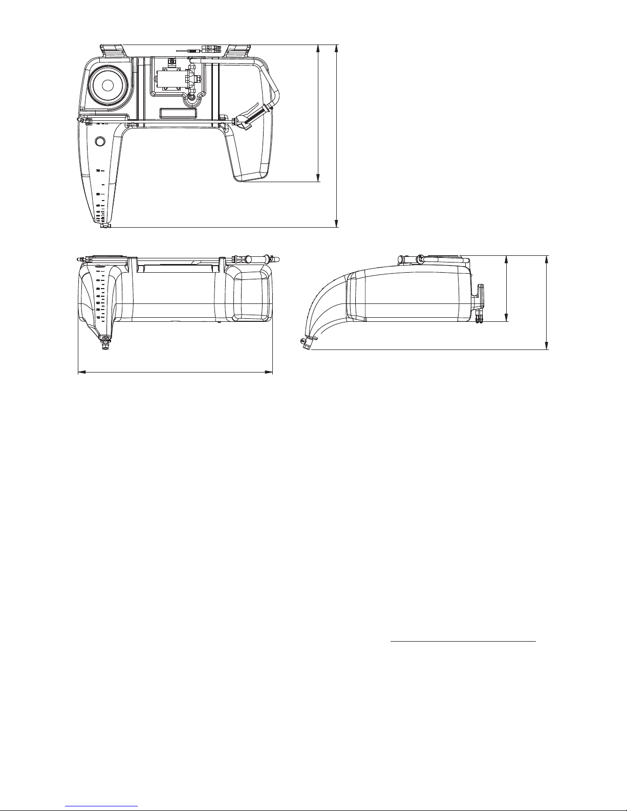
Dimensions
614mm
294mm
420mm
870mm
819mm
5
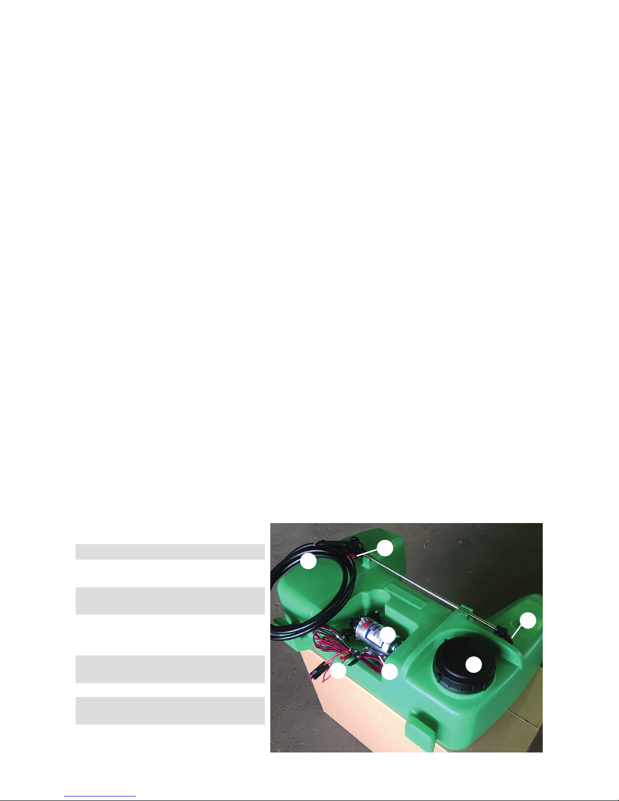
Key parts
Spray Application
After completing the lling process, you are
now ready to start spraying.
NOTE: It is the responsibility of the operator
to ensure that the chemical mix is suciently
agitated and that the conditions are right
to start spraying. Operators must wear the
appropriate PPE.
1. Switch “On” pump
2. Allow pump to build pressure
3. Engage the trigger on the spray lance to
start spraying
4. Adjust the nozzle pattern as required
by rotating the nozzle in the appropriate
direction
5. Use a consistent speed or swath pattern
to ensure even coverage of the target, or
adjust the method of application according
to your target
Agitation
Agitation should take place when lling or
through another method as deemed suitable
by the operator.
Flushing
The following information is provided as a
general guide for ushing your sprayer after a
spray application
For more specic information regarding
ushing, and decontamination, specic
to the products that you are applying, it is
recommended that you consult the chemical
label or your chemical supplier.
1. Turn pump o
2. Add a quantity of fresh water to main tank
and then drain.
3. Add a quantity of fresh water, and
decontaminating agents if required, to
main tank.
4. Turn on pump, and spray fresh water
through the lance / gun. This will ensure
that fresh water has circulated through the
pump and lance.
5. Drain remaining contents of fresh water.
The sprayer is now ready for storage.
Storage
If the sprayer is to be stored for a long period
of time without use, there are several tasks
that need to be performed.
1. Clean the sprayer thoroughly as described
under “ushing”
2. Store the sprayer out of direct sunlight and
where it will not be aected by frosts
3. Ensure that the main tank is empty
4. Protect hoses and electrical connections
Pos Part No Description Qty
1 GA5071300
75 Ltr Atv
tank with lid
1
2 GA5023400
Shuro 8000
pump
1
3 GA5022255
Wiring Loom
with in line
fuse
1
4 GA1100003
CT Trigger
gun CP500
1
5 38720-PPB Nozzle 12
6 HOS10P
10mm
Pressure hose
1
7 GA4523505
Serial Number
Plate
1
1
5
6
4
3
2
7
6
Problem Possible Cause Possible Remedy
Pump not priming Valves damaged
Restriction in suction line
Restriction in delivery line
Diaphragm damaged
Check, clean and/ or replace valve
kit
Check suction line
Check delivery line
Replace diaphragm
Pulsating liquid ow Pump switching on and o due
to pressure switch
Pump sucking air
Alter settings of the pressure switch
Alter the adjustable conejet nozzle
Restricted pump delivery
Check suction line
Pump pressure lower
than expected
Suction lter screen blocked
Restriction in suction line
Valves damaged
Diaphragm damaged
Pump sucking air
Insucient voltage
Clean screen
Check hoses, ttings and tank outlet
Check/or replace valve kit
Check/or replace diaphragm
Check suction line
Check power supply
Pump stopping and
starting when not in
use
Valves damaged
Insucient voltage
Damaged diaphragm
Check valves
Check power supply
Check/or replace diaphragm
Maintenance &
Troubleshooting
The troubleshooting information is provided
as a reference when your sprayer is not
functioning correctly. To ensure that you
receive the best possible service, it is
recommended that you exhaust all applicable
troubleshooting solutions shown prior to
calling your dealer for service advice.
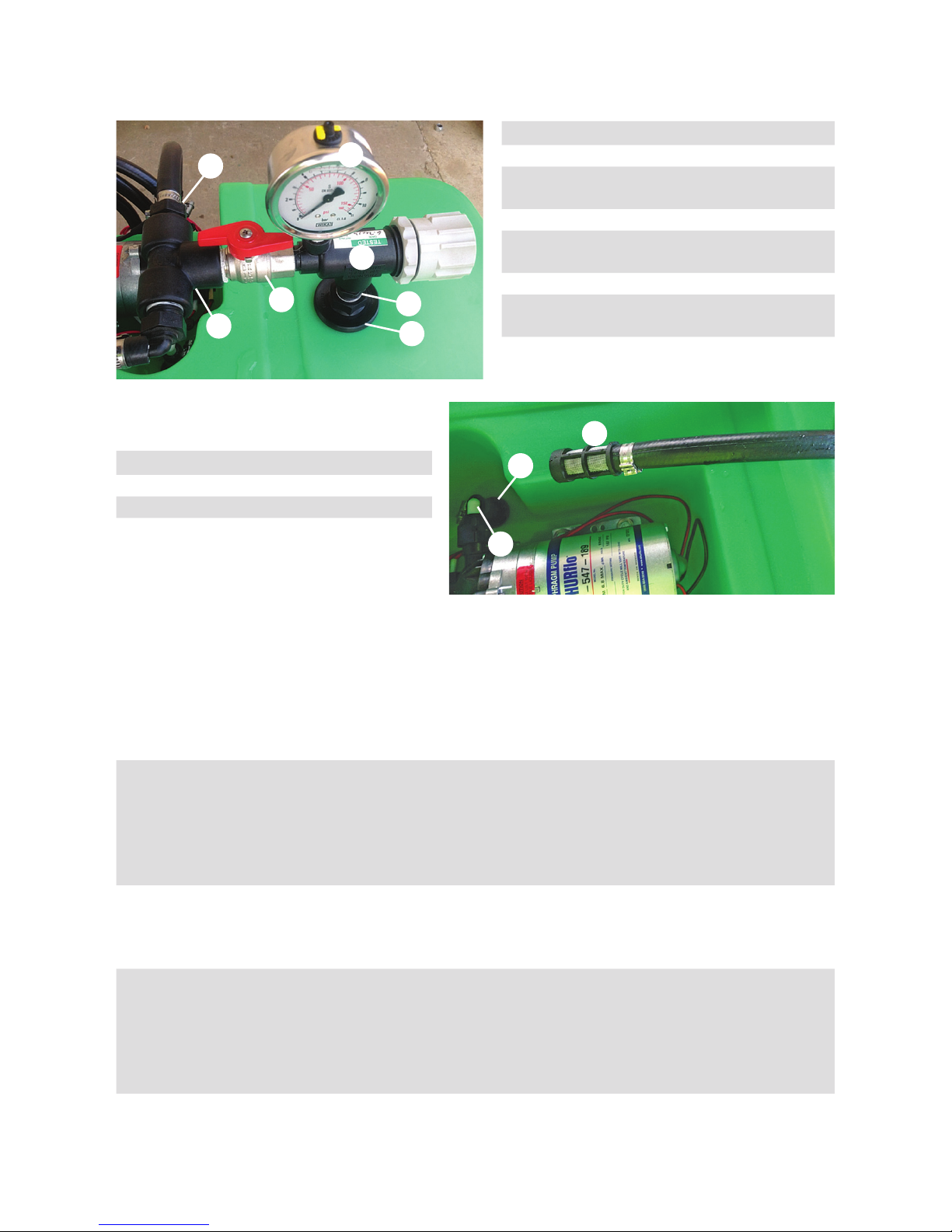
Suction lter - parts
Pos Part No Description Qty
1 305010 Filter 1
2 GA5012199 Grommet 1
3 GA5015187 Elbow ½” to ⅜” 1
*Fitted as option
Pressure regulator* - parts
Pos Part No Description Qty
1 23120-1/2-PP Regulator Valve 1
2 GA4948470
Small face 160
psi Gauge
1
3 TEE050 ½” Female Tee 1
4 HB050038
½” to ⅜” straight
hose tail
1
5 NIP050 ½” Nipple 1
6 GA5071400
½” through tank
tting
1
7 GA5020615
½” Male/Female
ball valve
1
1
1
5
6
4
3
3
2
7
2
7
Spraylance gun
The model CP500 spraylance is a lightweight
lance designed for use with low pressure
spraying systems. The Spraylance is made of
moulded polypropylene and stainless steel for
excellent chemical resistance and durability.
Features:
• 600mm spraylance
• Locking valve in open position for
continuous ow
Repair Kit for CP500 - GA5071440
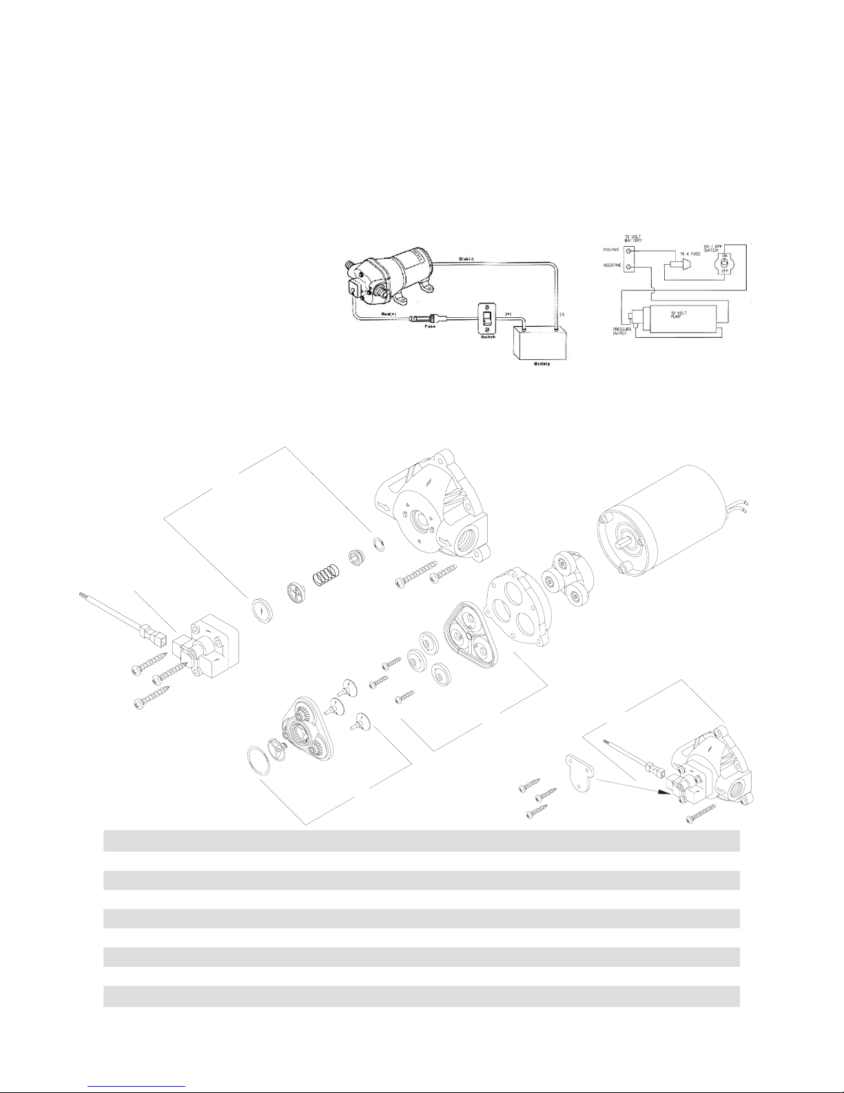
12v pump wiring
diagram
Important: Use 14 gauge stranded wire up to 6
metres from power source and 12 gauge up to
18 metres from power source.
Connect Red to Positive (+) terminal and Black
to Negative (-) terminal.
Service Kits
Kits are readily available to repair standard
8000 series pumps. Repair kits include
simple illustrated instructions allowing easy
installation. To insure that the correct kit is
received the model number and all name
plate data must be included with the order.
12v Shuro 8000
Pump 6.8 l/min 107 psi
1
7
3
2
5
Pos Part No Description Qty
1 Complete assembled pump head 1
2 GA5071545 Pressure switch assembly 1
3 GA5071560 Check valve components 1
4 Upper housing 1
5 GA5071550 Bypass valve and discharge valve assembly 1
6 Valve plate assembly 1
7 GA5071555 Diaphragm and piston components 1
8 Drive assembly 1
9 Motor assembly (less base plate) 1
8
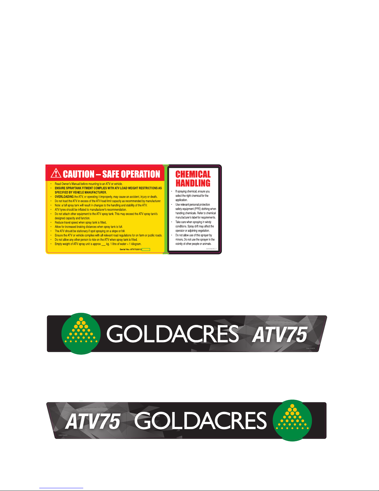
Safety Decals
Understanding safety decals and their purpose
assists in the safe operation of your sprayer.
Safety decals are there for your protection and
it is the responsibility of the owner operator
to replace damaged and/or missing safety
decals.
Regularly review safety decals with operators.
It is very important to ensure that all new
machine components and replacement parts
include current hazard identication decals.
Replacement safety decals can be ordered
from all Goldacres dealers.
GA8700409 ATV75 – Tank decal kit – Left & Right hand sides
GA5060617 Warning Label and Serial No.
GA8700410 ATV75 – Complete decal kit includes
Left & Right hand side tank decals and all warning label
 Loading...