

Goldacres ATV 200L, UV 400L, ATV 300L Operator's Manual

ATV 200 & 300L
UV 400L
Operator’s Manual

2
GENERAL INFORMATION & SPECS ����������3
Operation �������������������������������������������������4
Calibration �����������������������������������������������4
Spray Application �������������������������������������5
Storage �����������������������������������������������������5
Identification ��������������������������������������������6
Dimensions ����������������������������������������������6
MAINTENANCE & TROUBLESHOOTING
FOR 12V UNITS ��������������������������������������� 7
PARTS LIST ���������������������������������������������8
12v Pump Diagrams ������������������������������10
IOTA 20 PUMP���������������������������������11+12
Wheels & Tyres ��������������������������������������13
MANUAL FOLDING BOOMS �������������������14
30m manual hose reel ��������������������������� 16
AA30L GunJet ���������������������������������������17
Adjustable ConeJet Nozzle ��������������������18
IMPORTANT SAFETY MESSAGE FOR
OWNERS & OPERATORS ������������������������19
SAFETY �������������������������������������������������20
The Operator �����������������������������������������20
Safety Precautions ����������������������������������20
Safe use of chemicals �����������������������������21
Personal Protective Equipment (PPE) ����21
Safety Decals �����������������������������������������22
Identification �����������������������������������������22
TERMS & CONDITIONS ��������������������������24
Contact
Goldacres
1-3 Morang Crescent,
Mitchell Park Vic 3355
P: 03 5342 6399
F: 03 5342 6308
info@goldacres�com�au
Disclaimer
Any advice or recommendations given by Goldacres, Goldacres’ dealers, or employees is given in good faith and provided
based on the best information available to us� No liability or responsibility is accepted or implied as a result of any
information or advice tendered in this operating manual or by Goldacres its agents or employees� The end user accepts
all responsibility arising from that advice�
No part of this manual may be reproduced without written permission from Goldacres� All photographs and technical
information remain the property of Goldacres�

3
GENERAL INFORMATION
& SPECS
Tank:
All tanks are constructed from UV resistant
polyethylene� Polyethylene tanks have a very
high chemical resistance�
Due to the rotomoulding process, there can
be a variance in the overall dimensions of
the tank which in turn results in variations
to the tank capacity� For this reason, any
calibration markings should be used as a
guide only�
Filtration:
Filtration is a critical part of the sprayer’s
performance�
ATV200, 300 & UV400 are fitted with an
inline suction strainer� It is important that
the strainer is cleaned out regularly�
Pump:
The pump is critical to any sprayer
performance� Correct operation and
maintenance of the pump will ensure
the sprayer is able to perform to its
capabilities� Make sure the pump wires are
connected up to the correct terminals (red
to positive, black to negative)�
Always flush pump with clean water after
every use� Prolonged chemical contact can
severely damage valves, diaphragms and
seals�
Do not leave water in pump if sprayer is
to be left in a cold environment� The water
may freeze and cause damage to pump�
Empty pump of all water and cover the
pump to ensure this situation does not
arise� If this has not been done, and there
is a possibility there may be frozen water
in the pump, wait until any ice has thawed
before using the pump�
The 12 volt pumps are positive
displacement diaphragm pumps which
provide delivery upon demand�
They are self-priming and some models are
fitted with a pressure switch which senses
the outlet pressure of the pump� The
pressure switch turns the electrical power
off to the pump at a pre-determined high
pressure point�
As the outlet side of the pump is opened,
the pressure starts to drop and at a predetermined point (typically 40-75 psi)
contacts in the switch will lose causing the
pump to start automatically� The pump will
then pump until the pressure reaches the
shut-off pressure point�
CAUTION:
Do not adjust the pressure switch out so
that the pumping pressure exceeds the
maximum pressure for the pump�
If the flow demand is very low, the pump
may reach this high pressure point and
cause “cycling” (pump turns on and off
rapidly)�
This is not a problem unless the pump is
subject to continuous cycling within two
second intervals for long periods of time�
Altering the setting of the pressure switch,
or adjusting the agitation ball valve so that
there is some bypass back to the tank and
altering the adjustable conejet nozzle on
the gunjet will all remedy this situation,
depending on what is most suitable�
Chemical Induction:
Chemical should be put into the main tank
through the main tank lid� It is important to
ensure that chemical is thoroughly mixed
prior to spray application�
Nozzles:
As information regarding nozzles is specific
to those being used in your application,
no specific reference is made to nozzle
application rates or nozzle types in this
operator’s manual� Goldacres suggest the
use of a current nozzle selection catalogue
for reference to nozzle sizes, outputs, spray
patterns and general spraying information�
Goldacres recommends Lechler nozzles�

4
Operation
Connections
The following steps should be followed when
connecting to a power source:
1� Ensure that the battery is 12V DC
2� Connect the red connector to the
positive (+) terminal and the black
connector to the negative (-)terminal�
Filling
When filling the sprayer it is necessary to
use an external water source and wear the
appropriate PPE�
The following steps should be followed when
filling the tank:
1� Turn the pump off
2� Remove the tank lid
3� Add chemical as required� When
filling with water, after adding the
chemical, some agitation will take
place�
4� Use external water source to fill
main tank (Do not exceed the tank
capacity)
5� Replace the tank lid and ensure that it
is secure prior to switching on pump�
You are now ready to use the sprayer�
Calibration
All sprayers need to be calibrated and kept
in good condition� This will ensure that the
correct rate of chemical is applied to the
target�
Follow these steps to calibrate the sprayer:
1� Measure the spray width of the nozzle
on a dry surface (in metres)
2� Spray a test area at the intended
pressure and speed� Record distance
(in metres) covered in one minute
(minute)
3� Measure the nozzle output in litres
over one minute in a measuring jug
(l/min)
The spray volume can be calculated by the
formula below:
Nozzle output (l/min) x 10,000
Spray width (m) x speed (m/min)
Application rate (L/Ha) =

5
Spray Application
After completing the filling process, you are
now ready to start spraying�
NOTE: It is the responsibility of the
operator to ensure that the chemical mix is
sufficiently agitated and that the conditions
are right to start spraying� Operators must
wear the appropriate PPE�
1� Switch “On” pump
2� Allow pump to build pressure
3� Engage the trigger on the spray lance
to start spraying
4� Adjust the nozzle pattern as required
by rotating the nozzle in the
appropriate direction as required
5� Use a consistent speed or swath
pattern to ensure even coverage of
the target, or adjust the method of
application according to your target
Agitation
Agitation should take place when filling
or through another method as deemed
suitable by the operator�
Flushing
The following information is provided as a
general guide for flushing your sprayer after
a spray application
For more specific information regarding
flushing, and decontamination, specific
to the products that you are applying,
it is recommended that you consult the
chemical label or your chemical supplier�
1� Turn pump off
3� Add a quantity of fresh water to main
tank and then drain�
4� Add a quantity of fresh water, and
decontaminating agents if required,
to main tank�
5� Turn on pump, and spray fresh water
through the lance / gun� This will
ensure that fresh water has circulated
through the pump and lance�
6� Drain remaining contents of fresh
water� The sprayer is now ready for
storage�
Storage
If the sprayer is to be stored for a long
period of time without use, there are
several tasks that need to be performed�
1� Clean the sprayer thoroughly as
described under “flushing”
2� Store the sprayer out of direct
sunlight and where it will not be
affected by frosts
3� Ensure that the main tank is empty
4� Protect hoses and electrical
connections

6
Identification
When ordering parts or requesting service
information for your sprayer it is important
to quote the serial number of your machine,
and the purchase date, in order to receive
accurate information� The location of the
serial number is shown in the picture� This
serial number is stamped into the serial
number plate�
Dimensions
Please note: Dimensions are approximate only and may be subject to change without
notice�
Model Width
mm
LengthmmHeightmmDry
Weight
200 Lt ATV with 12V pump & 3 Mt al� boom 1262 2213 1000 110 kg
300 Lt ATV with 12V pump & 4 Mt steel/
aluminium crossover boom
1262 2213 1000 115 kg
300 Lt ATV with engine driven pump & 4 Mt
steel/aluminium crossover boom
1262 2213 1000 120 kg
400 Lt UV with engine driven pump & 4 Mt
steel/aluminium crossover boom
1562 2378 1320 130 kg

7
Problem Possible Cause Possible Remedy
Pump not priming
Valves damaged
Restriction in suction line
Restriction in delivery line
Diaphragm damaged
Check, clean and/ or replace
valve kit
Check suction line
Check delivery line
Replace diaphragm
Pulsating liquid
flow
Pump switching on and off due
to pressure switch
Pump sucking air
Alter settings of the pressure
switch
Alter the adjustable conejet
nozzle
Restricted pump delivery
Check suction line
Pump pressure
lower than expected
Suction filter screen blocked
Restriction in suction line
Valves damaged
Diaphragm damaged
Pump sucking air
Insufficient voltage
Clean screen
Check hoses, fittings and tank
outlet
Check/or replace valve kit
Check/or replace diaphragm
Check suction line
Check power supply
Pump stopping and
starting when not
in use
Valves damaged
Insufficient voltage
Damaged diaphragm
Check valves
Check power supply
Check/or replace diaphragm
MAINTENANCE &
TROUBLESHOOTING FOR
12V UNITS
The troubleshooting information is provided
as a reference when your sprayer is not
functioning correctly� To ensure that
you receive the best possible service,
it is recommended that you exhaust all
applicable troubleshooting solutions shown
prior to calling your dealer for service
advice�
8
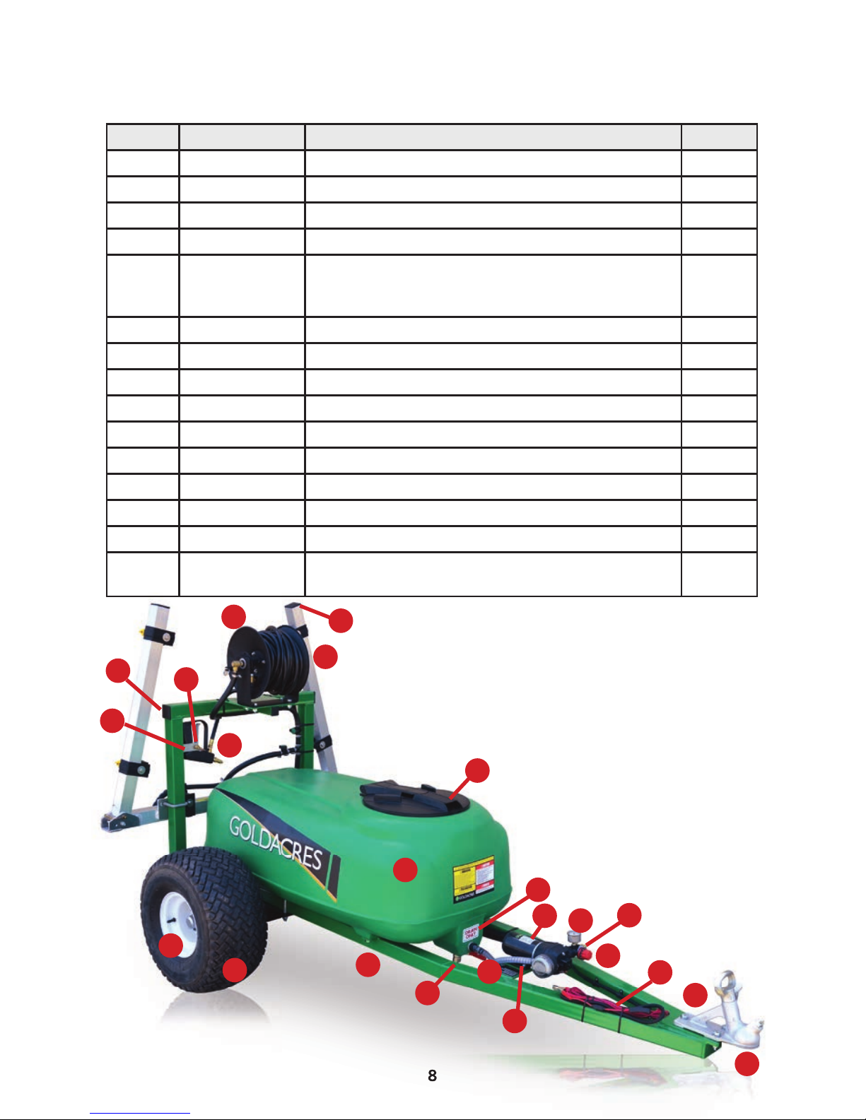
PARTS LIST
ATV200/3
GA4905995 ATV300/4 GA4905975
8
Position Part No Description Quantity
1 GA4515600 ATV tank support mount 2
2 GA5023670 Mini hub & stub ass 2
3 GA5023665 Tyre nobby (22x11-8 x 6 ply) & 4 stud mini rim 2
4 300120 Filter, basket type, diam 305 x 245 deep 1
5 GA8500000
GA5023660
GA5023750
Tank, 200L, ATV low profile, green
Tank, 300L, ATV low profile, green
Tank, 400L, UV low profile, green
1
6 GA4522140 Tow ball mounting plate 1
7 GA5049100 Trailer coupling 50mm bolt on 1
8 GA5014955 Serial ID plate 1
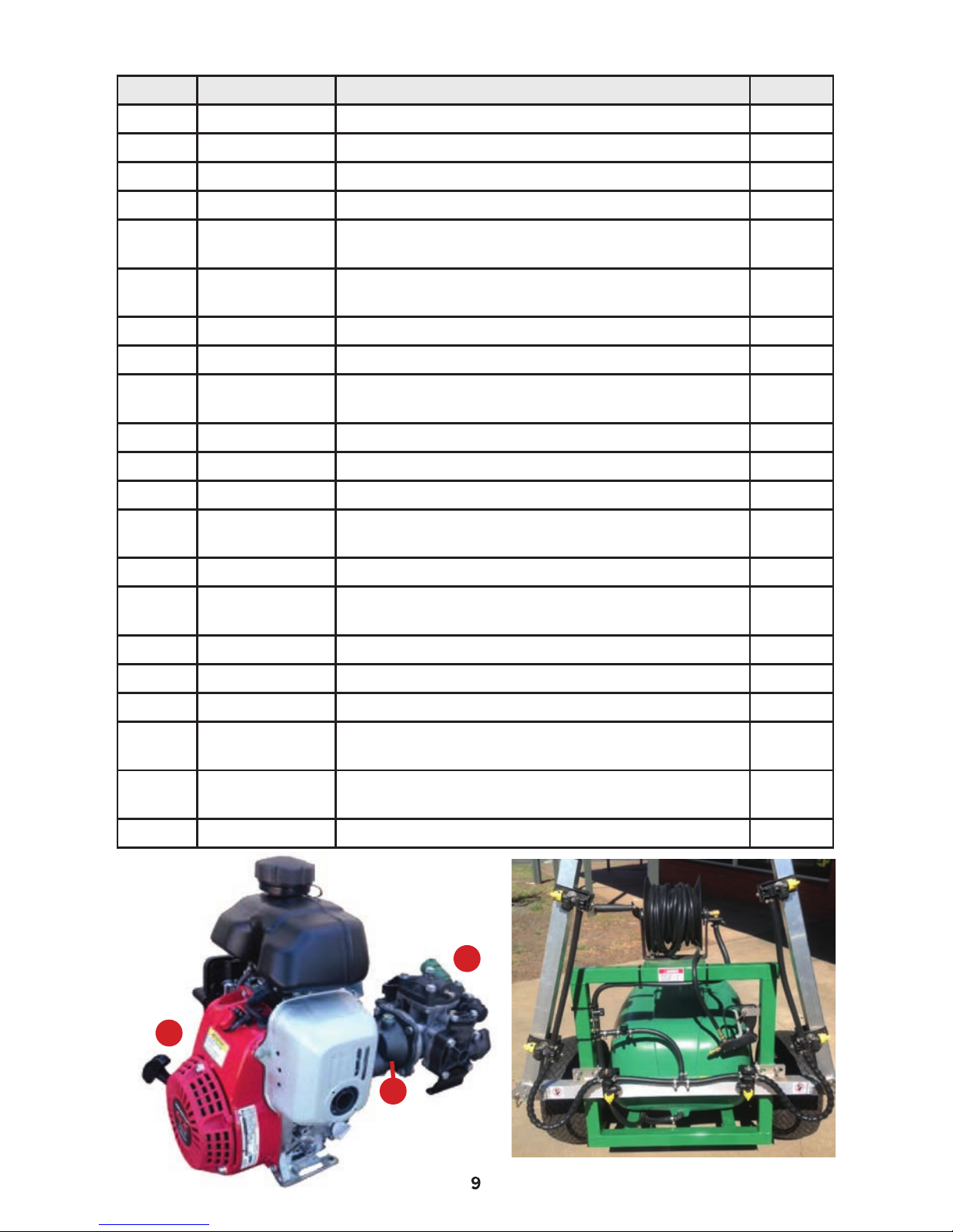
9 GA5023895 GX100 Honda 1
10 5091D9 Udor 6:1 reduction gearbox suit Honda 3 hp 1
11 Iota20 Iota 20—20 l/min diaphragm pump 1
12 GA5012161 Narva split tubing 7mm (not shown) 0�5
13 GA5051245 Plastic P clamp 7�9mm (not shown) 0�004
14 GA5012049 Narva joiner red 2�5-3mm wire (not shown) 0�002
15 006530 Hose barb, elbow, 90 degree, 1/2 fly end x 13mm
hose, brass, Arag
1
1
31
2
32
3
33
4
34
5
15
25
35
6
16
26
36
7
17
27
8
18
19
20
9
9
Position Part No Description Quantity
16 GA5066085 15 mtr hose reel manual, 3/8” 1
17 GA5053250 Pressure gauge, small face, 0-400kPa 1
18 GA4900546 Gunjet, AA30, adjustable nozzle with fittings 1
19 GA5015971 Sticker Drain Only 1
20 GA5020620 Valve, ball, 12mm thread male/female inlet/
outlet, lever handle, SS
1
21 HB050-90 Hose barb, Elbow, 90 degree, 1/2 male thread x
1/2 hose, Banjo (not shown)
3
22 HOS12SIGHT Hose, clear, 12mm sight tube (not shown) 4
23 GA5007231 Hose clamp, cobra type, 1/2 (not shown) 2
24 HB075/050-90 Hose barb, elbow, 90 degree, 3/4 male thread x
1/2 hose, Banjo (not shown)
1
25 GA4534635 Bracket nozzle suit small booms 1
26 GA5013003 Pipe linch pin, 8OD x 60 long 1
27 GA4900093 Boom, 3m, with plumbing, 6 nozzle, manual fold 1
28 HOS13P Hose, pressure, 12mm, black, 250psi boom
pumps (not shown)
4�5
29 GA5000469 Hose clamp 1/2, SS (not shown) 13
30 GA5020355 Hose barb, brass, elbow, 90 degree, 1/2 male
thread x 1/4 hose (not shown)
1
31 GA5003783 50 x 50mm square tube insert black 4
32 GA5002911 35 x 35mm square tube insert black 1
33 GA5066540 Pump, electric 12V, 13�5 L/min 1
34 GA5022255 Electrical harness, 17 AWG wire in line fuse &
alligator clips
1
35 9620522 Valve, pressure regulating, polypropylene, 20 L/
min Arag
1
36 HOS12WSIGHT Hose, 12mm, clear, wire reinforced 0�5
11
9
10
 Loading...