

Gold JTM27A82A Service Manual
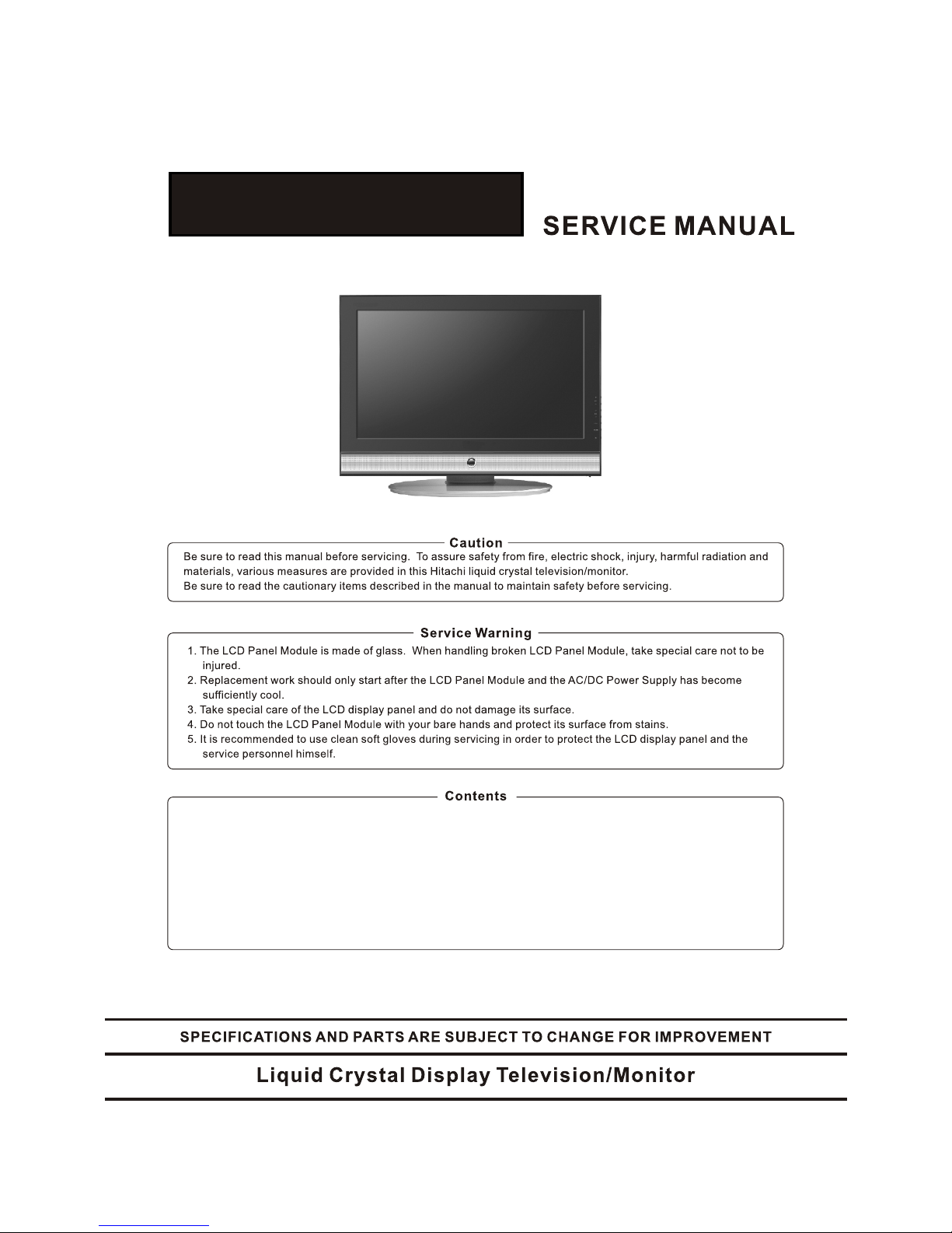
JTM27A82A
.Safety Notice 2 . Printed Circuit Board 24
.Display Modes . Block Diagram 32
.Specifications 4 .Wiring Diagram 33
.Location and Function of
Controls 5 . Expl od ed V ie w an d Me ch an ic al P ar ts 34
.Installation and connecting 8 . Ic s fu nc ti on description 3
6
. P ar ts L is t( F or R ef er en ce O nl y) 47
. Schemtic Diagrams 9
2
2
COMPONENT VIDEO (YPbPr) INPUT
720p/60
720 44.96
59.94/60.00
576i 576
15.63
50.00
480i 480
15.73
59.94/60.00
576p
576
31.26
50.00
480p
480
31.47
59.94/60.00
1080i/50
1080
28.13
50.00
1080i/60
1080
33.75
59.94/60.00
Mode Resolution
Horizontal Frequency (K Hz) Vertical Frequency (Hz)
Display Modes
3
RGB INPUT
1024x768
38.36(N) 60.00(N)
65.00
640x480
31.47 (N) 60.00 (N)
25.18
DOS
800x600
37.88 (P) 60.32(P)
40.00
VESA
VESA
1280X768
64.00(P) 60.00(P)
108.00
VESA
Resolution
Horizontal
Frequency (KHz)
Pixel
Frequency (MHz)
Comment
Vertical
Frequency (Hz)
● Modes, which are not listed in the above table, may not be supported. For an optimal picture is
recommended to choose a mode listed in the table.
● The incoming display modes compatible with WINDOWS as shown in the table above.
● Sometimes, the image may be disrupted due to the frequency standard from the VGA card.
However, this is not an error. You may improve this situation by activating the automatic
adjustment or by manually changing the phase and the clock settings in the menu.
● To extend the service life of the product, we recommend that you use your computer’s power
management function.
1080i/60
1920X1080
33.75
60.00
60.00
VGA
640X480
31.47
59.94
576p
720X576
31.25
50.00
50.00
50.00
1080i/50
1920X1080
28.13
Mode Resolution
Horizontal Frequency (K Hz) Vertical Frequency (Hz)
720p/50
1280X720
1280X720
37.50
720p/60
45.00
HDMI INPUT

Specifications
4
LCD Panel
Size
Display size
Pixel Pitch
View Angle
Frequency
Horizontal
Vertical
Display color
Display Resolution
Maximum Mode
Optimum Mode
Input Source
Sync.
Video Signal
TV
Color System
Sound System
Video
Color System
Video Format
Power Supply
Input
RGB Signal
Power Consumption
Working
Standby
Environmental Considerations
Operating Temperature
Operating Humidity
Audio Characteristics
Dimension ( WXDXH) mm
Weight (Kg)
Net Weight
Audio Input
Frequency
Response
Audio Input (PC)
Note:
● Design and specifications are subject to change without notice.
● Weight and dimensions shown are approximate values only.
Gross Weight
Without Stand
With Stand
H/V separate, TTL, P. or N.
1Vp-p @ 75 ohm
0.7 Vp-p @ 75 ohm
PAL/SECAM
BG, DK, I, L
AC 100~240V, 50/60Hz
10℃ ~ 40 ℃(50°F ~ 104°F)
10% ~ 80%
RCA Jack (L, R), 0.5Vrms (-9dB)
RF: 100Hz~12KHz (at ± 3dB)
A/V: 100Hz~13KHz (at ± 3dB)
RCA Jack (L, R), 0.5Vrms (-9dB)
30~80KHz
56~60Hz
16.7M colors
PAL/SECAM/NTSC
CVBS, S-VHS, RGB
140W
< 3W
11.0
14.0
27" Diagonal
566.40(H) X 339.84 (V) mm
0.4425(H) X 0.4425 (V) mm
176 °/176°(H/V)
1280 X 1024 @ 60Hz
1280 X 768 @ 60Hz
681.2X93.4X474.0
681.2X245.6X527.9
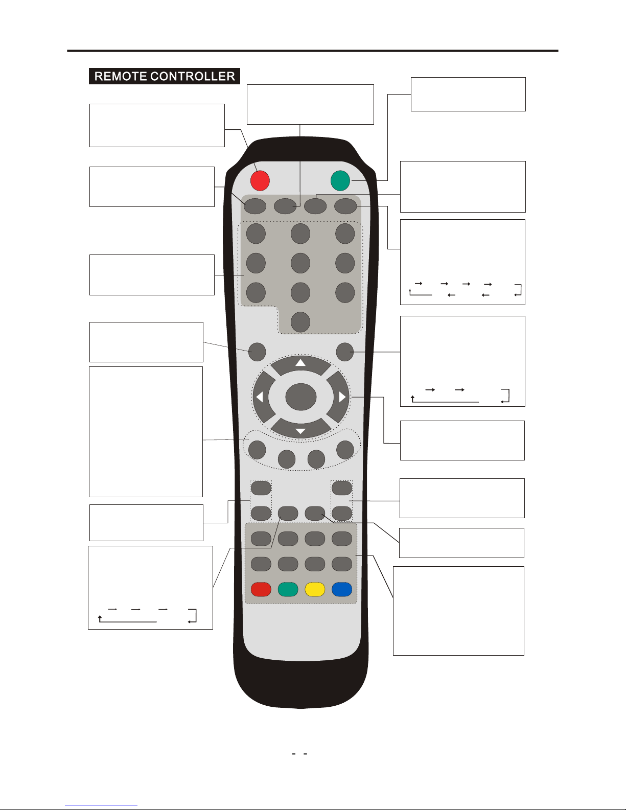
Location and Function of Controls
5
ME NU
PICTURE
TV
VI DE O PC
COMP
SLEEP
WIDE
IN DE XHO LDMI XT EX T
SUBPAGE
REVEAL
SI ZE
CANCEL
CY AN
YELLOW
GREEN
RE D
ENTER
STANDBY
MUTE
DISPLAY
RETURN
MT S SOUND
1 2
3
4
5
6
7
8 9
0
+
-
PROGRAM SELECT
Press these buttons to select
a TV program directly.
p q t u and ENTER
select menu items and adjust
menu values.
VOL+/VOL-
RETURN
Return to previously selected
program number.
MUTE
Switch the sound on or off.
STANDBY
Switch on the LCD TV when at
standby mode or vice versa.
DISPLAY
Display the source and channel
information
4:3 16:9
DISPLAY MODE
You may recall the display mode
by pressing this button. Each
time pressed, display mode is
changed in following sequence.
MENU SELECT
Enter or exit from the OSD
menu.
INPUT SOURCE SELECT
TV button
Select the TV mode.
VIDEO button
Select a mode among AV,
S-Video and SCART.
PC button
Select the VGA and HDMI
mode.
COMP button
Select the YPbPr mode.
Press to increase or decrease
volume.
MULTI-SOUND SELECT
Switch between NICAM Stereo,
NICAM DUAL1,NICAM DUAL2,
NICAM Mono or Mono.
EQ MODE
You may recall the equalizer
mode by pressing this button.
Each time pressed, EQ mode is
changed in following sequence.
Off R ock Pop Live
PICTURE MODE
You may recall the picture
mode by pressing this button.
Each time pressed, picture
mode is changed in following
sequence:
Sport Vivid Hi-Bright
User
Soft
Dance
Techno
Classic
+
-
VOL
CH
CH+/CH-
Select channel in ascending or
descending order.
TELETEXT AND PROGRAM
EDIT
These buttons are used for
certain models with Teletext
functions. For further details,
refer to “TELETEXT FUNCTION”
section.
SLEEP
To select the sleep time.
Note:
the prompt message “Invalid Key” will appear if you press a button for a function that is not
available.
Full
Auto
Normal
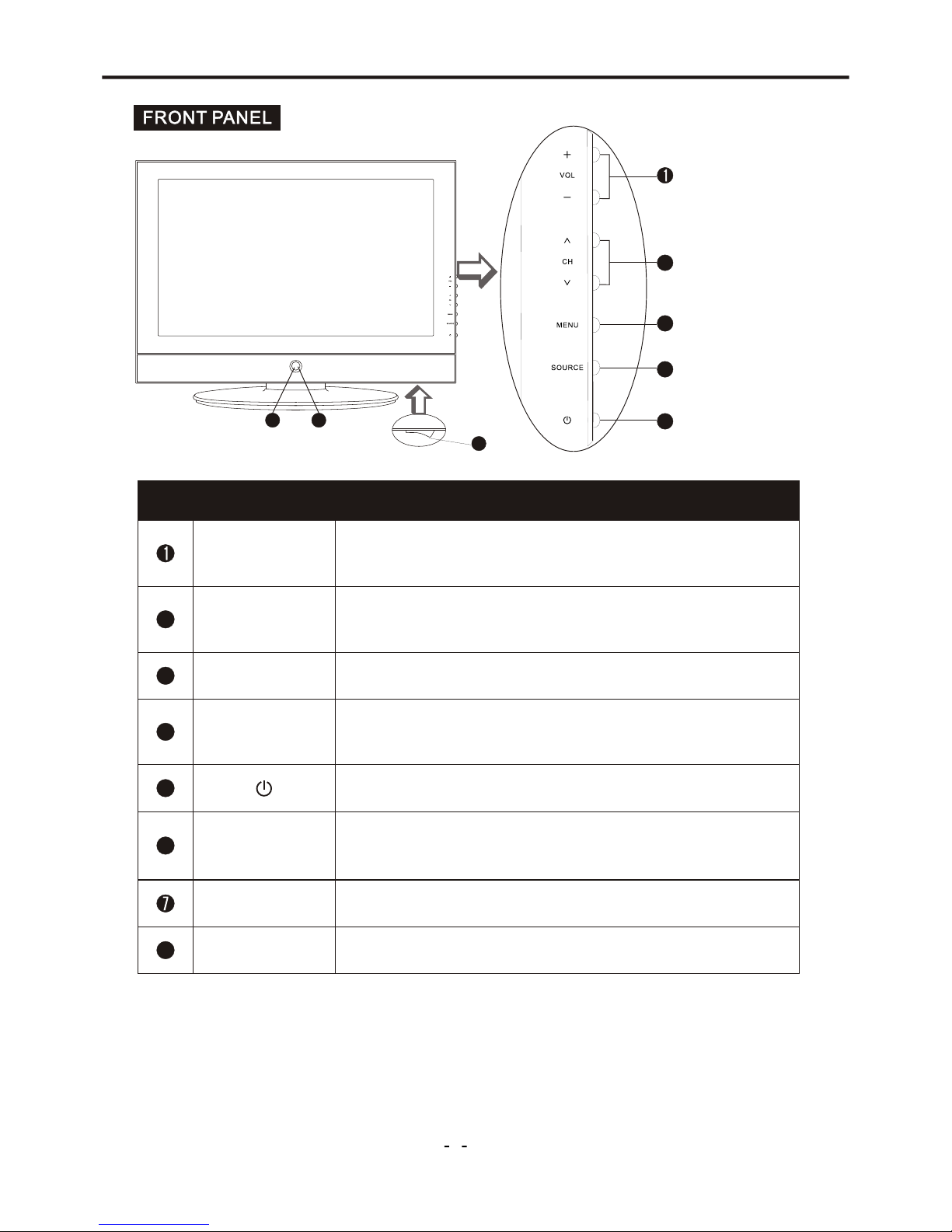
Location and Function of Controls
6
Button NameButton Name
DescriptionDescription
VOL +/-
Power Indicator
Remote Sensor
Increase or decrease the volume.
Adjust the values of the selected menu item in the OSD menu.
Enter or exit from the menu.
Switch on the LCD TV when at standby mode or vice versa.
Illuminates red in standby mode.
Illuminates green when the LCD TV is switched on.
5
4
3
2
6
ItemItem
When you are watching the TV program, press these buttons
to select channel in ascending or descending order.
Select the upper or lower menu item in the OSD menu.
Select input signal between TV, Video, S-Video, YPbPr, Audio,
SCART, PC and HDMI.
SOURCE
MENU
Infrared sensor for the remote control.
5
4
3
2
6 7
CHÚ/ÙCHÚ Ù
8
Main Power Switch
Switch on/off the LCD TV.
8
Note:
If there is no signal input from VGA/HDMI for 1 minute, or no signal input from other video source
(the blue background should be set to On) for over 15 minutes, the LCD TV will switch to standby
automatically. The power indicator will light up in red.
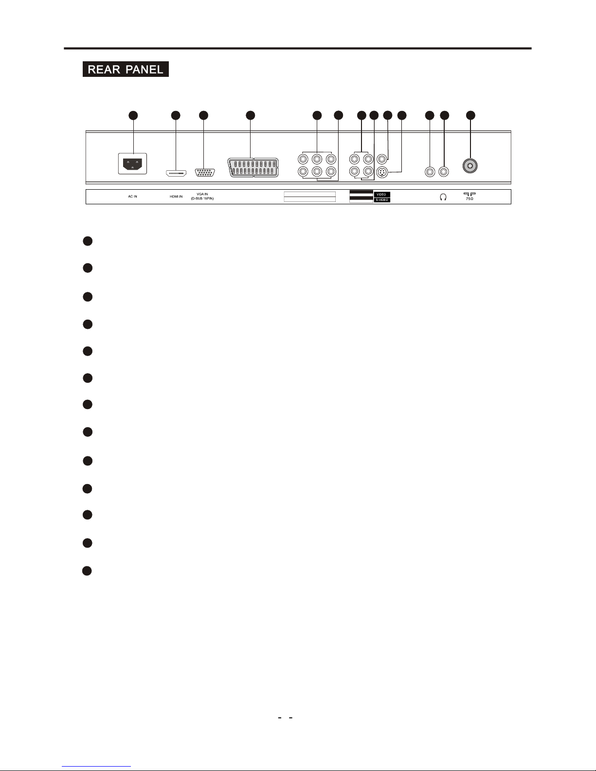
Installation and Connecting
7
2
AC Input Socket
3
HDMI Input Connector
4
VGA Input Terminal
S-VIDEO Terminal
6
Video Input Terminal
7
8
10
RF Input Socket
9
SCART Connector
11
12
Headphone Output Terminal
YPbPr-Audio Input Terminals
LINE IN (VGA Audio) Terminal
13
YPbPr Component Video Input Terminals
AV Out Terminals
Video-Audio Input Terminals
1
5
1
2
3
7
8
6
11
4
10
SCART
5
9
LINE IN
13
AV OUT VID EO L R
Y Pb Pr
12
L R
VIDEO -AUDI O IN
YPbPr -AUDI O IN
L R
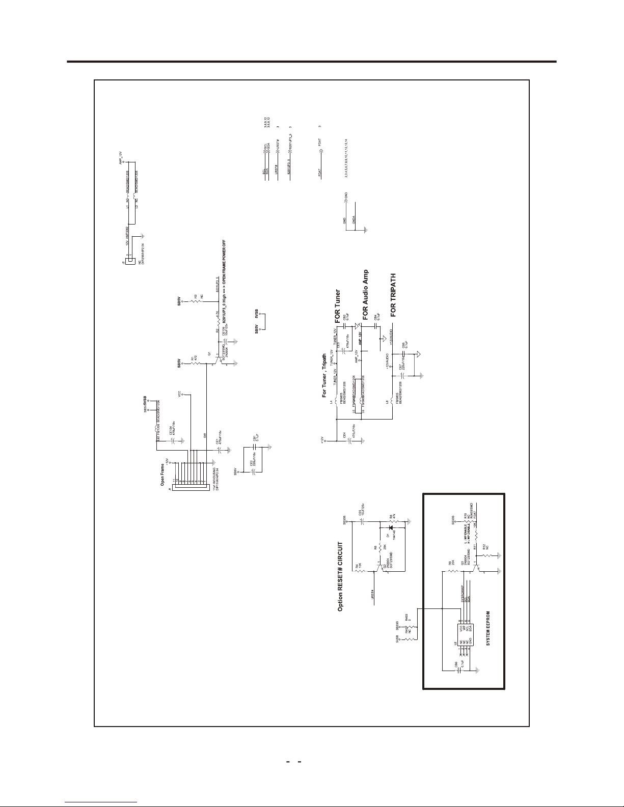
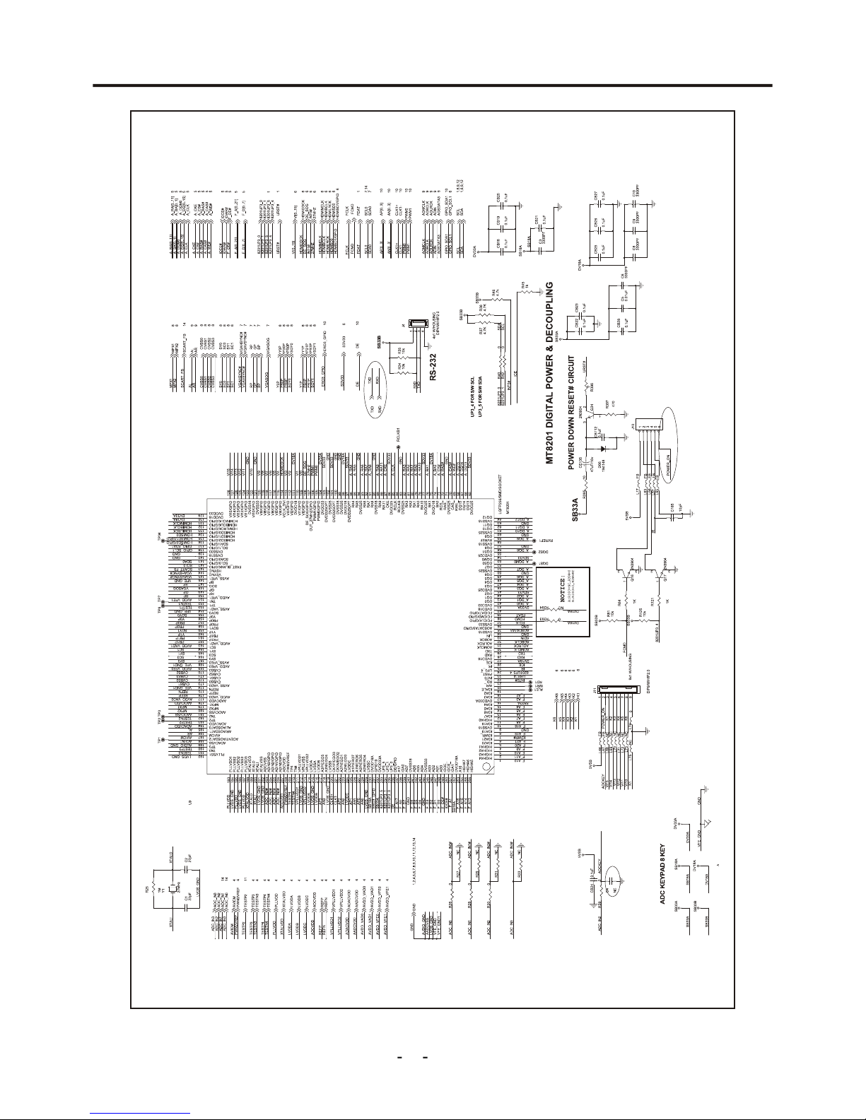
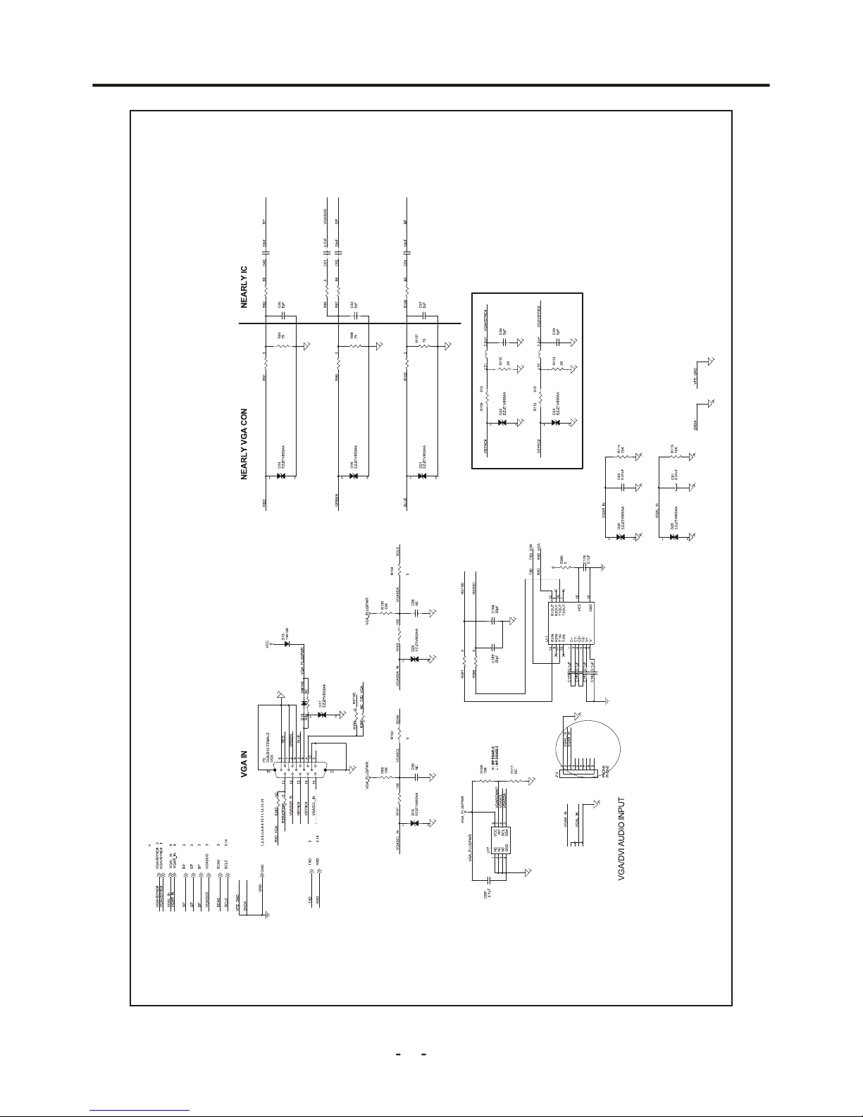
Schemtic Diagrams
8
Figure1- 1.1DRIVE Schematic Circuit
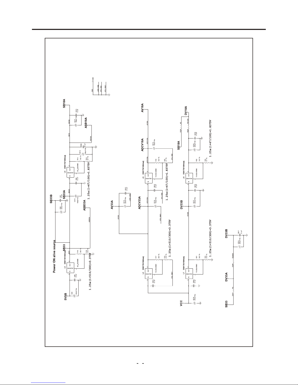
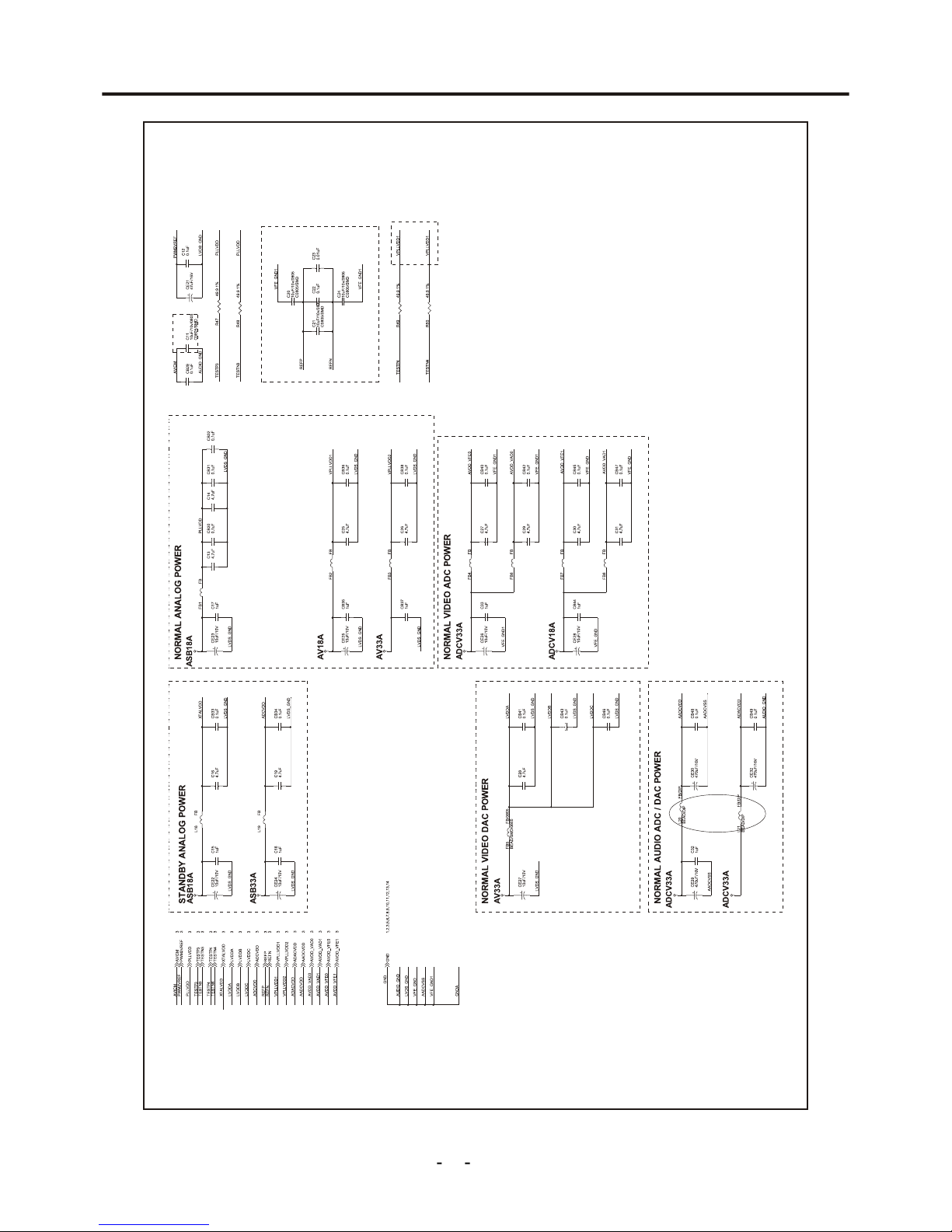
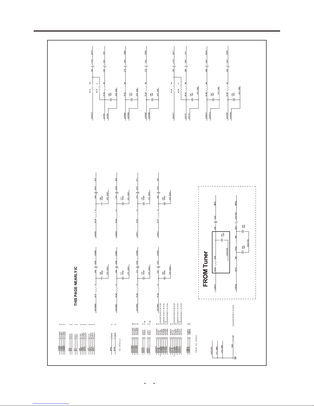
Schemtic Diagrams
9
Figure1- 1.2DRIVE Schematic Circuit
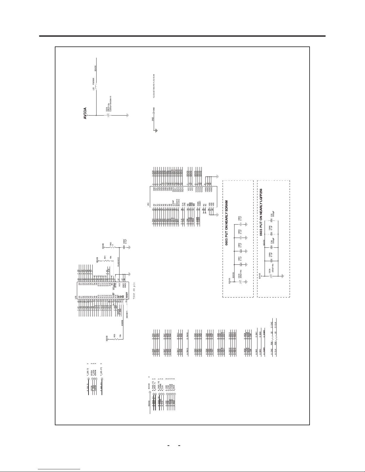
Schemtic Diagrams
10
Figure1- 1.3 DRIVE Schematic Circuit
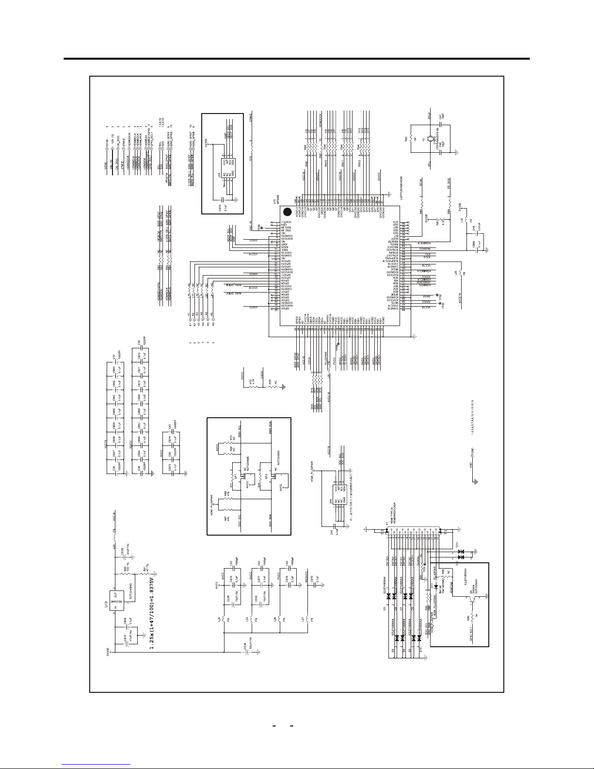
Schemtic Diagrams
11
Figure1- 1.4 DRIVE Schematic Circuit
Schemtic Diagrams
12
Figure1- 1.5 DRIVE Schematic Circuit
Schemtic Diagrams
13
Figure1- 1.6 DRIVE Schematic Circuit
Schemtic Diagrams
14
Figure1- 1.7 DRIVE Schematic Circuit
Schemtic Diagrams
15
Figure1- 1.8 DRIVE Schematic Circuit
 Loading...