

GoinGreen G-wiz Owner's Manual

automatic electric vehicle
OWNERS MANUAL
For Service and assistance contact
Email: service@goingreen.co.uk web: www.goingreen.co.uk
Ph: 0208 843 0846 (8 a.m. to 6 p.m., Monday- Friday)
GoinGreen, Green Station, 201 Beaconsfield Road,
Southall, Middlesex, UB1 1DA
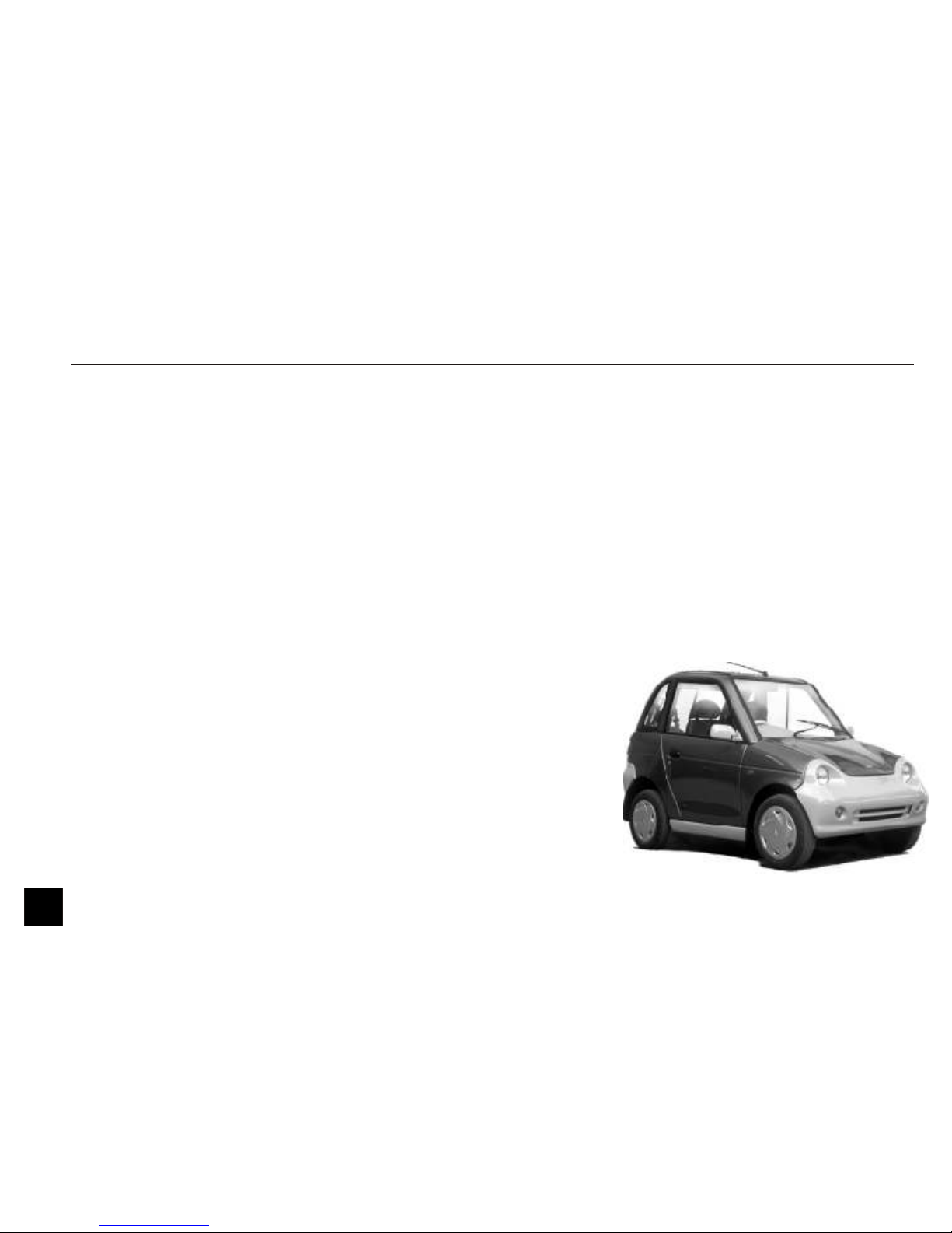
Congratulations ! You have made a wise decision by choosing to own this
automatic electric vehicle!
G-Wiz is a whole new concept in city mobility, a step forward towards a pollution free
environment – something our future generations will thank us for. And with it,
G-Wiz will provide you with years of hassle free ownership.
Please read this Owner’s Manual carefully. It has been structured to provide you with
all information you need on the operation and maintenance of your car. Please keep it
safe, as it will be of helpful should you require any assistance.
We also encourage you to carefully read the Warranty terms and conditions. It will
help you understand the warranty coverage and responsibilities for ensuring warranty
protection for your car.
Your car maintenance schedule is also provided in this manual. Following the schedule
will help keep your driving hassle free and also preserve your investment.
Everyone here at Goingreen is dedicated to ensure your driving satisfaction. Please
email us at service@goingreen.co.uk should you have any questions or concerns at
anytime.
We wish you the joy of commuting without polluting!
Foreword
1
Important
Please read this manual and follow the
instructions carefully.
Signal words CAUTION and NOTE
have special meanings.
CAUTION indicates a potentially
hazardous situation which, if not
avoided, may result in injury or
property damage.
CAUTION
NOTE indicates information to
assist maintenance and instructions.
NOTE
Obey all safety messages that follow
these symbols.
: This asterisk in the manual
signifies that an item is an optional
extra.
All information, illustrations and
specifications in this Owner’s Manual
were in effect at the time of printing.
GOINGREEN in the course of product
development reserves the right to
discontinue or change specifications or
design at any time without notice and
without incurring any obligation
whatsoever.
2

Main Controls ....................................................
1.0 Instrument Cluster & Controls ...........................
2.0 Climate Control Seats.........................................
3.0 Charging Your G-Wiz .........................................
4.0 Driving Your G-Wiz ...........................................
5.0 Tyres ..................................................................
6.0 Do’s and Don’ts .................................................
7.0 Troubleshooting .................................................
8.0 Maintenance .......................................................
9.0 Service Schedule .................................................
10.0 G-Wiz’s Safety Features ......................................
11.0 Key Technologies ...............................................
12.0 Power Pack ........................................................
13.0 Technical Specifications .....................................
14.0 Vehicle identification numbers ............................
15.0 Index .................................................................
4
5&6
33
35
43
49
53
59
65
77
81
83
87
91
95
97
Contents
3
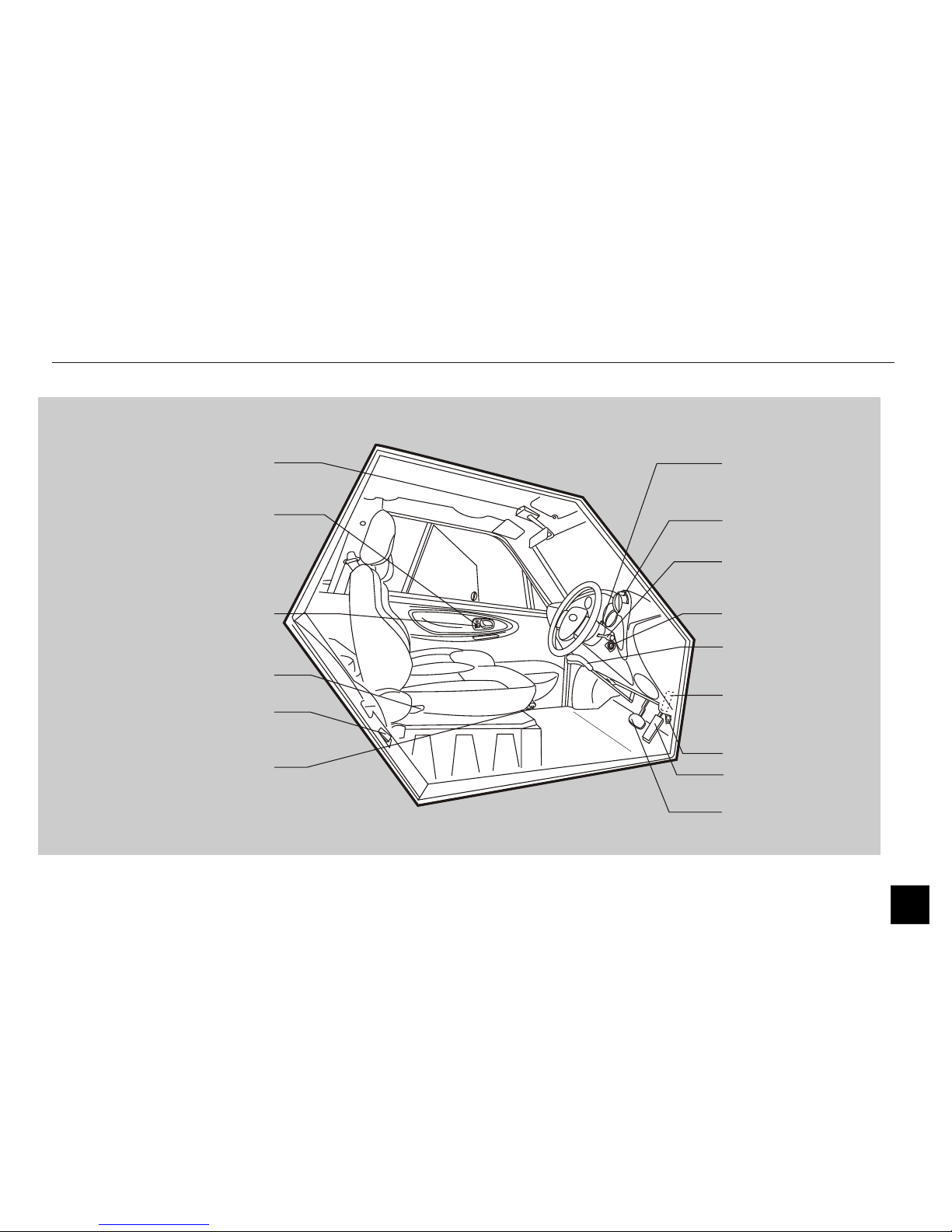
Main Controls
Main Controls
ROOF LIGHT SWITCH
DOOR LOCK
DOOR OPENING LEVER
SEAT-RECLINING LEVER
HATCH OPENING LEVER
SEAT-SLIDING LEVER
HAZARD WARNING
SWITCH
CONTROL KNOB
HEAD LIGHTS +
TURN SIGNAL LEVER
START-UP KEY SWITCH
PARKING BRAKE
FUSE BOX
HOOD OPENING LEVER
ACCELERATOR PEDAL
BRAKE PEDAL
4
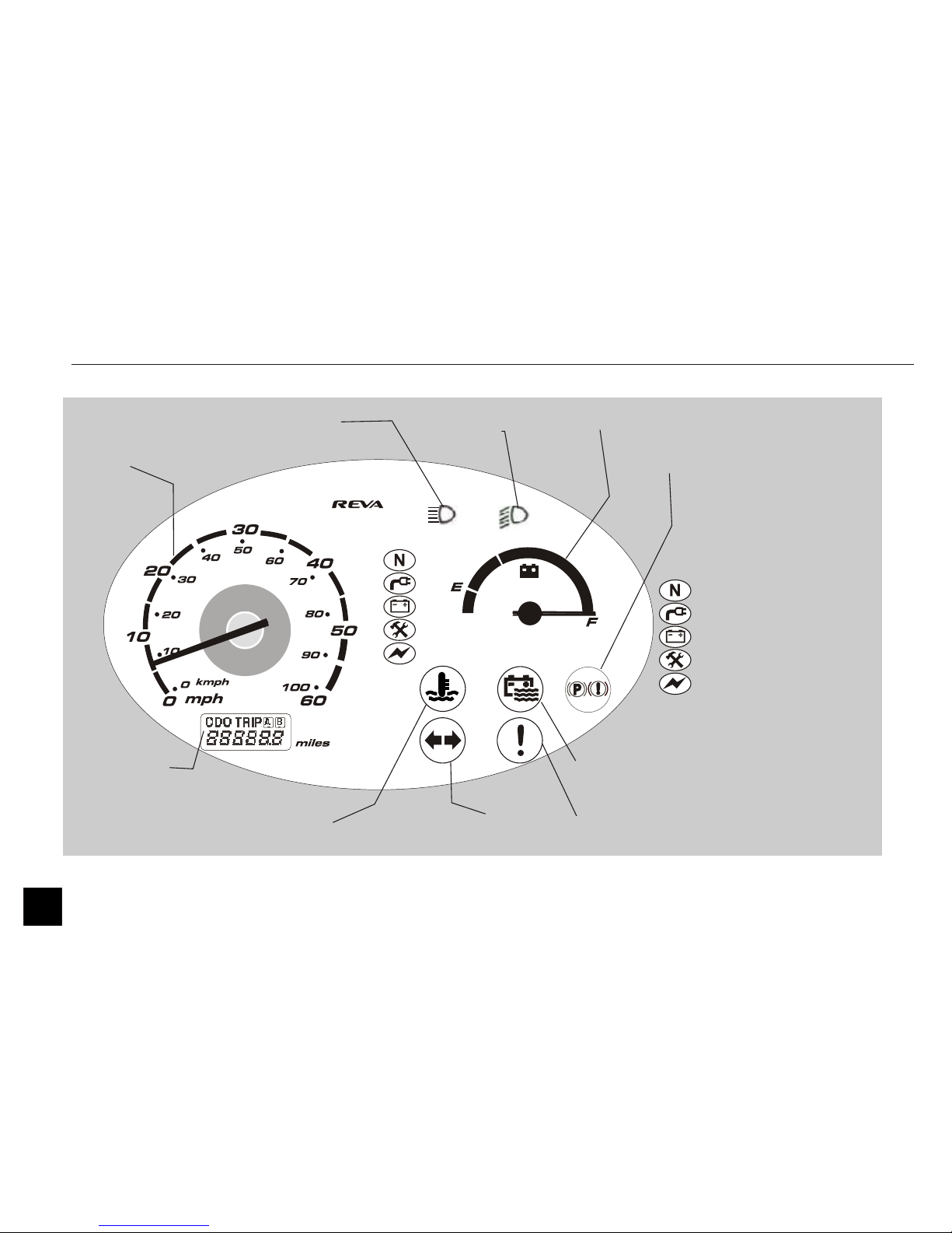
Instrument Cluster
Instrument Cluster
5
= NEUTRAL (drive sequence)
= CHARGING
= LOW BATTERY
= SERVICE
= (GREEN) REGEN (RED) EXTRA
POWER USAGE (Dual
colored LED)
TURN SIGNALS
LOW BEAM LIGHT
POWER GAUGE
PARKING BRAKE / LOW
BRAKE FLUID LIGHT
BATTERY LOW WATER
LIGHT
HIGH BEAM LIGHT
TEMPERATURE LIGHT
SPEEDOMETER
ODOMETER /
TRIP METER
ENCODER FAULT
1.1 Indicator Lights ....................................................
1.2 Gauges..................................................................
1.3 Steering Wheel Controls........................................
1.4 Control Knob .......................................................
1.5 Climate Control System.........................................
1.6 Keys / Key switches...............................................
1.7 Door Locks ..........................................................
1.8 Seat Adjustment....................................................
1.9 Hood ....................................................................
1.10 Rear Hatch ...........................................................
1.11 Parking Brake .......................................................
1.12 Roof Lights ..........................................................
1.13 Compartments.......................................................
1.14 Mirrors, Audio system, sunvisor, 12V socket..........
7
12
13
15
16
20
21
24
28
29
30
30
31
32
6
1.1 Indicator Lights
When the key is turned ON or OFF,
some of the lights of the instrument
panel cluster glow for short time.
This is part of the car’s self test
program.
In case you notice any change in this
behavior during usage, please
contact Goingreen on
service@goingreen.co.uk
NOTE
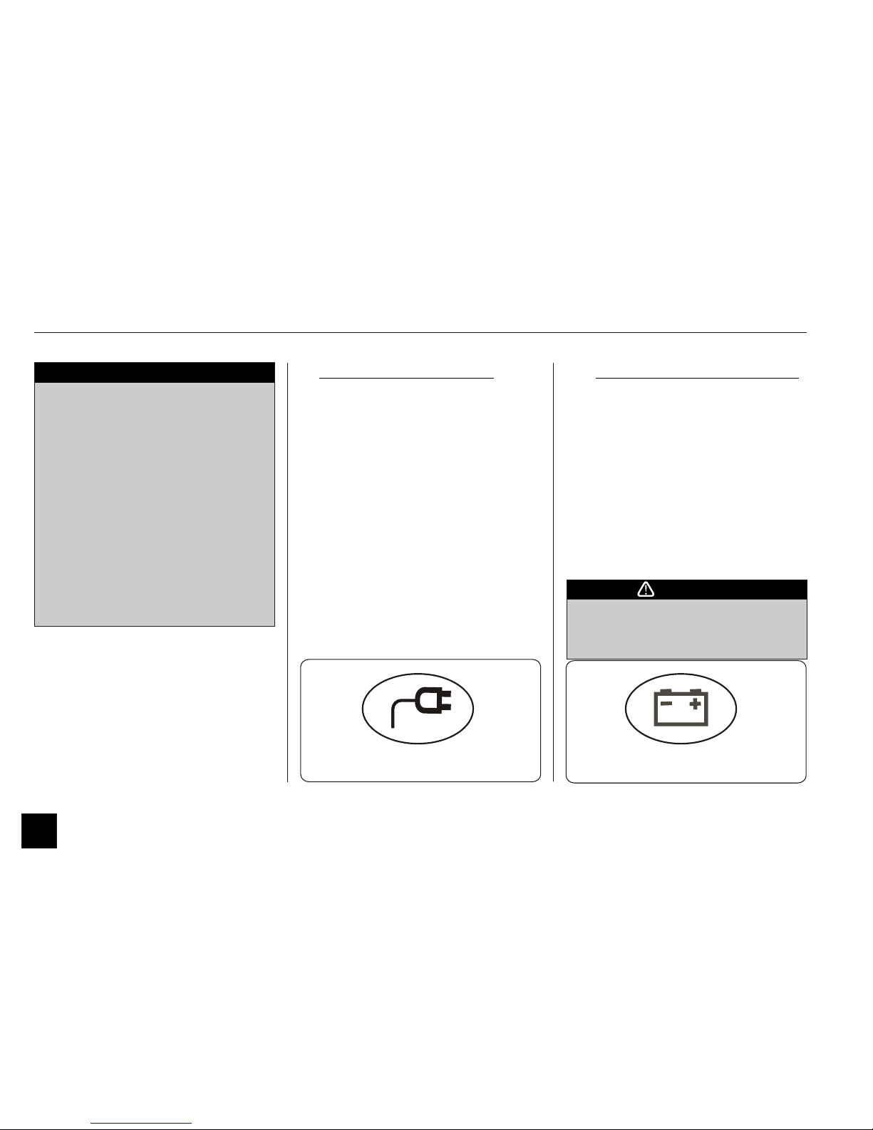
I. CHARGE LIGHT (Green)
This light should come on and flash
green when your car is put on charge.
This indicates that charging is taking
place. When the Power Pack is fully
charged, this light stops flashing and
glows green permanently.
The light disappears when the charge
cable is removed from the charge port.
.II. LOW BATTERY LIGHT (Red)
When the State-Of-Charge (SOC) in the
Power Pack drops to about 35%, this
light starts flashing.
The light turns solid red once the SOC
goes down to 25%. This is a warning
and at this stage it is advisable to charge
at the first opportunity. The AC/Heating
will automatically switch OFF (if it is
ON). Speed of vehicle will be limited to
‘F’ mode if driving in ‘B’ mode
Instrument Cluster and Controls
CHARGE LIGHT
Driving at conditions of 20% SOC or
less will reduce Power Pack life, cause
damage and affect its warranty.
CAUTION
LOW BATTERY LIGHT
7
1.1 Indicator Lights
Instrument Cluster and Controls
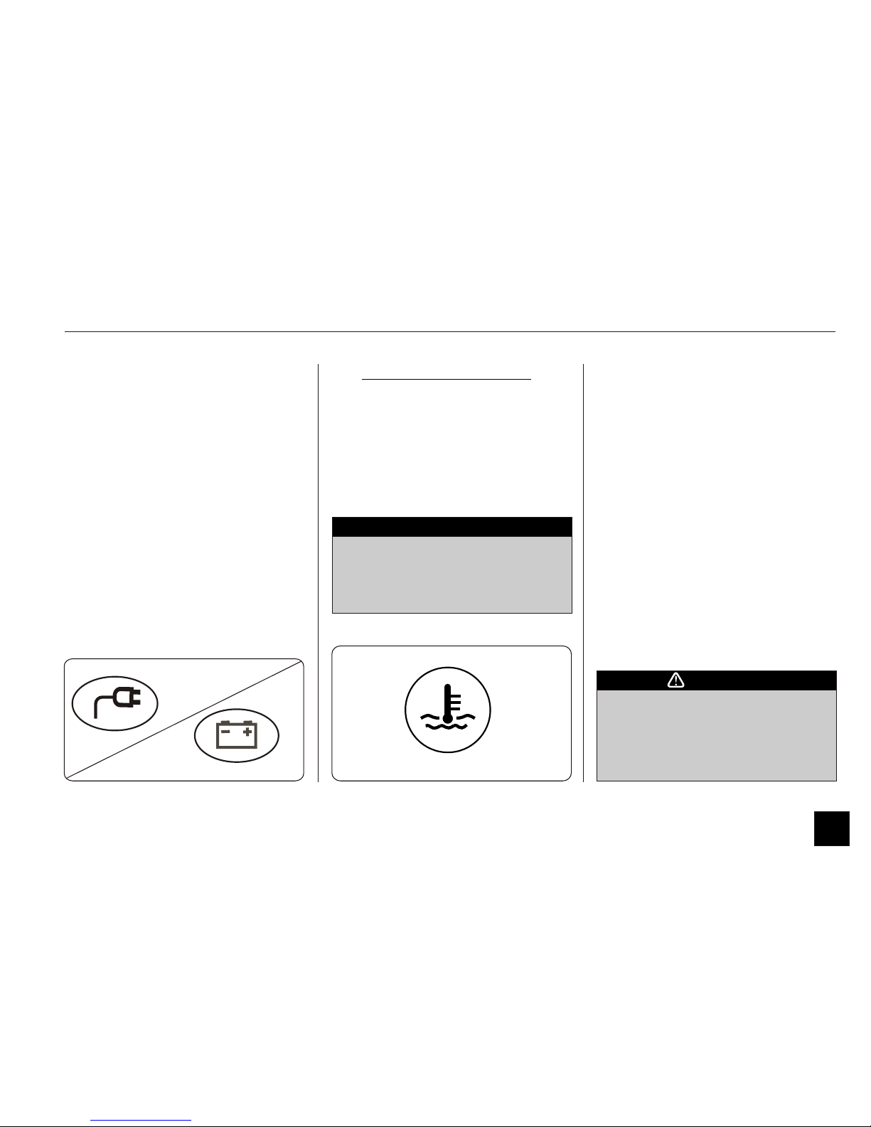
IV. TEMPERATURE LIGHT
If the light glows while driving, it
indicates overheating in either or all of
the following components:
1. Motor
2. Motor Controller
3. Power Pack
4. Charger
In cold climate, the temperature light
will flash during charge or drive, if
battery temperature is less than 10°C.
This indicates that the range of the car is
likely to be low.
When the car is not in use, keeping the
car plugged in to the utility supply
under this condition will activate the
battery heaters and warm up the
batteries.
While in charge, if the light
continues to glow/flash, it indicates
increased charging time due to high
Power Pack / Charger temperature.
NOTE
Do not charge your car in high
ambient temperature conditions or
in direct sunlight.
This will reduce the life of your
Power Pack.
CAUTION
.III. EQUALISATION (Alternate
between CHARGE LIGHT
and LOW BATTERY LIGHT)
Batteries are programmed to
automatically perform “Equalisation
Charge” once every 3-4weeks. This
ensures all individual batteries of power
pack are equalised. During this process,
Charge light and Low battery light will
blink alternatively.
When this process is complete, the
charge light will remain green.
It is advisable to allow the car to
continue until Charge light turns
permanently green. This process will
take 10Hrs and only after full charge.
CHARGE LIGHT
LOW BATTERY LIGHT
8
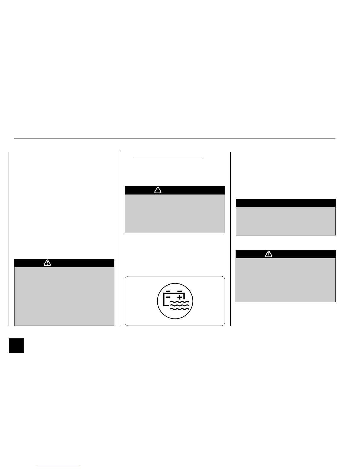
V. LOW BATTERY WATER
This lamp glows red when the water
level in the battery is low.
After the light comes ON you
should get the batteries watered
within the next 3 cycles. Failure to
do so will reduce the life of the
power pack and affect warranty.
CAUTION
If low water is sensed, the battery low
water light will come on for the first 5
mins of adrive.If watering is not carried
out following the next charge the low
water light willrepeat forthe next drive.
rd
If the battery is not watered after a 3
th
and journey then the BATTERY
LOW WATER light will flash every
seconds for theentirejourneyuntil the
batteries are watered.
4
2
1.1 Indicator Lights
Instrument Cluster and Controls
A flashing (ON/OFF) temperature light
during drive indicates a severe over
temperature condition and may
completely restrain the car.
If you continue driving the car,
electronics may reduce the speed and
power in order to limit the heating.
In any such a situation, switch the car
off and start again approximately after
15 min. If it continues to glow, it is
advisable to contact Goingreen
If you attempt to drive with the light
glowing red, you will notice that the
performance of your car is
reduced.
If you still continue to drive, the
temperature light will flash and your
car will soon come to a stop to
protect its drive train.
CAUTION
Low water sensing may be skewed by
parking on a slope. Please observe
during drive.
NOTE
ONLY water the battery when it is
fully charged and ONLY use distilled
or de-ionised water.
Not watering the car may VOID your
warranty, see Terms & Conditions of
Agreement.
CAUTION
9
1.1 Indicator Lights
Instrument Cluster and Controls
VI. SERVICE LIGHT
When the start-up key is turned ON,
this light should glow red and disappear
immediately. In the event it stays on, it
indicates that your G-Wiz requires
attention by Goingreen
The appearance of service light can be
due to a temperory condition detected
by EMS (On board computer). Please
continue using the car and inform your
nearest service center at the earliest
opportunity.
CAUTION
VII. NEUTRAL LIGHT
This light will be on when BFNR knob
is at ‘N’ position. This light will blink if
the key is switched on with control knob
in either B, F and R position. If this
light is blinking the car will not move.
Please turn the control knob to N and
then to desired mode to drive the car.
Ensure knob position in NEUTRAL
before start-up
NOTE
N
VIII. POWER INDICATOR
This light will come on GREEN during
regen and will glow RED when ever
more power is drawn from the battery.
This is an indication to driver to achieve
an optimum mileage out of G-Wiz by
gradual acceleration
IX. ENCODER FAULT LIGHT
This light glows during driving which
indicates a Drive system fault. Please call
Goingreen.
10
1.1 Indicator Lights
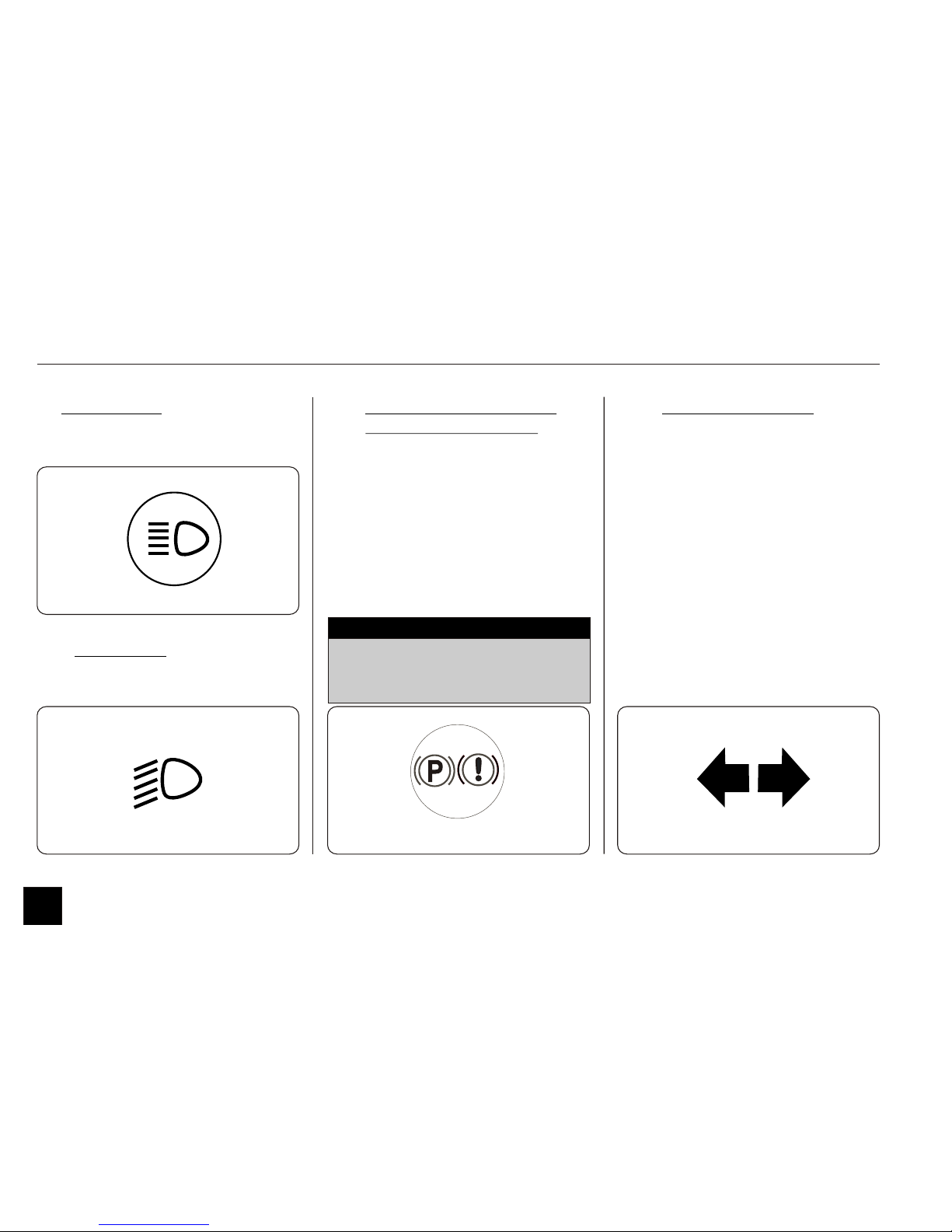
XII. PARKING BRAKE / LOW
BRAKE FLUID LIGHT
Parking brake light (P) with continous
alarm chime indicates you are driving
with the parking brake engaged.
Low brake fluid light (!) with
intermittent chime indicates low brake
fluid level. Please top up the brake fluid
at the first opportunity.
Instrument Cluster and Controls
X. HIGH BEAM
This lamp glows when the high beam
headlights are turned on.
XIII. TURN INDICATOR
The turn indicator light on the cluster
will flash when either of turn indicator
signalh ON or if hazard warning light
turned ON.
XI. LOW BEAM
This lamp glows when the headlights
are turned to low beam.
In the event this light continues to
glow irrespective of the above, please
contact Goingreen.
NOTE
11
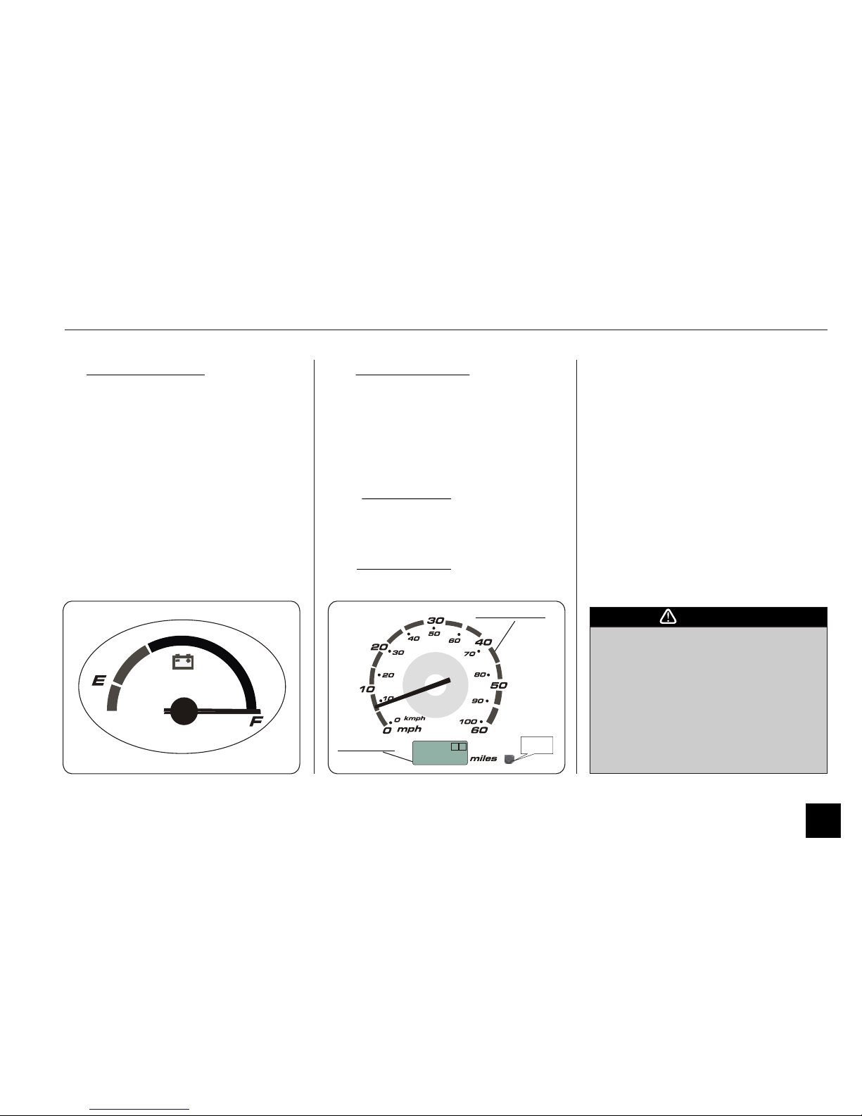
1.2 Gauges
I. POWER GAUGE
This gauge, like the fuel gauge in a
conventional automobile, indicates your
possible range of transportation with the
energy source available.
(Refer chapter on “Driving Your Car”).
Instrument Cluster and Controls
II. SPEEDOMETER
The outer perimeter (white) indicates the
speed of your car in miles per hour
(Mph) and the inner perimeter indicates
speed of your car in Kilometers per hour
(Kmph).
III. ODOMETER
The odometer records the total distance
in miles that your car has completed.
IV. TRIP METER
Trip meter can be used to measure the distance
traveled on short trips between stops..
Keep track of your odometer
reading and check the maintenance
schedule regularly for required
services. Increased wear or damage
to certain parts can result from
failure to perform required services
at the proper mileage intervals and
your warranty rights may be
affected.
CAUTION
SPEEDOMETER
ODOMETER
ODO TRIP
A
B
88888.8
Reset
button
12
Display Length
Total - 0 to 999999 miles
Trip A- 0.0 to 9999.9 miles
Trip B- 0.0 to 9999.9 miles
i) Total odometer will be displayed by
default.
ii) Push the reset button under 1.2
seconds, you can select Total -->Trip A
-->Trip B.
iii) Push the reset button over 1.2
seconds, display data is reset. Count start
from switch ON --->OFF. (Only at trip
odometer display)
1.3 Steering Wheel Controls
II. LOW BEAM / HIGH BEAM
To change between low beam and high
beam, pull the turn signal lever until you
hear a click, then let go. To flash the
high beam, pull the lever slightly
towards you and release it in a quick
action. Flashing the high beam is
necessary at times to warn traffic in the
front about your presence, especially
while overtaking at night.
Instrument Cluster and Controls
III. TURN SIGNALS
The turn signal lights blink when you
signal a lane change or turn.
Turn the side indicator lever upwards for
left turn and downwards for right turn
respectively.
I. HEADLIGHTS
This lever operating the headlights has
three positions. They are:
1. OFF - In this position, all lights are
off.
2. Middle Position - Front parking
lights, tail lights, registration plate
lights and dashboard backlighting is
lit but headlights remain off.
3. Third Position - The headlight also
comes on when the lever is turned to
this position.
FO
FFO
F
F
O F
13
1.3 Steering Wheel Controls
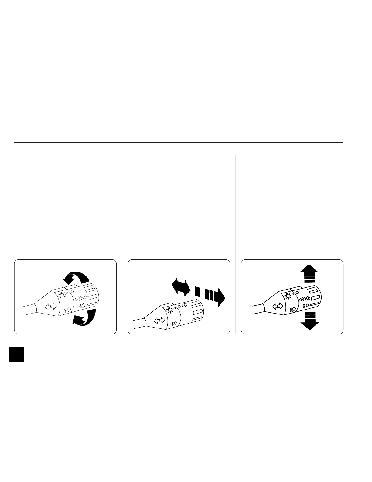
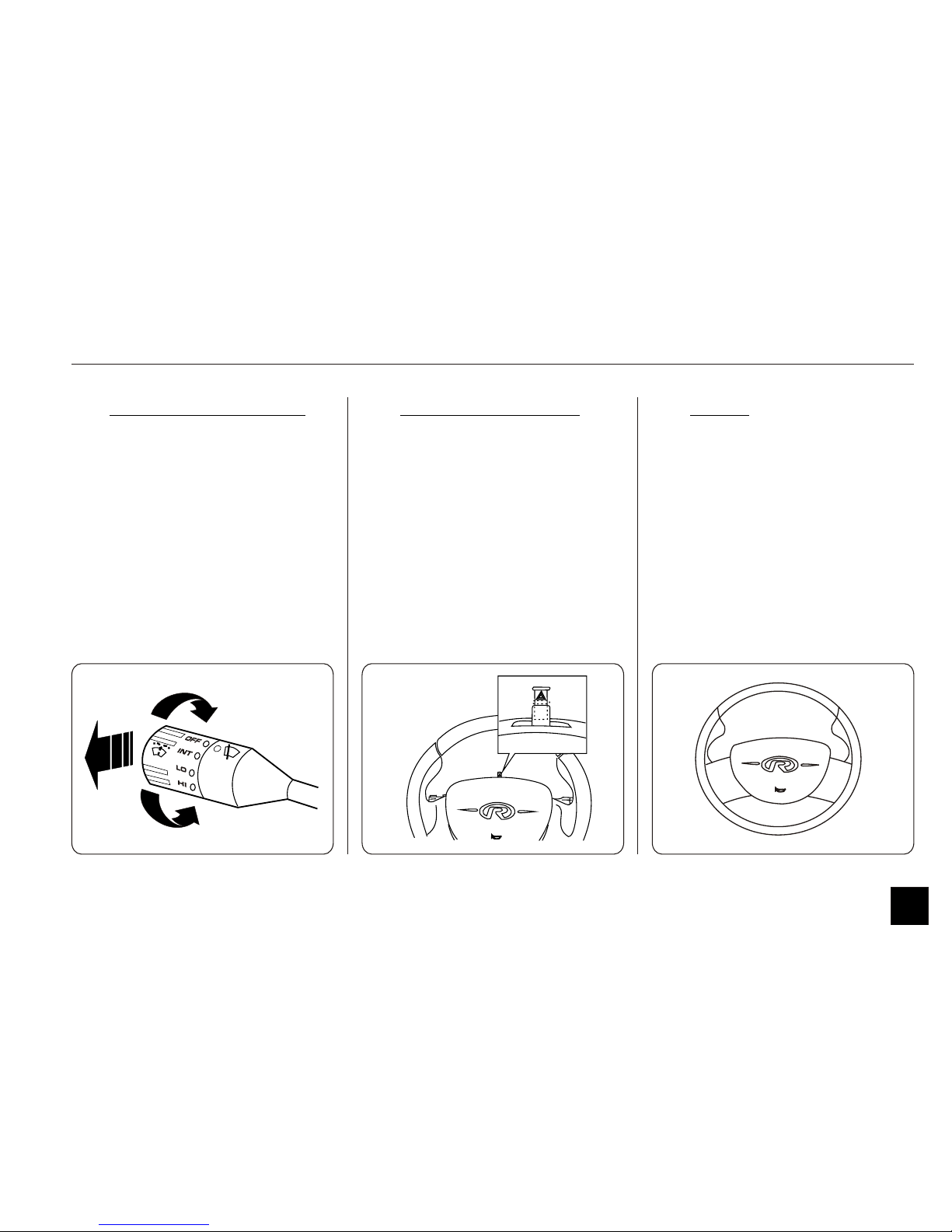
IV. WINDSCREEN WIPER
To operate the windscreen wiper, twist
the lever from OFF position to any of
the operating positions as required. The
speed of the wiper can be varied to
intermediate, low and high by operating
the lever switch.
To spray windscreen washer fluid, pull
the lever towards you, the wiper will
come ON for a few seconds/ wipes.
Instrument Cluster and Controls
V. HAZARD WARNING
Pull up the switch to activate the hazard
warning lights. All six external turn
signal lights and turn signal indicators
will flash simultaneously. To turn off the
lights, push the switch down. These
lights can be used to warn the traffic in
the event of any emergency.
VI. HORN
The horn is integrated in the center pad
of the steering wheel. Press anywhere on
this pad to sound horn.
P
L
U
L
P
L
U
L
14
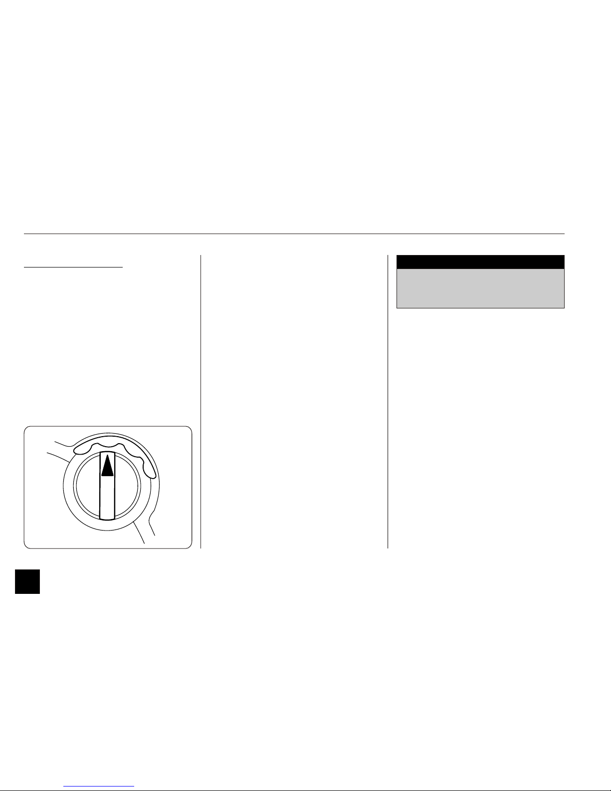
1.4 Control Knob
Instrument Cluster and Controls
CONTROL KNOB
The control knob of your car enables
you to choose the direction and speed of
movement.
It has the following positions:
Forward [F]:
This is the normal driving mode
position which enables you to move
forward. (max speed is 45mph) and
driving in this will give the best driving
range out of your car.
Power Boost [B]:
This mode is to be used ‘only’ if ‘Boost
Power’ is required. This position also
enables you to move forward direction,
will give you addition speed,
acceleration and hill climbing.
Neutral [N]:
The BFNR knob should be in this
position at the time of Key on and
should be used while parking your car,
or when you place your car in a
stationary position.
Reverse [R]:
When you rotate the control knob to
this position, your car would move in
the reverse direction. Your speed in this
position is limited to 12 mph.
(To know more about how to derive the
maximum range from your car, please refer
to section 4.0 on “Driving your Car”)
RR
BB
FF
NN
While climbing steep gradients, it is
advisable to switch over to ‘B’ mode
for better gradeability.
NOTE
15
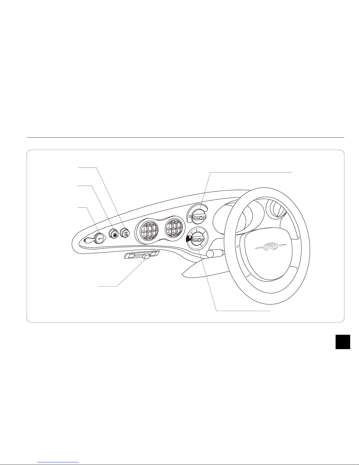
1.5 Climate Control System - controls
Instrument Cluster and Controls
11
22
33
44
BLOWER/DEFROSTER
SELECTOR LEVER
BLOWER/HEATER
KNOB
12V D.C.
SOCKET
DEFOGGER
SWITCH
REAR FOG
LAMP SWITCH
A/C VARIABLE
THERMOSTAT KNOB
16

11
22
33
44
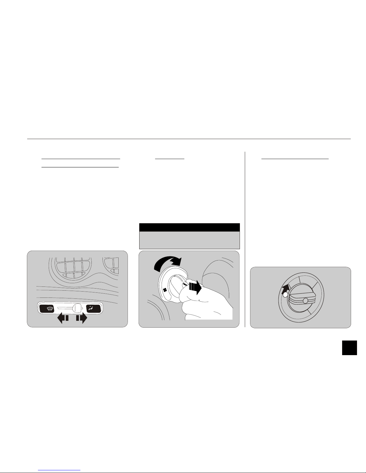
1.5 Climate Control System - controls
Instrument Cluster and Controls
I. AIR FLOW VENTS
The car is equipped with a blower
system with air flow vents provided to
circulate air in the car.
1. The central (circular) vents direct air
towards the cabin
2. The vents near the windshield direct
air towards it
3. The vents at the two corners of the
dashboard direct air onto the
windows.
II. BLOWER OPERATION
The Blower can be operated by turning
the knob from OFF position to any of
the desired 4 operating positions.
The louvers of the central vents can be
adjusted to direct the air for better
comfort.
Do not switch the blower on before
switching the car on.
Continuous use of the blower can
effect the range of the car.
NOTE
Always switch the blowers off
before turning the car off.
CAUTION
17
Instrument Cluster and Controls
V. A/C VARO SYSTEM*
This is an optional feature.
To operate the air conditioner, turn on
the blower and rotate the Varo Knob for
desired cooling position. Cool air will be
blown through the main vents gradually.
The A/C Varo knob is located below the
Blower switch and has a blue back light
in the ON condition. The Varo system
allows you to steplessly set the amount
of cooling you need and has an added
advantage in getting more mileage by
setting at low cooling.
11
22
33
44
IV. HEATER
To operate the Heater, pull the blower
knob gently towards yourself and turn it
to desired position.
The ‘HEAT’ symbol (in the center of the
knob) will light up.
Heater will automatically switch off at
25% SOC.
1.5 Climate Control System - controls
III. BLOWER/ DEFROSTER-
DEMISTER SELECTOR
The direction of air flow from the
blower can be changed by positioning
the Blower/ Defroster-Demister Selector
Lever.
Positioning this lever to the right directs air towards the cabin.
Positioning it to the left - directs air
towards the windshield and window acting as Defroster and Demister
respectively in Heater ON position.
Use on low setting to increase
mileage during drive
NOTE
18

Always remember to switch OFF the
Defogger switch once the hatch gets
cleared OR after 10 mins of
continuous operation.
Not doing so will reduce your driving
range significantly.
NOTE
Instrument Cluster and Controls
VI. REAR FOG LAMP
The car is fitted with a rear fog lamp to
enable other vehicles (coming from the
rear) to pin-point your car in foggy
weather conditions.
The rear fog lamp can be activated by
pressing the rear fog lamp switch
provided on the dashboard. Switch
symbol gets backlit when ON.
Press again to switch it OFF.
VII. REAR DEFOGGER
The rear hatch defogger will clear the
fog, frost or thin ice to give you a clear
rear view.
The defogger can be activated by
pressing the defogger switch provided
on the dashboard. Switch symbol gets
backlit when ON.
Press again to switch it OFF.
1.5 Climate Control System - controls
In case both - the Heater and the
A/C are ON at the same time , only
the A/C will function.
(i.e. the A/C overrides the Heater
and the Blower)
NOTE
Heater or A/C will not operate
when the car's SOC is less than
25% (Low Battery light starts
flashing).
Heater or A/C will not operate
when the car is in the Equalisation
mode.
NOTE
19

III. CHIME
The chime comes on under the
following circumstances:
1. Door/s is opened while the Key
Switch is ON.
2. Door/s is opened while the
headlights are ON (though Key
Switch is OFF.)
3. If Parking Brake is engaged, Key
Switch is ON and accelerator is
pressed.
4. Brake Fluid is low. (An intermittent
chime comes on in this case).
5. When you leave the car without
applying parking brake
i.e. Key Switch is OFF, door is open
and Parking Brake is not applied.
1.6 Keys / Key Switch / Chime
I. KEYS
Your car comes with two identical keys.
They fit all the locks on your car - Key
Switch and Doors. Each key has an
identification number stamped on it.
It is suggested that the key number is
noted down and stored in a safe place.
Instrument Cluster and Controls
II. KEY SWITCH
The key switch is on the right side of the
steering column.
It has 2 positions:
1. Lock (OFF):
The key can be inserted and removed
only in this position.
2. ON:
When you turn the key to this
position all electrical features in your car
will come on.
KEY SWITCH
20
1.7 Door Locks
Instrument Cluster and Controls
DOOR LOCKS -
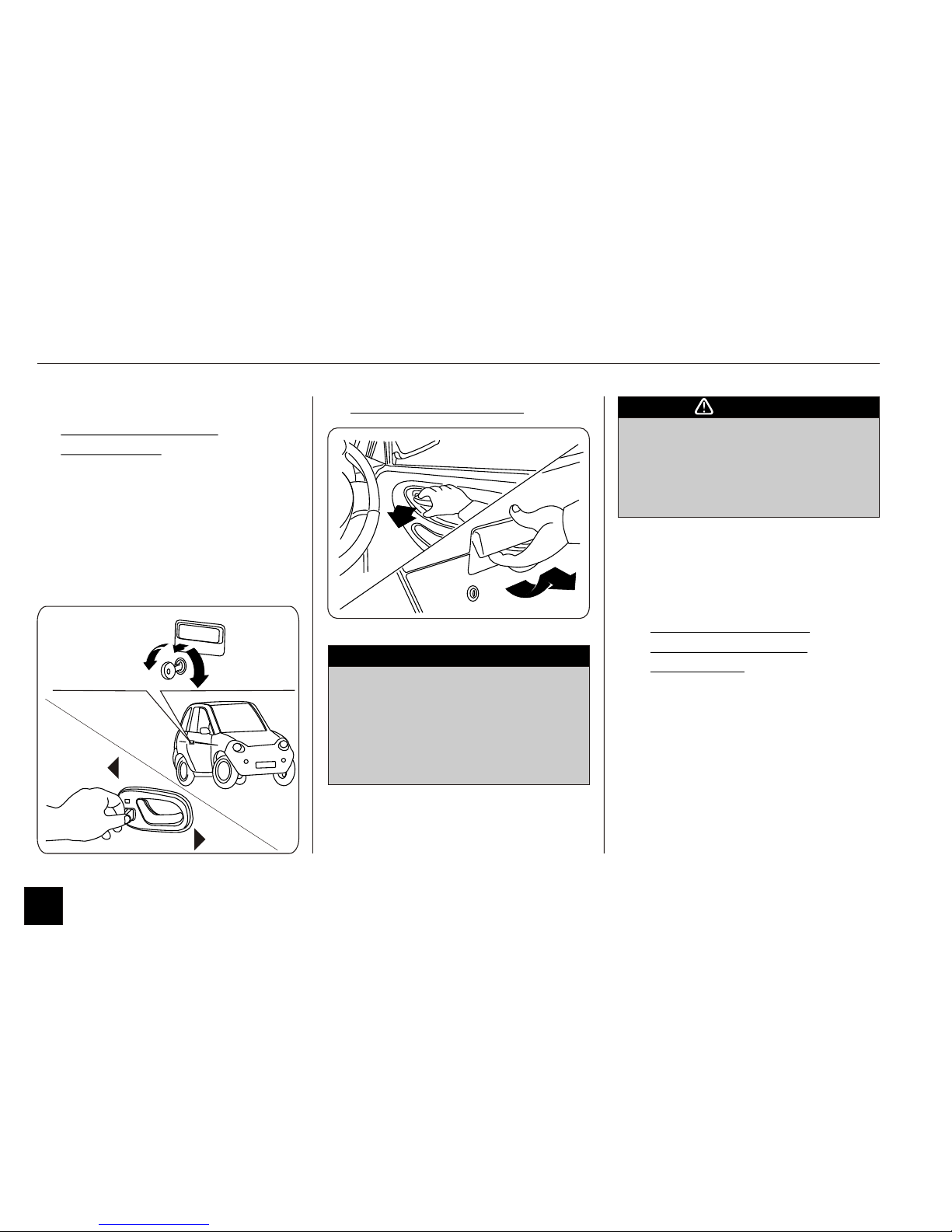
I. TO LOCK/ UNLOCK
MANUALLY:
To lock or unlock your car manually,
turn the key in the clockwise or anticlockwise direction respectively as
shown in the figure.
To lock from inside, push door lock
lever towards front of car and push it
back to unlock as indicated in the figure.
Always ensure to lock both the
doors while driving.
Locking the doors will guard the
occupants from being thrown out in
case of accidental opening of a door.
CAUTION
II. TO OPEN THE DOOR:
UNLOCK
(anti-clockwise)
LOCK
(clockwise)
UNLOCK
LOCK
Your car has been equipped with
factory fitted central door locking
(CDL) system. Hence the keys must
be used to lock/unlock the doors
only when the CDL system is not
functional.
NOTE
III. TO LOCK/ UNLOCK
AUTOMATICALLY USING CDL
Your Car is fitted with a Central Door
Locking (CDL) system, which has the
following features:
1. Remote lock/ unlock of car.
2. Immobiliser.
3. Remote car heating/cooling*.
(continued)
21
1.7 Door Locks - Central Door Locking System
Instrument Cluster and Controls
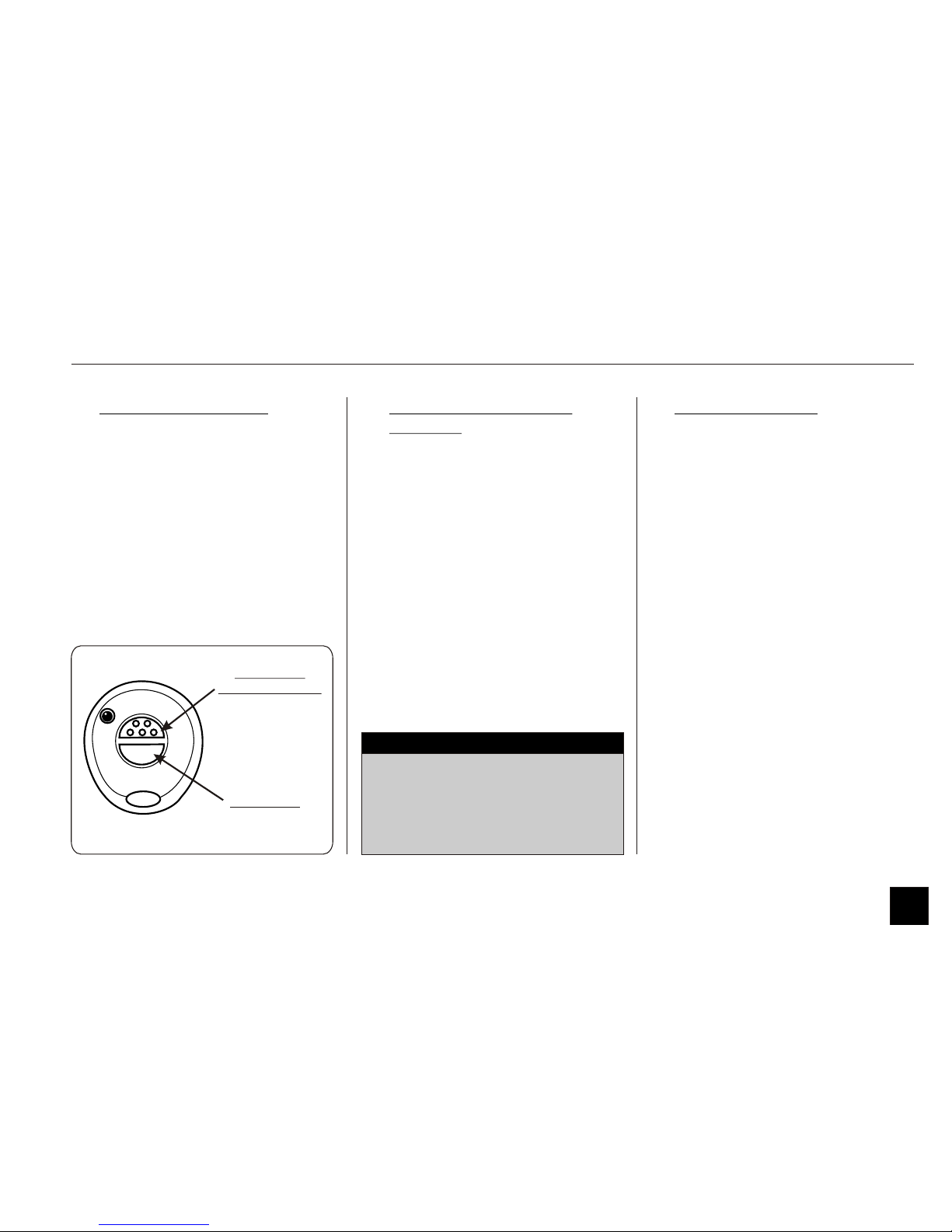
1. Operation with Remote:
The car can be locked or unlocked by
pressing Button 1 on the remote unit.
A locking action is accompanied by a
single 'Flash’ of Turn indicator lights,
Unlocking action is accompanied by 3
flashes of Turn indicator lights.
It is advisable to operate the remote
while the car is within visual range,
as the car’s alarm system is of the
visual type (turn indicators flash) and
NOT the audible (siren) type.
NOTE
2. Automatic Door Locking/
Unlocking (*if programmed)
1. Doors get locked automatically after
20 sec. when you turn ON the Key
Switch (provided the doors are
closed and the car is in the disarmed
condition).
2. Doors get locked automatically after
30 sec., once it is unlocked by the
remote.
3. Doors get unlocked automatically
when you turn OFF the Key Switch.
‘BUTTON 1’
LOCK / UNLOCK
‘BUTTON 2’
22
3. Car ‘Armed’ Position
After 45 seconds of locking operation
car enters in to ‘armed’ condition and
CDL system LED indicator flashes
continuously. Any attempt to do the
following events causes alarm:
i) Cutting of system wire.
ii)Disturbing the UN-switched supply
loads.
iii)Attempt to turn ON key switch.
iv)Attempt to open the doors.
V) Panic alarm – by pressing Button2
on the remote.
Under alarm conditions, flashes will
come for 30 seconds, and heater comes
ON with blower running at 4th speed.
If the event is still happening even after
30 seconds, then flashes continue for
further 30 seconds.
CDL
LED INDICATOR
1.7 Door Locks - Central Door Locking System
Instrument Cluster and Controls
4. Neutral Time
The CDL system has a ‘Neutral time’ of
45 sec. after ‘Lock’ operation. During
this neutral time, the system allows you
to unlock the car manually, get in and
out of the car, without raising an alarm.
During the neutral time however, the car
stays immobilized - the CDL-LED
glows continuously to indicate this.
5. Immobiliser action:
When the car is armed, it can only be
unlocked using the remote. Any attempt
to start the car by other means is
blocked by the CDL. The car stays
immobilized if - one attempts to switch
ON the key switch when the car is in
the ‘Armed’ condition. The car also gets
automatically ‘Armed’ after a 75 sec.
delay, if the Key Switch is in the OFF
position and the doors are closed.
1. Close doors properly while
coming out of the car.
2. Do not turn the Key Switch ON
when the doors are open - this
makes remote button disabled
even after the Key Switch is
switched OFF.
This situation is indicated by the
continuous glow of the CDL-LED.
CAUTION
1.There should be a 5 sec. gap
between any two operations with
the remote.
2.The CDL system does not provide
master motor function.
NOTE
Remote is lost or is not functioning/
Keys are lost - Contact Goingreen at
once.
NOTE
23
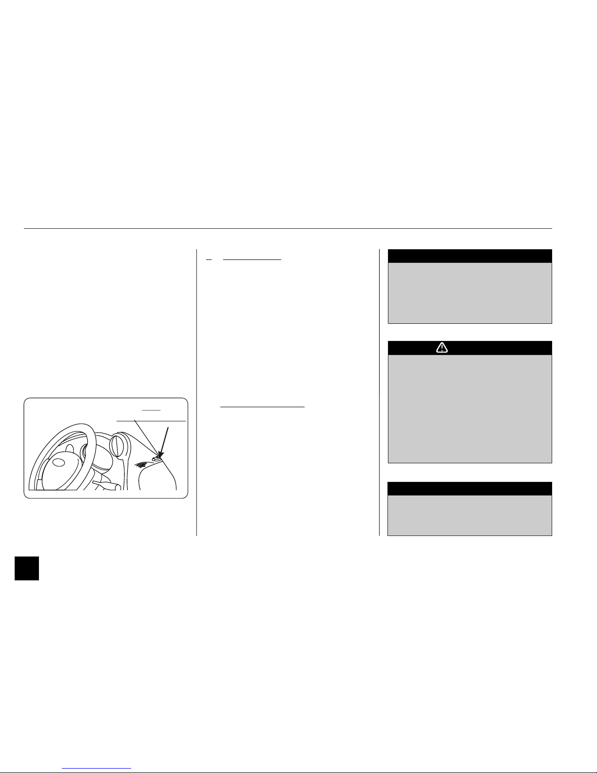
CDL system LED Indicator:
The CDL system LED indicator is
located in the right hand corner on top of
the dashboard / front windshield.
i) This LED will be ‘flashing’ in armed
condition.
ii) It will be ‘unlit’ in disarmed condition.
iii) During Neutral time, the LED will
glow continuously.
Iv) The LED will also glow continuously
if doors are opened in disarmed
condition.
1.8 Seat Adjustments
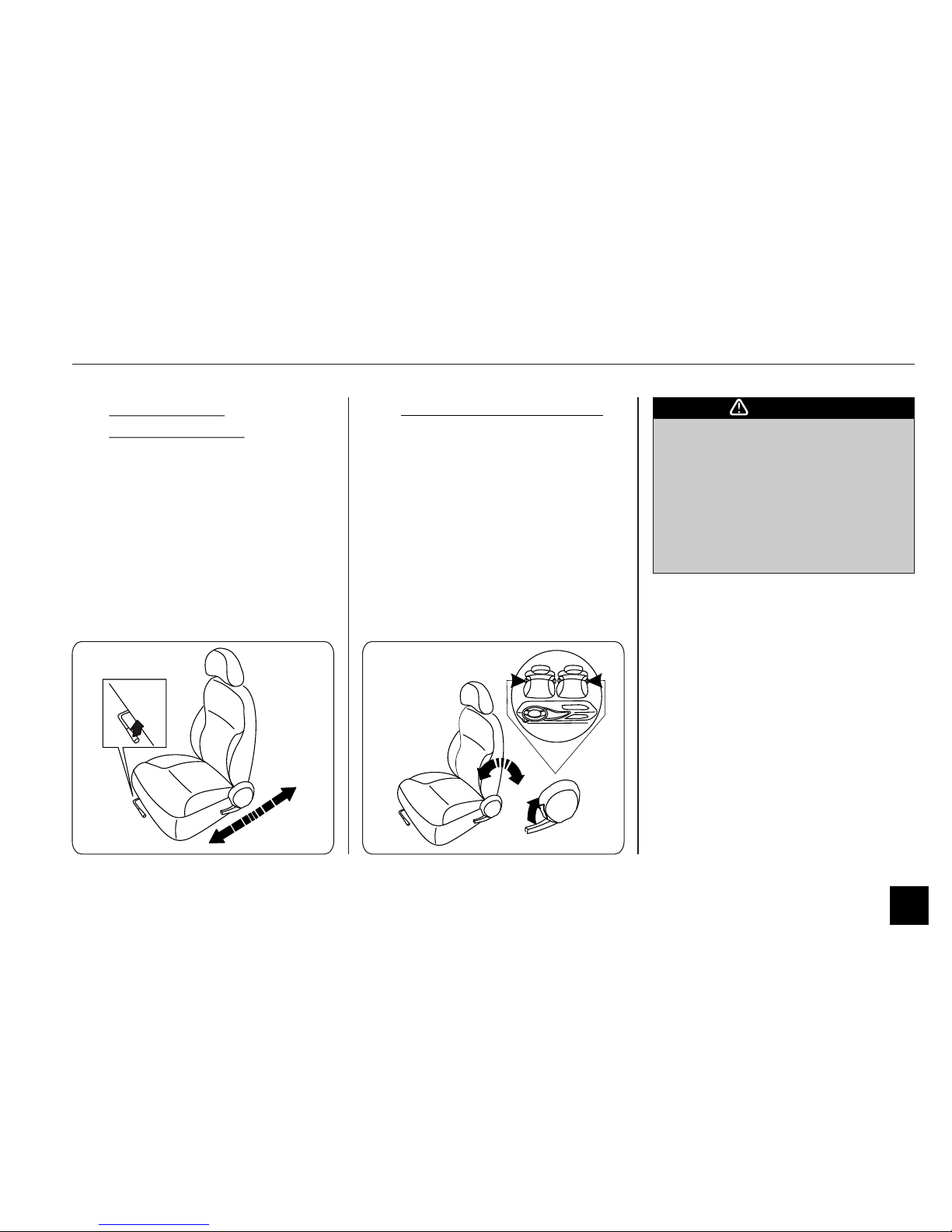
I. FRONT SEAT
ADJUSTMENTS
Find a driving position, which is most
comfortable for you. The adjustment
lever for each of the front seats is located
in the front, under the right side of the
driver’s seat and left side of the
passenger’s seat.
To adjust, pull the lever up and slide the
seat forward or backward.
Instrument Cluster and Controls
II. RECLINING THE SEAT
The seat back can be reclined to four
different angles by pulling a lever located
on the right hand side of the driver’s
seat and the left-hand side of the
passenger’s seat.
The position of seat backs should
always be in an upright position
when driving, or seat belt
effectiveness may be reduced.
Always adjust the seats before
driving. Never attempt to adjust
seats while driving.
CAUTION
24
1.8 Seat Adjustments
Instrument Cluster and Controls
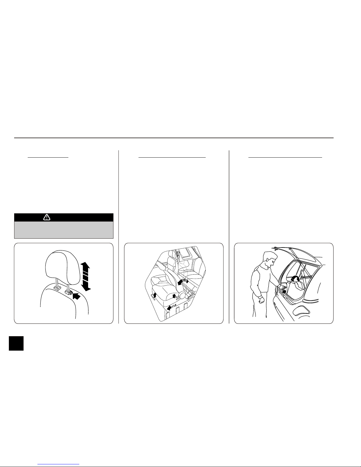
III. HEAD REST
The head rest can be adjusted for height
with the help of the button located on it.
To raise, pull the headrest upward to a
level most comfortable for you. To lower
it, press the button and push the head
rest down.
IV. REAR SEAT ACCESS
You can access the rear seats from both
sides of your car. To do so:
Step 1: Pull up the seat adjustment
lever of the respective front seat
and slide the seat forward.
Step 2: Recline the seat forward to
allow easy entry to the rear seat.
Step 3: Make sure the front seat is
returned back to the normal
position.
It is dangerous to drive without head
rest.
CAUTION
V. FOLDING REAR SEAT
Step 1 : To get additional luggage
space, detach the two rubber
latches located behind the rear
seat.
Step 2 : Fold the backrest forward.
Step 3 : When not required lift backrest
and push back to normal
position attaching the rubber
latches.
25
1.8 Seat Adjustments
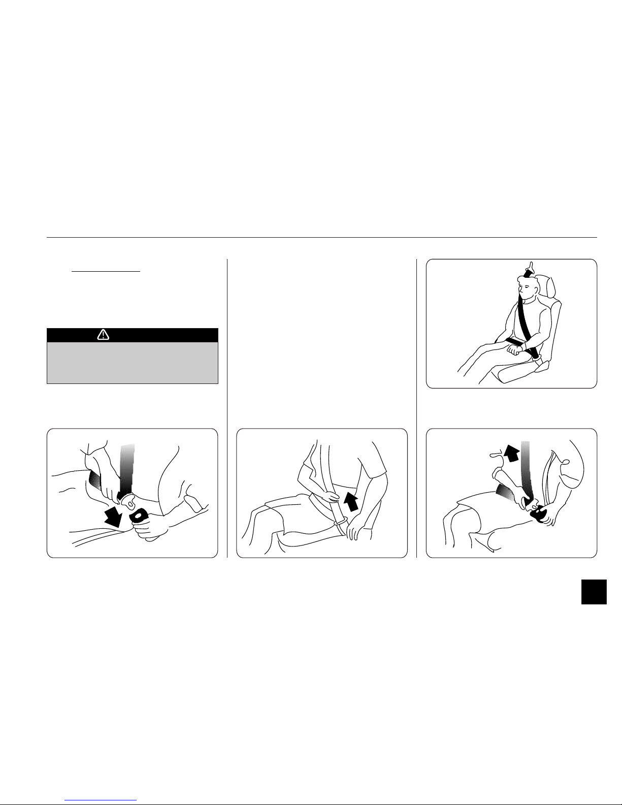
VI. SEAT BELTS
Both front and rear seats of your car
have been fitted with safety belts for
maximum protection from any
inadvertent event.
Instrument Cluster and Controls
The following steps may be followed.
Step 1: Adjust the seats so you can sit
up straight.
Step 2: Pull the belt across you and
insert the latch plate into the
latch slot. Make sure the belt is
securely latched. Also check that
the belt is not twisted.
Step 3: Position the lap belt as low as
possible across your hips. Then
pull and adjust the shoulder belt
so they both fit snugly.
To unfasten the belt, press the release
button on the latch slot.
Make sure all seat-belts are properly
fastened before driving, for your
safety.
CAUTION
The Rear seat belts are static type.
Manually adjust them according to the
comfort of the occupant to fit snugly.
26

1.8 Seat Adjustments
Instrument Cluster and Controls
NOTE
Make sure you remove hard or
breakable objects lying in pockets or
clothing, if any, before wearing
seatbelts.
The seatbelt is equipped to be used by
one person only. Never use seat belts
for more than one occupant
Ensure that the seat belt straps are not
twisted while in use.
Pregnant woman are recommended to
wear seat belt for protection. Please
consult your doctor for any specific
recommendations.
Never attach the seat belt over a child
or infant in the occupant’s lap.
Child restraint system:
Children and infants must never be
transported without a proper restraint
system. This system can be purchased
from the market. Ensure that the
system purchased meets all the
applicable standards and safety
measures. Use as per instruction of the
manufacturer while seating the child in
the front seat.
Cleaning the seat belts:
Never use any harsh detergents to clean
the seat belt as this may render them
ineffective.
Inspect the seatbelts regularly for
excessive wear and tear. If any
damages/ frays etc are found, replace
the seat belt immediately.
Do not attempt to tamper the seatbelts
as this may affect the performance of
the seat belts.
27
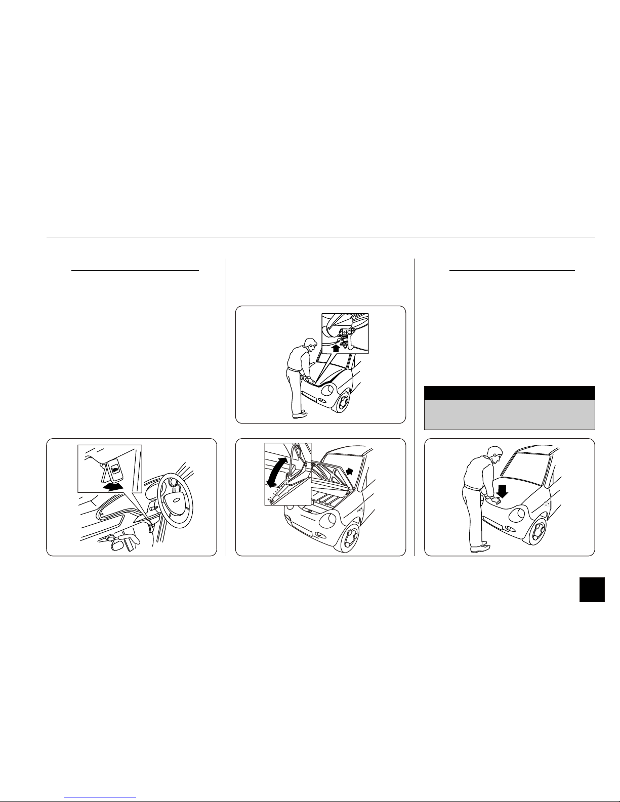
1.9 Hood
I. OPENING THE HOOD
Step 1: Pull the hood release lever
located beneath dashboard on
right side of steering column.
Step 2: Locate the hood-latch lever
under the middle edge of the
hood with your finger. Pull
this lever until it releases hood.
Step 3: Lift the hood and pull the
hood support-rod out of its clip
and insert the end into its
housing on the passenger’s side
Instrument Cluster and Controls
II. CLOSING THE HOOD
Step 1: Lift it up slightly to remove the
support rod.
Step 2: Put the support rod back into
the holding clip.
Step 3: Lower the hood till it touches
the fender and press it lightly.
Do not bang the hood. Ensure that
the hood is fully locked before driving
NOTE
28
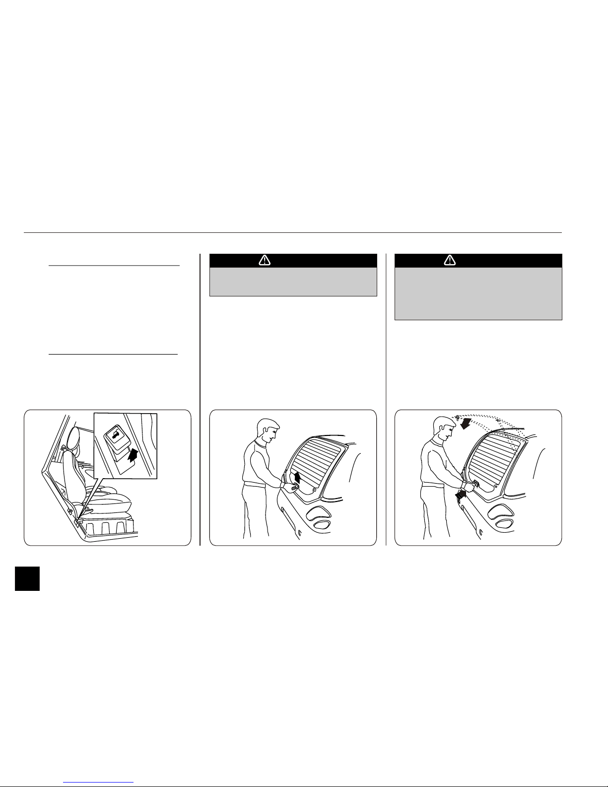
1.10 Rear Hatch
Instrument Cluster and Controls
I. OPENING THE HATCH
Pull the hatch release lever located below
the door latch on the doorframe on the
driver’s side. Lift the hatch.
II. CLOSING THE HATCH
Gently press hatch down until it locks
into position.
Do not bang the hatch.
Secure the hatch fully before driving.
CAUTION
Be very careful of the hatch-catcher
when hatch is in the open/raised
condition.
You might get seriously hurt.
CAUTION
29
 Loading...