

GoGaS Goch KMI 20 - 1, KMI 40 - 1, KMI 60 - 1, KMI 90 - 1, KMI 120 - 1 Installation, Operation And Service Instructions
...
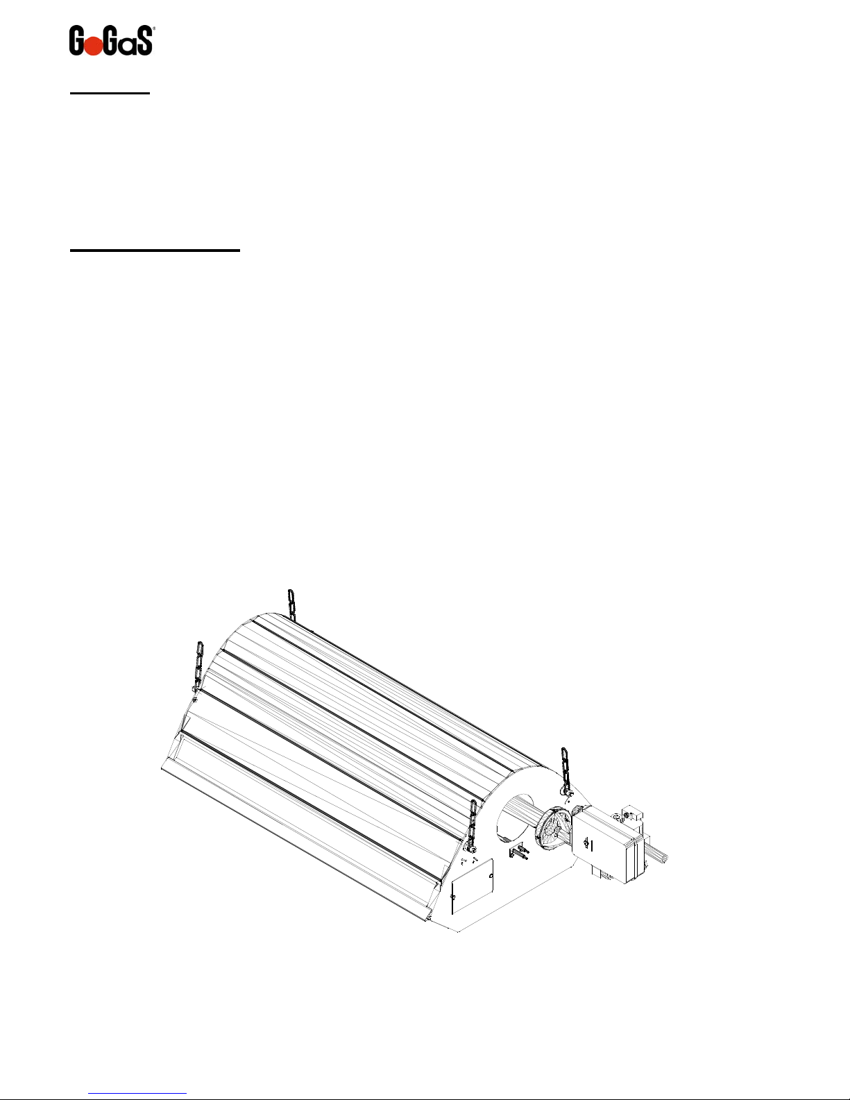
Series KMI High Intensity Heater
Installation, Operation and Service Instructions
KMI 20 - 1
KMI 40 - 1
KMI 60 - 1
KMI 90 - 1
KMI 120 - 1
GoGaS Goch GmbH & CO. KG
Zum Ihnedieck 18
44265 Dortmund - Germany
Phone +49 231 46505-0
Fax +49 231 46505-88
FOR YOUR SAFETY
If you smell gas:
1. Open windows
2. Don´t touch electrical switches
3. Extinguish any open flame
4. Immediately call your gas supplier
CONSIGNES DE SECURITE
Si vous sentez une odeur de gaz:
1. Ouvrez les fenêtres
2. Ne touchez pas aux interrupteurs
électriques
3. Éteignez tout flamme nue
4. Contactez immédiatement votre
fournisseur de gaz
Read and thoroughly understand these instructions before attempting any installation.
Retain this manual for reference.
Installer
Owner
FOR YOUR SAFETY
Do not store or use gasoline or other
flammable vapors and liquids in the
vicinity of this or any other appliance.
CONSIGNES DE SECURITE
Il est interdit d’utiliser des liquides
inflammables ou dégageant des
vapeurs inflammables, a proximités
de tout appareil fonctionnent au gaz.
Goch GmbH & Co. KG
Improper installation, adjustment, alteration, service or maintenance can cause injury, death
or property damage. Read the installation, operation and service instructions thoroughly
before installing or servicing this equipment.
WARNING
Superior Radiant Products
www.superiorradiant.com
LT152 November 4, 2013
CAUTION: FIRE OR EXPLOSION HAZARD
Maintain clearance to combustible constructions as further specified in this manual.
Failure to do so could result in a serious fire hazard. Heaters should not be located in
hazardous atmospheres containing flammable vapours or combustible dusts. Signs
should be provided in storage areas specifying maximum safe stacking height.
CAUTION: MECHANICAL HAZARD
This equipment is designed and approved for indoor use only. This product is not
intended to be installed indoors in residential applications.
CAUTION: FIRE OR EXPLOSION HAZARD
This heater equipped with an automatic ignition device. Do not attempt to light the
burner by hand. Failure to comply could result in a serious fire and personal injury
hazard.
CAUTION: MECHANICAL HAZARD
Do not use high pressure (above ½ psi) to the test gas supply system with the burners
connected. Failure to do so could results in damage to the burner and its control
components requiring replacement.
CAUTION: SERVICE LIFE RISK
Do not install equipment in atmospheres containing halogenated hydrocarbons or other
corrosive chemicals. High intensity heaters are not recommended for installation in
enclosed swimming pool areas. Failure to do so may lead to premature equipment
failure and will in-validate the warranty.
Serires KMI - 2 - November 4, 2013

Goch GmbH & Co. KG
TableofContents
PREFACE.......................................................................................................................................4
THETECHNOLOGY........................................................................................................................4
IMPORTANT.................................................................................................................................5
GENERALINFORMATION..............................................................................................................5
NSTALLATIONCODES.........................................................................................................................................5
I
G
ENERALINSTALLATIONANDGASCODES/ELECTRICALCODES...................................................................................5
A
IRCRAFTHANGARINSTALLATION........................................................................................................................5
P
UBLICGARAGES...............................................................................................................................................5
P
ARKINGSTRUCTURES........................................................................................................................................5
ARNING:........................................................................................................................................................5
W
LAYOUTCONSIDERATIONS...........................................................................................................6
S
POTHEATING..................................................................................................................................................6
S
UGGESTEDHEATLOADINGFORINDOORSPOTHEATINGUNDERSTATEDCONDITIONS:...................................................7
F
ULLBUILDINGHEAT..........................................................................................................................................7
ENGINEERINGSPECIFICATIONS.....................................................................................................8
E
NERGYSUPPLY.................................................................................................................................................8
M
INIMUMCLEARANCESTOCOMBUSTIBLES...........................................................................................................9
INSTALLATIONSINSTRUCTIONS..................................................................................................10
H
IGHINTENSITYMOUNTINGINSTRUCTIONS/CONFIGURATIONS.............................................................................10
HorizontallyMountedHighIntensityHeater...........................................................................................................10
Angledhighintensityheater....................................................................................................................................12
A
IRPLATEINSTALLATIONINSTRUCTIONS..............................................................................................................13
Procedure:................................................................................................................................................................13
ASCONNECTIONS..........................................................................................................................................14
G
LECTRICALCONNECTIONS................................................................................................................................15
E
Single‐stageelectricalconnection/WiringDiagram..............................................................................................16
ENTILATION...................................................................................................................................................17
V
ONDENSATION............................................................................................................................... ................17
C
OPERATION................................................................................................................................18
S
INGLE‐STAGEHIGHINTENSITYHEATER...............................................................................................................18
ControlOperatingSequence....................................................................................................................................18
Controlling/CheckingManifoldPressure...............................................................................................................18
NNUALMAINTENANCE...................................................................................................................................19
A
TROUBLESHOOTING...................................................................................................................20
REPLACEMENTPARTSECTION....................................................................................................21
WARRANTY................................................................................................................................22
Serires KMI - 3 - November 4, 2013
Preface
GoGaS high intensity heaters represent an efficient and comfortable alternative to conventional
heating systems. The infrared gas fired heater is an atmospherically operated infrared heater
which converts most of the energy applied (natural gas or LPG) into thermal radiation. The
sensible radiation component within the vicinity of persons allows a reduction in the air
temperature, thus leading to energy savings.
The Technology
The GoGaS KMI Novus high intensity heater from the KMI series is a high-quality product with
ratings from 6 kW (21,000 BTU/h) to 36 kW (125,000 BTU/h). The modern injector burner allows
almost pollution-free operation, from the smallest to the largest heater unit, with only one
combustion chamber. The stainless steel combustion chamber is integrated in an insulated
hood. The hot waste gases collect under the hood and pre-heat the gas-air mixture in the
combustion chamber, leading to a maximum degree of radiation. The reflector is made of highly
reflecting material and directs the captured radiation towards the vicinity of persons.
Serires KMI - 4 - November 4, 2013
Goch GmbH & Co. KG
Important
This appliance must be installed in accordance with current connection and installation
regulations and may only be used in adequately ventilated rooms. The installation and operating
instructions must be inspected and understood before installation and before start-up.
Before installation it must be checked whether local gas distributions, gas types and gas
pressures as well as the settings of the appliance are compatible.
Important
These instructions, the layout drawing, local codes and ordinances, and applicable
standards such as apply to gas piping and electrical wiring comprise the basic information
needed to complete the installation, and must be thoroughly understood along with general
building codes before proceeding.
Only personnel who have been trained and understand all applicable codes should
undertake the installation. SRP Representatives are Factory Certified in the service and
application of this equipment and can be called on for helpful suggestions about installation.
General information
GoGaS infrared heaters are manufactured in accordance with ANSI Z83.19-2009/CSA 2.35-
2009. Each appliance is subjected to a function test before it leaves the factory and is preset to
the relevant gas type. For setting up and operating radiation equipment, the following
regulations and guidelines must be complied with.
This heater maybe approved for either indoor or outdoor installation. Not for use in
residential dwellings, refer to Rating plate.
Installation Codes
The installation must conform with local building codes or, in the absence of local codes, with
the National Fuel Gas Code, ANSI Z223.1/NFPA 54, or the Natural Gas and Propane
Installation Code, CSA B149.1.
General Installation and Gas Codes/Electrical Codes
If an external electrical source is utilized, the heater, when installed, must be electrically
grounded in accordance with the National Electrical Code, ANSI/NFPA 70, or current Canadian
Electrical Code, CSA C22.1.
Aircraft Hangar Installation
Installation in aircraft hangars must conform to the Standard for Aircraft Hangars, NSI/NFPA 409
in the US and CAN/CGA B149.1 and B149.2 Installation Codes in Canada
Public Garages
Installation in public garages must conform to the Standard for Parking Structures, NFPA 88A or
the Standard for Repair Garages, NFPA 88B, in the US and CAN/CGA B149.1 and B149.2
Installation Codes in Canada.
Parking Structures
Technical requirements are outlined in ANSI/NFPA 88A (USA)
Warning: Heaters should be installed so that the minimum clearances marked on the heater will
be maintained from vehicles parked below the heater.
Serires KMI - 5 - November 4, 2013

Layout Considerations
1. Because high intensity heaters are un-vented, ensure that adequate ventilation will be
available; most codes require a minimum of 4 cfm per 1000 BTUH of installed heat
capacity in natural gas, 4.5 cfm per 1000 BTUH for propane. Also see section on
Ventilation.
2. Check local codes for mounting requirements and the requirement for flexible gas
connectors or rigid mounting.
3. Do not locate heaters near windy locations such as door openings.
4. Do not locate heaters in very dusty environments
5. Avoid placing heaters below sprinkler heads or provide more than adequate clearance.
Spot Heating
High intensity heaters are ideal for spot heating applications. The following are key
considerations to the success of the application:
1. Minimize any wind in order to maximize the effect of the radiant heat.
2. Placing two smaller heaters opposing each other will be more c omfortable than placing
one large heater.
3. Hang the heaters back and at an oblique angle (rather than directly overhead) in order to
maximize the exposure of the peoples’ bodies to radiant heat.
The following charts are intended for guidance only. Specific applications may require other
parameters.
Suggested Minimum Mounting Heights
Heater Input
Mounting Angle
Rate
0° – 10° 30°
BTU/hr
ft m ft m
20,000 10 – 15 3 – 4.6 9 – 13 2.7 – 4
40,000 12 – 19 3.7 – 5.9 11 – 17 3.4 – 5.2
60,000 14 – 22 4.3 – 6.7 13 – 19 4 – 5.9
90,000 15 – 24 4.6 – 7.3 14 – 22 4.3 – 6.7
120,000 17 – 29 5.2 – 8.8 16 – 25 4.9 – 7.6
Serires KMI - 6 - November 4, 2013

Suggested heat loading for indoor spot heating under stated conditions:
BTU/hr per sq. ft of
Ambient Air
Temperature
At 50 ft/min of wind
(15.2 m/min)
Floor Area to be Heated
At 100 ft/min of wind
(30.5 m/min)
40°F / 4°C 150—165 165—180
55°F / 13°C 75—88 85—100
Example:
Work counter for light assembly, space is 15 ft x 25 ft. (4.5 m x 7.6 m),
ambient air temperature 40°F / 4C, located near shipping doors.
Approximately 170 BTUH/sq.ft x (15x25) sq.ft = 63,750 BTUH
Two heaters at opposing locations would be preferred
Goch GmbH & Co. KG
Full Building Heat
Calculate the total heat input required, ensuring the inclusion of any unheated make-up air due
to exhaust fans. Use the following chart as guidance to heater placement.
Model/BTUH KMI-20 KMI-40 KMI-60 KMI-90 KMI-120
Heater
Mounting
Height,
ft (m)
Mounting
Angle 0°-10°
Mounting
Angle 30°
Distance of first heater
row
from outside wall, ft (m)
Distance between heaters
along outside wall*, ft (m)
Distance between rows –
out-side wall row to next
interior row, ft (m)
10-15
9-13
6
(1.9)
8-20
(2.5 – 6.1)
30-60
(9.2 – 18.3)
12-19
11-17
10
(3.1)
15-30
(4.6 – 9.2)
50-80
(15.2 – 24.4)
14-22
13-19
12
(3.7)
20-40
(6.1 – 12.2)
75-110
(22.9 – 33.5)
15-24
14-22
14
(4.3)
30-50
(9.2 – 15.2)
90-115
(27.5 – 35.0)
17-29
16-25
16
(4.9)
40-60
(12.2 – 18.3)
100-125
(30.5 – 38.1)
* Distance between heaters along interior rows should be up to twice the indicated number
Serires KMI - 7 - November 4, 2013
 Loading...