

Page 1

SP-1
Quick Start Manual
Page 2

STATISTICS
PLEASE READ CAREFULLY
VITAL STATISTICS
LENGTH/HEIGHT/WEIGHT:
OPERATING PRESSURE:
PAINTBALLS:
POWER SOURCE:
PROPELLANT:
RATE OF FIRE:
OPERATION:
MODES OF FIRE:
ANTI CHOP SYSTEM:
BARREL THREAD:
LUBRICANT:
12.5”/ 7.5”/ 2lb, 5oz
Approx 160 to 200 psi max
.68 caliber – Compliant to ASTM F1979 Specication
9-volt alkaline battery
CO2 or Nitrogen/Compressed Air
Up to 11bps
Low-Pressure Electropneumatic
Semi-Automatic
Low Bolt Pressure
Smart Parts (Impulse/Ion
For proper and consistent operation, the SP-1 should only be lubricated with
SL33K lubricating grease.
MAINTENANCE
The SP-1 has been designed with simplicity in mind so that you can concentrate on your game instead of
your marker. It has a minimal number of moving parts and seals so that you can maintain the marker with
little effort. This DOES NOT mean that you should neglect your marker. If you take care of it off the eld,
your SP-1 will take care of you on the eld. For best performance, clean and grease your SP-1 frequently.
Many players clean their marker after every use. While this may seem a bit extreme, being vigilant in the
upkeep of your marker will extend its useful life considerably. Playing in the rain will not damage your
SP-1, but you should NEVER immerse it in water. If your marker should become waterlogged, remove the
barrel, body cover and rubber grips and allow them to dry out, then follow the disassembly instructions for
full cleaning. Clean out mud and paint with a damp cloth and alcohol. Grease the SP-1 ONLY with SL33K
pneumatic grease. For best performance, use high quality paintballs.
While every effort has been made to ensure
that the information contained in this guide
is accurate and complete, no liability can be
accepted for errors or omissions.
Smart Parts, Inc. reserves the right to
change the specifications of the SP-1 at any
time without prior notice. The latest version
of this manual may be downloaded free of
charge at www.smartparts.com.
00
800.922.2147 www.smartparts.com
Page 3

SP-1 WARNINGS
– THE SP-1 IS NOT A TOY.
– MISUSE OF THE SP -1 MAY RESULT IN SERIOUS INJURY OR DEATH.
– EYE PROTECTION SPECIFICALLY DESIGNED FOR PAINTBALL USE MUST BE IN COMPLIANCE
WITH ASTM SPECIFICATION F1776 AND MUST BE USED BY THE USER AND ANYONE WITHIN
RANGE OF THE SP-1.
– WEAR EYE PROTECTON DURING DISASSEMBLY OR MAINTENANCE.
– SMART PARTS RECOMMENDS THAT THE SP-1 ONLY BE SOLD TO PERSONS 18 AND OLDER.
– THOROUGHLY READ THE S P-1 MANUAL BEFORE OPERATING.
– TREAT EVERY PAINTBALL MARKER AS IF IT WERE LOADED.
– NEVER LOOK DOWN THE BARREL OF A PAINTBALL MARKER.
– KEEP YOUR FINGER OFF THE TRIGGER UNTIL READY TO SHOOT.
– NEVER POINT THE SP-1 AT ANYTHING YOU DON’T WISH TO SHOOT.
PLEASE READ CAREFULLY
– KEEP THE SP-1 ON SAFE (POWER OFF) UNTIL READY TO SHOOT.
– KEEP THE BARREL BLOCKING DEVICE ON THE S P-1’S MUZZLE WHEN NOT SHOOTING.
– ALWAYS REMOVE PAINTBALLS AND DEGAS THE SP-1 BEFORE DISASSEMBLY.
– STORE AND TRANSPORT THE S P-1 UNLOADED AND DEGASSED IN A SECURE PLACE.
– FOLLOW ALL MANUFACTURER’S WARNINGS AND INSTRUCTIONS FOR PROPELLANT
SOURCE HANDLING, STORAGE, AND FILLING.
– DO NOT SHOOT FRAGILE OBJECTS SUCH AS WINDOWS.
– ALWAYS MEASURE THE VELOCITY OF PAINTBALLS FIRED BY THE SP-1 BEFORE USE, AND
NEVER ADJUST TO FIRE ABOVE 300FPS (91.44 M/S.)
800.922.2147 www.smartparts.com
01
Page 4
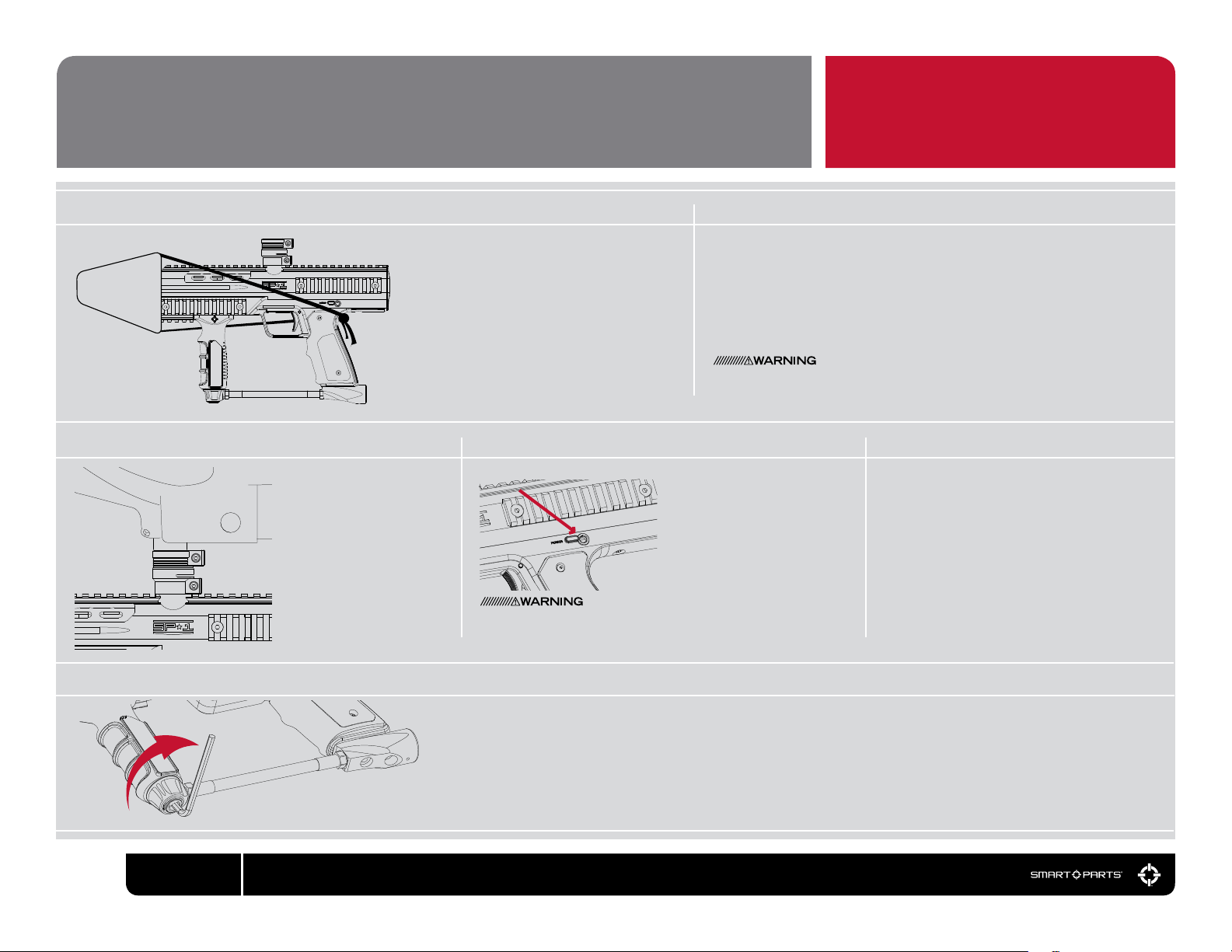
SETUP
BARREL BLOCKER PROPELLANT GAS
01 02
Screw the included barrel into the SP-1. Slide
the included barrel blocker over the barrel
and secure its cord as far back on the SP-1
body as possible, cinching it tight. The barrel
blocker is a critical piece of paintball safety
equipment – nearly as important as paintball
goggles. The barrel blocker must be fully
seated on the marker’s muzzle and secured
in place with its strap any time the marker is
stored or handled in an area where people or
property are not properly protected by paint-
ball goggles or paintball eld netting.
LOADER TURN POWER ON TRIGGER ADJUSTMENT
03 04 05
While an un-powered hopper
will work, powered loaders
will provide better perfor-
mance, and minimize paint
breakage. Snap the SP-1’s
clamping feedneck over the
body’s feed port, narrow end
facing the marker. Insert the
loader’s feedneck into the
larger end. Align the loader,
and tighten both the top and
bottom sides of the clamping
feedneck with a 7/64-inch
allen wrench.
POWER BUTTON
Although the power button serves as the SP-1’s safety switch to
prevent accidental ring, it should never be relied upon in place of a
barrel blocker and proper paintball eye protection.
Turn the marker on by pressing
the power button, and holding
it in for a full second. When the
SP-1 turns on, the power button
will glow red. The SP-1 is turned
off by pressing and holding the
power button for two seconds. To
conserve battery power, the SP-1
will turn itself off if it is not red
for more than 30 minutes.
The SP-1 is compatible with both CO2 and high pressure compressed air (HPA.)
Screw-in style HPA systems and CO
Adapter (ASA) on the bottom of the SP-1 grip frame. For best performance with
CO
2, use an anti-siphon tank, or a regular tank with a remote hose. Screw the
tank in slowly so that its valve opens slowly, creating a gentle rise in pressure,
rather than a rapid pop. Note – CO
be lled before use. When using CO
released from the bottom of the regulator. This is the normal function of the relief
valve protecting your marker from liquid CO
Never use oil or any petroleum based cleaner or lubricant in an HPA system. Use only manufacturer recommended lubricants, and strictly follow the
manufacturer’s instructions.
PLEASE READ CAREFULLY
2 tanks are screwed into the Air System
2 and HPA tanks are sold empty, and must
2, you may notice occasional bursts of gas
2.
The length of the SP-1’s trigger pull is adjustable.
A 0.050-inch allen wrench can be used to adjust
the trigger’s post travel limit – how far back the
trigger can continue to move past the ring point
– with the adjustment screw located on the lower
portion of the trigger. A 1/8-inch allen wrench can
be used on the pre-travel adjuster screw, located
where the trigger guard meets the grip frame, to
adjust how far forward the trigger can move once
it is released.
ADJUST VELOCITY
06
Increasing Velocity.
02
800.922.2147 www.smartparts.com
Fill the hopper with paintballs and turn it on. While wearing ASTM compliant paintball goggles, in an area where all bystanders are
protected, remove the barrel blocker and re over a chronograph to measure the velocity. Using a 5/32-inch allen wrench on the
adjuster in the bottom of the vertical regulator, turn clockwise to increase velocity/pressure, and counter-clockwise to decrease.
Take three or four shots after every adjustment to allow the gas pressure inside the SP-1 to stabilize. Adjust until the marker is ring
consistently within the limits for the eld where you are playing (for safety reasons, never adjust the SP-1 to re at greater than 300
feet per second.)
Page 5
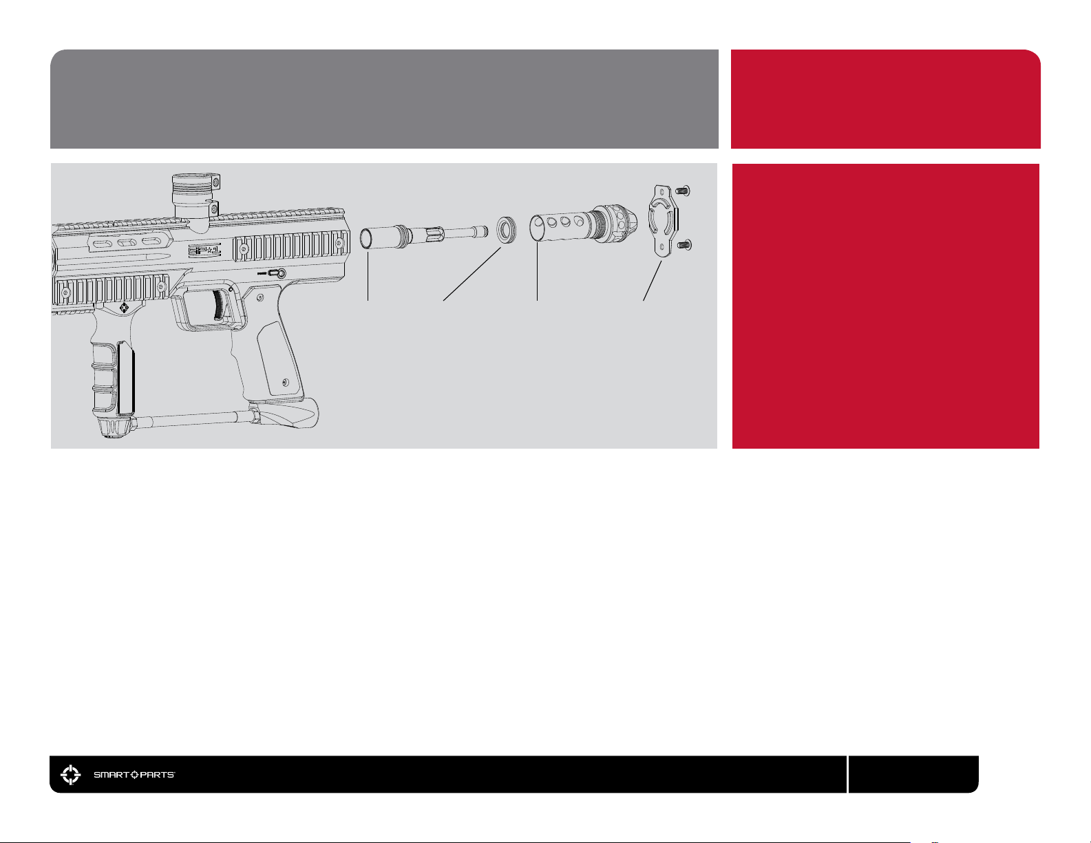
DISASSEMBLY/CLEANING
WET WEATHER NOTE:
PLAYING IN THE RAIN WILL NOT DAMAGE
YOUR SP-1, BUT YOU SHOULD NEVER
IMMERSE IT IN WATER. IF YOUR MARKER
SHOULD BECOME WATERLOGGED,
REMOVE THE BARREL AND RUBBER
BOLT BOLT STOP BOLT SLEEVE REAR COVER
The SP-1 valve system has only one major moving part, making it simple to maintain, but this does not mean maintenance can be ignored. The SP-1 should be
disassembled and cleaned any time it shows erratic performance, becomes contaminated with paint, dirt or other debris, or for general maintenance after 3 or 4
days of use.
GRIPS AND ALLOW THEM TO DRY OUT,
THEN FOLLOW THE DISASSEMBLY/
CLEANING INSTRUCTIONS.
PLEASE READ CAREFULLY
01 Unload and degas the SP-1. Remove the barrel and use a 1/8-inch allen wrench to remove the two rear cover screws from the back of the marker. Remove
the rear cover, then use a 5/16-inch allen wrench to unscrew and remove the bolt sleeve from the back of the SP-1.
02 Using a soft tool, like a wooden chopstick or plastic toothbrush, push the bolt and bolt stop out the back of the SP-1.
03 Clean the interior of the body, the bolt sleeve, bolt and bolt stop with a clean cloth or paper towel. Inspect their o-rings for signs of damage such as rips or
cuts and replace if necessary.
04 Lubricate o-rings with SL33K marker lubricant. Slide the bolt stop onto the bolt from the rear. Slide the rear of the bolt into the front of the bolt sleeve. Hold
this assembly vertically, with the front of the bolt pointing up, and insert it, upwards into the rear of the SP-1. Screw the bolt sleeve into place with
a 5/16-inch allen wrench – do not overtighten. Reinstall the rear cover and its screws.
This is all that is required for routine maintenance. Further disassembly of the SP-1 receiver and grip frame should be avoided unless necessary for repair, as it
may shorten the life of the marker. For additional information, please visit the support section at www.SmartParts.com
800.922.2147 www.smartparts.com
03
Page 6

UNLOADING/DEGASSING
Before storage, transport or maintenance, your marker will need to be unloaded and degassed. In an
area where it is safe to shoot and while wearing paintball goggles, loosen the SP-1’s clamping feedbeck
and remove the loader. By turning the marker upside down, you can empty any extra paintballs from the
feedneck into your hand. Remove the CO2 or HPA tank.
Although the power button serves as the SP-1’s safety switch to prevent accidental ring, it should never be
relied upon in place of a barrel blocker and proper paintball eye protection.
Turn on the marker and dry re in a safe direction until all of the gas pressure inside has been released. Turn
the SP-1 off by pressing and holding the power button for one second.
If the marker is not degassed, its regulator may hold enough pressure to re 3 or more shots, even if the gas
supply is removed.
TROUBLESHOOTING
SP-1 WILL NOT TURN ON
— Battery may be low or dead. Replace with a name brand 9-volt alkaline battery by removing the
rubber wraparound grip. Unplug the battery by carefully pulling away the battery clip – do not pull on
the battery clip wires.
SP-1 IS LEAKING OR SHOWS INCONSISTENT VELOCITY
— Disassemble and clean the bolt assembly. Inspect all o-rings and replace any that show signs of
wear or damage. Re-lubricate with SL33K and reassemble.
— Use a fresh 9-volt name-brand alkaline battery.
— If using CO
SP-1 IS LEAKING OR SHOWS INCONSISTENT ACCURACY
— This can be caused by poor quality, out of round paint. Use high-quality paintballs and store them in
a sealed container in a cool, dry place.
— Gas may occasionally vent near the bottom of the Max-Flo R vertical regulator. This is a normal
function as the regulator protects your marker and does not indicate a problem.
— Use a fresh 9-volt name-brand alkaline battery.
— If using CO2, an anti-siphon tank, or regular tank and remote hose will improve consistency.
SP-1 WILL TURN ON BUT WILL NOT FIRE
— Battery may be low. Replace with a name brand alkaline battery.
— CO2 or compressed air tank may be very low or empty – rell.
2, an anti-siphon tank, or regular tank and remote hose will improve consistency.
IMPORTANT
04
800.922.2147 www.smartparts.com
Page 7

WARRANTY
Smart Parts warrants for one (1) year to initial retail purchaser that the paintball marker and regulator are
free from defects in materials and workmanship. Disposable parts (batteries, o-rings, seals, springs, etc.)
are not warranted. The valve assembly is warranted for six (6) months. The solenoid and electronics on
the marker are warranted for six (6) months, plus an additional warranty of six months for electronic parts
only (installation and labor are not included.) This warranty does not cover surface damages (scratches
and nicks), misuse, improper disassembly and re-assembly, attempts made to drill holes or remove metal
from the external surfaces which could degrade performance and reduce pressure safety factors of the
marker. Do not make changes to the basic marker parts without written approval. The only authorized
lubricant for the marker is SL33K Lubricant. Use of any other lubricant could result in voiding your warranty.
Paintball markers are non-refundable. This warranty is limited to repair or replacement of defective parts
with the customer to pay shipping costs. This warranty is effective only if the customer returns the warranty
registration card enclosed with the marker. The warranty is non-transferrable. Do not attempt to alter the
trigger assembly in any way, as this will void your Smart Parts Inc. warranty. Trigger alteration of any kind
may result in serious injury. Replacement or alteration of the Max-Flo R Vertical regulator will void
warranty and may result in serious damage and or injury.
TECH SUPPORT
U.S. EAST COAST
Smart Parts, Inc.
100 Station Street
Loyalhanna, PA 15661
800.992.2147
U.S. WEST COAST
West Coast Repair Center
27326 Jefferson Ave #2
Temecula, CA 92590
951.296.1000
U.K.
Unit A6
Larkeld Trading Estate
New Hythe Lane
Aylesford,Kent
ME20 65W
++40 (0) 1622.719.995
Additional support and downloadable
product manuals are available through our
web site, www.smartparts.com.
800.922.2147 www.smartparts.com
05
Page 8

800.922.2147 100 Station St. Loyalhanna, PA 15661 www.smartparts.com manual version Web.01
 Loading...