

Page 1

eXTCy
Operation and adjustment instructions
TM
Page 2

Page 3

QUICK START
BARREL BARREL BLOCKER FILL TANK
01 02
03
Unpack the eXTCyTM and its barrel. Screw the barrel into the front of
the marker, hand tight. Take care not to strip the barrel threads or overtighten.
Put the supplied barrel
blocker over the end of the
barrel, securing its cord as far
back on the eXTCy
possible, and cinching it tight.
LOADER TURN ON GAS TURN ON THE eXTCyTM
04 05 06
ADJUST VELOCITY
07
Fit a paintball loader into the feedneck
of the eXTCy
wrench to lock the loader in place.
Powered force-feed loaders are
recommended, as the eXTCy
little recoil, and can easily outpace an
unpowered or agitating loader.
TM
. Use a 7/64-inch allen
TM
has
TM
body as
Gently gas up the eXTCy
slowly turning on the air system
(if HPA system has its own on/
off valve) or turning the bottom-
line ASA knob clockwise.
A gentle rise in pressure is
important, as a sudden blast
may reduce the service life
of the eXTCy
components.
TM
®
’s internal
by
Have your compressed air
(HPA) or CO2 tank lled by
a person who is properly
trained to do so. If using an
HPA system with an on/off
valve, make sure it is in the
OFF position. If using a CO2
tank or screw-in style preset
HPA system, ll it while it is
removed from the marker.
TM
Turn on the eXTCy
pressing the power button
momentarily. If the eXTCyTM
does not start, see the battery
section of this manual.
Although the power button
serves as the eXTCy
switch to prevent accidental
ring, it should never be relied
upon in place of a barrel blocker
and proper eye protection.
by
TM
’s safety
Fill the loader with paintballs. If it is a powered loader, turn it on. While wearing ASTM compliant paintball goggles, in an area where all bystanders are protected, remove the barrel
blocker and re over a chronograph to measure the velocity. Using a 5/32-inch allen wrench on the adjuster in the bottom of the vertical regulator, turn clockwise to increase the
velocity/pressure, and counter-clockwise to decrease. Take three or four shots after every adjustment to allow the gas pressure inside the eXTCy
is ring consistently within the limits for the eld where you are playing (for safety reasons, never adjust the eXTCy
modes of re are allowed at the eld where you are playing (semi-automatic, rebound, etc.) you may need to adjust the eXTCy
for more information.
TM
to re at greater than 300 feet per second). Depending on what
TM
’s ring mode. See the Electronic Adjustment section
GOGpaintball.com
TM
to stabilize. Adjust until the marker
00
Page 4

TABLE OF CONTENTS
Quick Start
Table of Contents and Safety Warnings
Getting Familiar
Barrel Blocker / Hopper
Gasses
Battery
Paint / Velocity
VisionTM Operation
Electronic Adjustment
Trigger Adjustment
Unloading / De-Gassing
Field Stripping
VisionTM / Detent Cleaning
Advanced Maintenance
GripFrame / Body Separation
Circuit Board Removal
Breech Removal
Vertical Regulator
Troubleshooting / Warranty
Parts Diagrams
00
01
02
03
04
06
07
08
09
13
14
15
16
17
18
19
20
22
25
• THE eXTCyTM IS NOT A TOY.
• MISUSE OF THE eXTCy
INJURY OR DEATH.
• EYE PROTECTION DESIGNED FOR PAINTBALL USE
MUST BE WORN BY THE USER AND ANY PERSON
WITHIN RANGE OF THE eXTCy
• GOG PAINTBALL® RECOMMENDS THAT T H E
eXTCyTM ONLY BE SOLD TO PERSONS 18 AND
OLDER.
• THOROUGHLY READ THE eXTCyTM OPERATION
AND INSTRUCTION MANUAL BEFORE OPERATING.
• TREAT EVERY PAINTBALL MARKER AS IF IT WERE
LOADED.
• NEVER LOOK DOWN THE BARREL OF A PAINTBALL
MARKER.
• KEEP YOUR FINGER OFF THE TRIGGER UNTIL
READY TO SHOOT. NEVER POINT THE eXTCyTM AT
ANYTHING YOU DON’T INTEND TO SHOOT.
• KEEP THE eXTCyTM ON SAFE (POWER OFF) UNTIL
READY TO SHOOT (SEE QUICK START).
• KEEP THE BARREL BLOCKING DEVICE ON THE
eXTCyTM’S MUZZLE WHEN NOT SHOOTING (SEE
BARREL BLOCKER SECTION).
• ALWAYS REMOVE PAINTBALLS AND DE-GAS THE
eXTCyTM BEFORE DISASSEMBLY (SEE DE-GASSING
SECTION).
• STORE AND TRANSPORT THE eXTCyTM UNLOADED
AND DEGASSED IN A SECURE PLACE.
• FOLLOW ALL MANUFACTURER’S WARNINGS
AND INSTRUCTIONS FOR PROPELLANT SOURCE
HANDLING, STORAGE AND FILLING.
• DO NOT SHOOT FRAGILE OBJECTS SUCH AS
WINDOWS.
• ALWAYS MEASURE THE VELOCITY OF PAINTBALLS
FIRED BY THE eXTCyTM BEFORE USE, AND NEVER
ADJUST TO FIRE ABOVE 300FPS (91.44M/S).
TM
MAY RESULT IN SERIOUS
TM
.
GOGpaintball.com
01
Page 5

GETTING FAMILIAR
PLEASE READ CAREFULLY
STATISTICS
WEIGHT:
OPERATING PRESSURE:
POWER SOURCE:
PROPELLANT:
RATE OF FIRE:
OPERATION:
MODES OF FIRE:
ANTI CHOP SYSTEM:
BARREL THREAD:
LUBRICANT:
1.85 lb
160 psi
9-volt Alkaline Battery
CO2 or Nitrogen/Compressed air
Uncapped Semi-Automatic - up to 20bps ramping / auto
Low pressure electropneumatic
12 modes incl: Semi, PSP, NPPL and Millennium
VisionTM Break-Beam eyes
®
GOG
For proper and consistent operation, the eXTCyTM should
only be lubricated with GR33SETM lubricating grease.
REQUIRED ITEMS FOR USE
• 5/32-inch Allen Wrench (included) - Velocity Adjustment
• Chronograph (provided for use at commercial paintball
eld) - Velocity Adjustment
• Barrel Blocker (included)
• CO2 or HPA tank (purchase seperately)
• ASTM Compliant Paintball Goggles with Mask
(purchase seperately)
• 68 Caliber Paintballs
• Paintball Hopper/Loader (purchase seperately)
• 9-Volt Alkaline Battery
REQUIRED ITEMS FOR MAINTENANCE
• 0.050-inch Allen Wrench (included) Trigger Adjustment /
TM
Vision
Eye Covers
• 5/64-inch Allen Wrench (included) - Battery Change
• 7/64-inch Allen Wrench (included)- Clamping Feedneck
• 1/8-inch Allen Wrench (included) - Stock/Backplate, Trigger
Adjustment, ASA, Grip, Breech and Circuit Board Screws
• 5/32-inch Allen Wrench (included) - Velocity Adjustment
• 5/16-inch Allen Wrench (included) - Bolt Sleeve
• Snap-Ring Pliers (purchase seperately) - Regulator
Disassembly (Advanced Maintenance)
TM
• GR33SE
Lubricant
(purchase seperately) - Paintball Marker
MAINTENANCE
The eXTCyTM has been designed with
simplicity in mind so that you can
concentrate on your game instead of your
marker. It has only one major moving part in
its valve system, with a minimal number of
seals. This DOES NOT mean that you should
neglect your eXTCyTM. If you take care of
it off the eld, your eXTCyTM will take care
of you on the eld. For best performance,
clean and grease your eXTCyTM frequently.
Many players disassemble and clean their
eXTCyTM after every day of use. While this
may seem a bit extreme, being vigilant in the
upkeep of your eXTCyTM will extend its useful
life considerably, and catch any problems
when there is time to correct them before
the next game. Playing in the rain will not
damage your eXTCyTM. In fact, the eXTCyTM.
has been tested and proven to function
underwater. However, long-term exposure
to moisture can cause rust damage to
some of the eXTCyTM’s screws, so if your
eXTCyTM should become waterlogged,
remove the barrel, stock, eye covers and
rubber grips and allow it to dry out, then
follow the disassembly instructions for full
cleaning. Clean out mud and paint with
a damp cloth and alcohol. Lubricate the
eXTCyTM ONLY with GR33SETM pneumatic
grease. Use fresh, high quality paintballs for
best performance.
GOGpaintball.com
02
Page 6

BARREL BLOCKER/HOPPER
PLEASE READ CAREFULLY
BARREL BLOCKER
The Barrel Blocking Device is a critical piece of paintball safety equipment - nearly as important as
paintball goggles. The Barrel Blocker serves to protect against accidental discharge of a paintball by
catching it before it can cause harm. A Barrel Blocker is included with the eXTCyTM and must be used
every time it is handled in an area where people or property are not properly protected by paintball
goggles or paintball eld netting. To use the Barrel Blocker simply slip it over the end of the barrel
and stretch its cord back over the back of the eXTCyTM or the rearmost part over which it can be
securely looped. Use the strap’s adjuster to cinch the strap tight, so that the Barrel Blocker can provide
protection against accidental discharge of a paintball.
The Barrel Blocker should only be removed when the eXTCyTM is on a “live” paintball eld and all
persons involved are wearing proper paintball protection.
HOPPER
The eXTCyTM is a high performance tournament grade paintball marker. Its low-force bolt and VisionTM
anti-chop system will prevent paintballs from being chopped if the hopper is not able to load paintballs
as fast as the eXTCyTM is being red. If you want to realize the eXTCyTM’s maximum repower potential,
you will need to use a high performance loader. High performance loaders, especially those which
provide force-feeding, will yield the best results with the eXTCyTM.
The eXTCyTM is equipped with a clamping feedneck that allows it to adapt to the small size differences
in hopper neck sizes, yet lock or release quickly. Using a 7/64-inch allen wrench, loosen the clamping
feedneck before installing a hopper.
FIG. 1
FIG. 2
BARREL BLOCKER IN USE
USE HIGH PERFORMANCE LOADER
GOGpaintball.com
03
Page 7

GASES
NEVER PUT OIL IN A COMPRESSED AIR REGULATOR OR
TANK - ONLY APPLY MANUFACTURER RECOMMENDED
LUBRICANTS.
COMPRESSED AIR
TM
The eXTCy
is a low-pressure paintgun. It operates at approximately 160 psi, which means it is capable of
functioning well with either high-pressure compressed air or CO2 as a power source. Proper set up of your
gas system will help you obtain the best possible performance from your eXTCyTM.
Whether using compressed air or CO2 it is important that the eXTCyTM is not exposed to sudden “pops”
of pressure. Always turn-on or screw-in a compressed air system or CO2 slowly, so that the valve opens
slowly and the gas pressure inside the marker is raised smoothly. Be gentle to the internals of your
eXTCyTM and they will reward you with a long service life.
High Pressure Air systems (HPA) are the preferred power source used in paintball and with the eXTCy
TM
because they are unaffected by temperature uctuations and do not have the potential for liquid
problems. HPA systems consist of a tank and a regulator, and are typically rated to store air or nitrogen
at pressures of 3,000 or 4,500 psi. Although pure nitrogen is almost never used in paintball, many players
call compressed air “nitro” as air is made up of more than 70% nitrogen, allowing the two gasses to be
used interchangeably in paintball equipment.
The eXTCy
TM
is congured for use with screw-in style HPA systems. Although HPA systems pre-set to
deliver approximatly 400 psi (low output) will work with the eXTCyTM, 800 psi (high output) systems are
preferred, to reduce the risk of gas starvation under rapid re.
Never use oil or any petroleum based cleaner or lubricant in a compressed air regulator or tank. Exposure to
pressurized air increases oil’s ammability and can cause a serious safety hazard. Only use manufacturer
recommended lubricants with compressed air systems, and follow the manufacturer’s maintenance and
operation instructions explicitly.
If you are using your eXTCyTM with an adjustable output compressed air system, it should be set to deliver
about 800 psi. The eXTCyTM’s vertical regulator can accommodate a wide range of input pressures, so
exact adjustment of the air system is not critical.
NOTICE
Due to shipping restrictions, CO2 and HPA tanks are sold empty. They must be lled before they can be
used. Most paintball shops and elds are equipped to ll HPA tanks. Paintball shops, elds, many hardware
stores and sporting goods stores will have the equipment and trained personnel to ll paintball CO2 tanks.
FIG. 3
HPA TANK BEING FILLED
NOTICE
TM
The eXTCy
is factory congured for use with
CO2. Its dwell setting must be changed to obtain
optimum performance with HPA. See the Firing
Modes / Dwell section of this manual to learn how.
NOTICE
Although the eXTCyTM can be powered by
compressed air, typical home, garage or industrial
air compressors cannot provide the high pressures
required to ll a paintball HPA tank. Paintball HPA
systems can be relled by paintball elds and
stores which use higher pressure compressors
similar to those used in the SCUBA and reghting
industries.
GOGpaintball.com
04
Page 8

GASES
PLEASE READ CAREFULLY
USING CO
CO2 is usually not recommended for electronic paintball markers. This is not the case, however with
the eXTCyTM. The eXTCyTM can function extremely well with CO2 as a power source, but doing so does
require the correct conguration. The use of CO2 will not damage the seals in the eXTCyTM, freeze or
cause damage to its circuit board.
The important thing to remember if using CO2 is that best performance can be achieved when only
gasseous CO2 is fed to the eXTCyTM, and liquid CO2 remains in the tank.
Although the relief valve integrated into the eXTCyTM’s vertical regulator provides the marker with
protection from pressure spikes, those pressure uctuations can cause poor performance, and
temporary blockage of the eXTCyTM’s solenoid valve.
The bottom-line ASA tting on the eXTCyTM places the CO2 level, like in Figure 5. When the marker is
held in typical ring positions the liquid CO2 will pass through the valve into the marker unless an anti-
siphon system is used.
Anti-siphon CO2 tanks contain a J-shaped tube that draws gaseous CO2 from the top of the tank
when it is in a horizontal position. Anti-siphon tubes must be professionally installed, to ensure that
critical safety checks are performed during valve installation. Anti-siphon CO2 tanks should not be
used with remote hoses.
Alternative CO2 arrangements include placing the CO2 tank vertically in a pack, and using a paintball
remote hose to feed CO2 to the eXTCyTM. This arrangement not only prevents liquid CO2 from entering
the marker, but also makes the marker assembly lighter weight. Another possible conguration is to
use a third-party ASA or ASA mounting adapter which mounts a standard CO2 tank at an angle like in
Figure 4. In this arrangement gravity keeps the liquid CO2 below the valve neck.
BOTTOM-LINE ASA
2
FIG. 4
FIG. 5
IMPORTANT
CO2 may also be congured with a remote
hose with-out Anti-Siphon. [Not Shown]
ANGLED CO2 [CUTAWAY VIEW]
CO2 WITH ANTI-SIPHON [CUTAWAY VIEW]
The bottom-line ASA tting on the eXTCyTM can be removed by unscrewing the two industry-standard
10-32 mount screws holding it to the grip frame after unscrewing and removing its on/off knob. If
replacing the ASA, be sure the model chosen takes into account the type of gas system being used
(horizontal for anti-siphon CO2 tanks or compressed air, angled for standard CO2 tanks).
GOGpaintball.com
05
Page 9

BATTERY
OVER TIME BATTERIES MAY LEAK. ALWAYS REMOVE THE
BATTERY FROM THE eXTCy
MORE THAN A MONTH.
TM
WHEN STORING FOR FOR
BATTERY
TM
The eXTCy
consistently deliver the amperage needed to operate the eXTCy
is powered by a standard 9-volt alkaline battery. Lower cost “heavy duty” batteries will not
TM
reliably. Erratic performance, especially
drops in velocity or skipped shots during rapid re can result from a battery that is not delivering full
power.
The eXTCyTM is also compatible with 9-volt rechargeable batteries. Because specications of batteries
vary widely from brand to brand, use of any rechargeable battery will require testing to determine if it
can power the eXTCyTM reliably and t correctly in the grip frame. Some NiCD “9v” rechargable batteries
actually operate at 7.2 volts. These types of batteries will not work well with the eXTCyTM.
Each time the eXTCyTM is turned on, the power button LED will blink 5 times rapidly, with its color indicating
the estimated charge level of the battery. Green indicates a charge level between 75% and 100%. Yellow
denotes a charge level between 50% and 75%, while red ashing indicates that the remaining charge is
estimated to be below 50%. It is important to note that different types and even brands of rechargeable
batteries will give different readings than alkaline batteries., so experience will be the best teacher as to
how much remaining use to expect once a reduced charge level is indicated.
Any time the eXTCyTM exhibits erratic performance, drops velocity or skips shots while rapid ring, does
not shoot or does not turn on, the rst step in troubleshooting should always be to replace the battery with
a brand-new, name-brand alkaline battery.
To replace the eXTCyTM battery, use a 5/64-inch allen wrench to remove the two screws from the left side
of the rubber grip, then open the grip. Be careful opening the grip from the grip frame. Folding the grip
back around the trigger frame may seem convenient, but may cause tearing or stretching in the center of
the grip, which will cause it to pucker or t poorly when reinstalled. As an alternative to folding the grip
open, simply remove it entirely by removing the two grip screws from its right side.
FIG. 6
ALKALINE BATTERY
Remove the old battery, taking care not to bend, kink or strain its wires. Unsnap the battery from its
connector by pulling on the connector, not the wires. Snap in a fresh battery, then place that in the grip
frame, tucking the wires into place, before closing and re-securing the grip. The battery and connector
should t snugly in the battery space, so that they do not shift around during use. Some off-brand batteries
may be too large to t correctly in the grip frame. If this is the case, do not force the battery into position,
instead replace it with a name-brand alkaline battery.
GOGpaintball.com
06
Page 10

Page 11

TM
VISION OPERATION
VISION BYPASS
The eXTCyTM is equipped with a VisionTM break-beam anti-chop system, allowing it to acheive the
highest possible rates of re without chopping or mis-feeding paintballs.
The eXTCyTM circuit board is linked to a light emitting diode and detector installed in the marker’s
breech. When a paintball drops down the feedneck into the breech, it breaks the light beam and
the eXTCyTM circuit board detects its presence. When the VisionTM system is activated, the eXTCyTM
will not re until it “sees” a paintball in the breech. This prevents the marker from dry ring or from
chopping a paintball in half by ring before the ball is completely loaded.
There may be times when it is desirable to bypass the VisionTM system, such as dry-ring the eXTCyTM
to test electronic adjustments, or when de-gassing.
While the eXTCyTM is turned on, pressing and holding the power button for approximately one-half
second will turn the VisionTM system off, allowing the marker to re whenever the trigger is pulled,
whether or not there is a paintball in the breech. Pressing for approximately a half second will also turn
VisionTM back on.
When VisionTM is on, the power button will glow green. When it is off, the button will glow red.
FIG. 8
VISIONTM DE-ACTIVATION
GOGpaintball.com
08
Page 12

Page 13

Page 14
Page 15

ELECTRONIC ADJUSTMENT
Pulls To Enter: (Power Button LED blinks slowly red) - For Rebound
determines how many times the trigger must be pulled before marker ramps up to more than one shot
per trigger pull. Pulls to enter may be set between 1 and 5 pulls.
Enter Rate: (Power Button LED blinks slowly green) - For Rebound
how frequently the trigger must be pulled before the marker ramps up to more than one shot per trigger
pull. Enter rate may be set between 4 and 12 trigger pulls per second.
Sustain Rate: (Power Button LED blinks slowly yellow) - For Rebound
determines how frequently the trigger must be pulled to continue ramping more than one shot per
trigger pull after ramping has begun. Sustain Rate may be set between 1 and 10 trigger pulls per
second.
FSDO Compensation: (Power Button LED blinks slowly red and green) - When a marker rests, its bolt
may stick in position and cause a low-velocity shot the next time it is red. This is known as First Shot
Drop-Off, or FSDO. FSDO Compensation increases the dwell time of the rst shot of a group, providing
additional time to break friction between the breech and the bolt’s o-rings before the bolt moves
forward. FSDO Compensation may be adjusted from zero (off) to 15 milliseconds in 1 millisecond
increments. When the marker rests for 20 seconds or more, the next shot red will have the FSDO
Compensation value added to its dwell time. The default FSDO setting is 20 milliseconds.
TM
Vision
compatibility between the eXTCyTM circuit board and other markers. By default this setting will be 1, for
use with the eXTCyTM’s wired VisionTM eyes. A setting of 2 would be used for compatibility with circuit
board style VisionTM eyes, such as those used for upgrade on the G-1TM and eNVyTM.
Hardware: (Power Button LED blinks slowly yellow and green) - This setting provides
TM
Mode, the Pulls To Enter
TM
Mode, the Enter Rate determines
TM
Mode, the Sustain Rate
GOGpaintball.com
12
Page 16
TRIGGER ADJUSTMENT
IMPORTANT
THE TRIGGER MUST COME TO A STOP WITH ITS
ADJUSTMENT SCREW AGAINST THE GRIP FRAME OR
DAMAGE TO THE CIRCUIT BOARD AND OR TRIGGER
SWITCH MAY OCCUR.
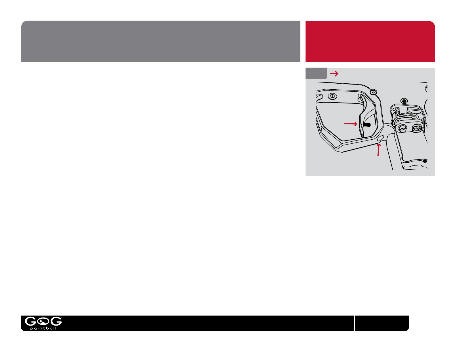
The length of the eXTCyTM trigger pull is fully adjustable.
A setscrew in the lower half of the trigger sets the post-travel adjustment, or how far back the trigger
can be pulled. Turning the screw clockwise with a 0.05-inch allen wrench will shorten the trigger
pull. Turning counter-clockwise will increase it. When setting post-travel limit, it is important that the
trigger pull is not set so short that the trigger does not activate the microswitch on the eXTCyTM’s
circuit board, as this would leave the marker unable to re. Similarly, the post-travel adjustment screw
must butt up against the trigger frame when the trigger is pulled. If the post-travel screw is underadjusted the trigger will stop against the microswitch inside the marker, instead of on the screw. This
situation can cause damage to the microswitch and or circuit board when the trigger is pulled hard.
The forward limit of the trigger’s movement, or pre-travel is adjusted by the use of a 1/8-inch allen
wrench. The pre-travel trigger adjustment screw is located at the bottom of the trigger guard where it
meets the grip frame. It may be helpful to remove the marker’s rubber grips to provide easier access
when making adjustments. As when changing the battery, it is better to completely remove the rubber
grip than to only open one side and fold it past the trigger guard. Turning the pre-travel adjustment
screw clockwise decreases how far forward the trigger can move, while turning counterclockwise
increases. If the trigger is not adjusted to swing far enough forward when released, the microswitch
inside the eXTCyTM will not be able to reset, resulting in the marker not ring.
Always check the trigger after making adjustments. Be sure that the trigger switch clicks when the
trigger is pulled, and again when it is released. Also make sure that when the trigger is pulled it is
being stopped by the post-travel adjustment screw, not by pressing up against the microswitch
inside the marker.
FIG. 9
TRIGGER ADJUSTMENT POINTS
POST-TRAVEL
PRE-TRAVEL
GOGpaintball.com
13
Page 17
UNLOADING/DE-GASSING
PLEASE READ CAREFULLY
At the end of each day’s use and before performing maintenance work on your eXTCyTM, it will
need to be de-gassed, and all paintballs must be removed.
In an area where it is safe to shoot (such as the chronograph area at a paintball eld) and while
wearing paintball goggles, remove the hopper from the eXTCyTM. By turning the eXTCyTM upside
down, you can empty any extra paintballs from the feedneck into your hand. Turn the eXTCyTM on.
Dry-re 2 or 3 shots in a safe direction to ensure that no paintballs remain in the eXTCyTM. In order
to dry-re the marker, the VisionTM anti-chop system must be turned off (see VisionTM operation) or
set to one of its delayed modes (see Electronic Adjustment).
Turn off the HPA system if it is equipped with its own on/off control, or turn off the HPA system or
CO2 tank by turning the bottom-line ASA control knob counter-clockwise. Dry re the eXTCyTM in
a safe direction until all of the gas pressure inside has been released. At this point the only sound
you should hear when you pull the trigger is the click of the solenoid valve. Often this sound will
be too quiet to hear. Turn off the eXTCyTM.
If using a CO2 tank or screw in HPA system, unscrew it from the bottom-line ASA.
EVEN WITH NO CO2 OR COMPRESSED
AIR SYSTEM ATTACHED, THE
EXTCYTM MAY STILL HAVE ENOUGH
GAS PRESSURE STORED IN THE
REGULATOR AND FIRE CHAMBER TO
FIRE 2 OR MORE SHOTS. YOU MUST
DE-GAS YOUR EXTCYTM BEFORE
PERFORMING ANY MAINTENANCE
PROCEDURES.
ALWAYS WATCH COMPRESSED GAS
CYLINDERS (CO2 OR HPA) TO MAKE
SURE THAT THE CYLINDER AND VALVE
ARE UNSCREWING FROM THE ASA,
AND THAT THE CYLINDER IS NOT
UNSCREWING FROM ITS VALVE. IF THE
CYLINDER DOES BEGIN TO SEPARATE
FROM ITS VALVE, STOP IMMEDIATELY,
AND SEEK PROFESSIONAL
ASSISTANCE.
GOGpaintball.com
14
Page 18
FIELD STRIPPING
The valve system in the eXTCyTM has only one major moving part. Regular cleaning and lubrication is necessary to ensure accurate and consistent performance. The eXTCyTM
should be eld stripped, cleaned and lubricated any time it shows erratic performance, becomes contaminated with paint, dirt or other debris, or for general maintenance after
3 or 4 days of use.
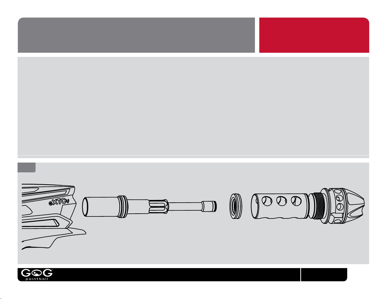
Unload and de-gas the eXTCyTM. Remove the barrel and use a 5/16-inch allen wrench to unscrew and remove the bolt sleeve from the back.
Using a soft, non-marring tool like a wooden chopstick or plastic toothbrush, push the bolt and bolt stop out the back of the eXTCyTM. Clean the interior of the receiver, the bolt
sleeve, bolt and bolt stop with a clean cloth or paper towel. Inspect their o-rings for signs of damage such as cuts or rips, and replace if necessary. Lightly lubricate all o-rings
with GR33SETM paintgun grease. Use GR33SETM sparingly, as over-lubrication can cause the eXTCyTM to operate inconsistently. Do not lubricate the rearmost o-ring on the bolt
sleeve, it provides friction to keep the bolt sleeve in place during operation.
Slide the bolt stop onto the bolt from the rear. Slide the rear of the bolt into the bolt sleeve. Hold this entire assembly vertically with the front of the bolt pointing upward, and
insert it up into the back of the eXTCyTM. Screw the bolt sleeve into the back of the eXTCyTM by hand, taking care not to cross-thread it into the receiver.
Use the long end of a 5/16-inch allen wrench to turn the bolt sleeve until it is snug. Take care not to over-tighten the bolt sleeve, it only needs to t snugly in place.
FIG. 10
CLEANING
BOLT BOLT STOP BOLT SLEEVE
GOGpaintball.com
15
Page 19
TM
VISION/DETENT CLEANING
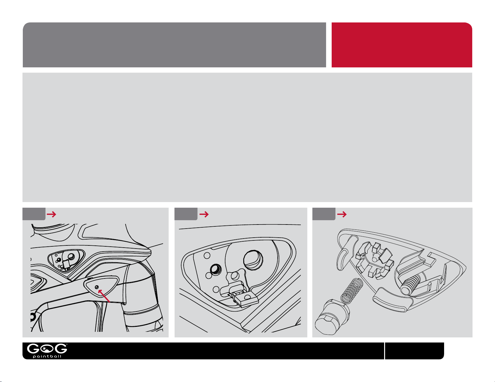
The VisionTM eye covers of the eXTCyTM are easily removed to provide access to both the VisionTM sensors and the marker’s ball-detents. To remove the eye covers, rst unload
and de-gas the marker following the instructions in this manual, then use a 0.050-inch allen wrench through the eye-cover access hole to unscrew the eye cover retaining screw,
then tilt the eXTCyTM to the side, and if necessary tap it lightly against one hand to work the eye cover out.
With the eye cover removed, an o-ring pick can be used to pry the VisionTM LED or detector out of its pocket by one of its top corners. Care must be taken not to scratch the
dome shaped lens molded into the body of the eye. With the eye gently folded out of the way, the eye, eye pocket and ball detent opening in the breech may all be thoroughly
cleaned with a cotton swab.
If the ball detent is worn to the point that it does not protrude slightly into the breech, or dirty to the point that it does not spring easily in or out, it may be removed from the eye
cover for cleaning or replacement. To remove the ball detent, use an o-ring pick to carefully pry back the ball detent retaining ngers one at a time and work the detent out of the
eye cover. If the ball detent is excessively worn, it must be replaced for proper operation of the eXTCyTM. The ball detent spring may become bent or damaged during removal
of the ball detent. If this happens, it must be replaced. After cleaning or replacement, t the ball detent spring into the ball detent, set its other end on the spring guide in the eye
cover, then carefully work the detent past the detent retaining ngers. Note the alignment of the ball detent for a proper t, its wider at edges should be at the top and bottom.
When re-installing the eye cover, use the long end of the allen wrench to tighten the eye cover retaining screw. Take care not to cross-thread the eye cover retaining screw, or
tighten it beyond a snug t, these can cause permanent, non-repairable damage to the breech.
CLEANING
FIG. 11
EYE COVER REMOVAL EYE CLEANING BALL DETENT REMOVAL
FIG. 12 FIG. 13
GOGpaintball.com
16
Page 20
ADVANCED MAINTENANCE
NOTE: Unload and degas the eXTCy
any cleaning or maintenance work.
TM
before
The internal gas lines and electronic components of the eXTCyTM are well protected inside its body – however they are delicate and may be damaged by improper handling
or re-installation. For this reason it is highly recommended that full disassembly of the eXTCy
only when necessary to x a problem or install an upgrade. Removal of internal hoses from their barbed ttings will stretch them to the point that they cannot be re-used
without causing leaks. In other words, if it ain’t broke, don’t x it.
Occasionally a more thorough disassembly of the eXTCy
damaged component or install an upgrade. These tasks require removal of the grip frame and or disassembly of the body.
Unload and degas the eXTCy
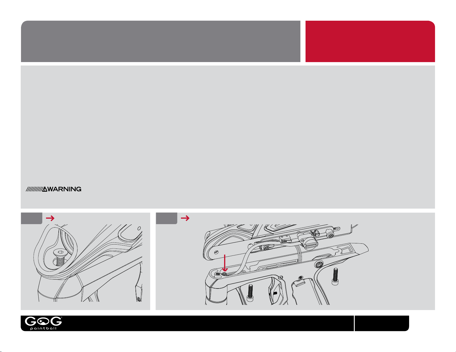
Using a 1/8-inch allen wrench, remove the breech screw from the front of the breech. Next remove the two grip frame screws securing the grip frame to the body. Carefully
slightly separate the grip frame from the receiver. Be aware that the clear power button can fall out of its position in the side of the grip frame. Be careful not to drop or lose
it. The body will still be connected to the grip frame by the hose running between the front of the grip frame and the solenoid valve on the circuit board.
Tilt the body slightly away from the grip frame and carefully use a 1/8-inch allen wrench to unscrew the barbed banjo tting which connects the gas supply hose to the grip
frame. Alternatively, the hose may be pulled off of the barb in the grip frame - doing so will require the hose to be replaced however, as its end will have been stretched by
the barbed tting and will no longer seal reliably.
Completely separate the body from the grip frame. Watch to make sure the battery clip does not snag in the grip frame as the two parts are separated.
Reassembly of the grip frame to the body is done in the reverse order, taking care not to allow the battery wires to or hoses to become pinched or entrapped while joining
the body to the grip frame. Use the long end of the allen wrench when reinstalling the banjo ttings and grip frame screws, to avoid over-tightneing.
Over-tightening or cross threading screws or ttings may result in permanent, nonrepairable damage to the breech.
FIG.14
BREECH SCREW REMOVAL
TM
, remove the barrel, rubber grip and battery, following the instructions in this manual. Similarly, eld strip the bolt/valve system.
TM
receiver is necessary to remove paint or debris that has worked between the breech and body shell, replace a
FIG. 15
GRIP FRAME REMOVAL
TM
be performed by an airsmith with GOG PaintballTM factory training, and then
GOGpaintball.com
17
Page 21
ADVANVED MAINTENANCE
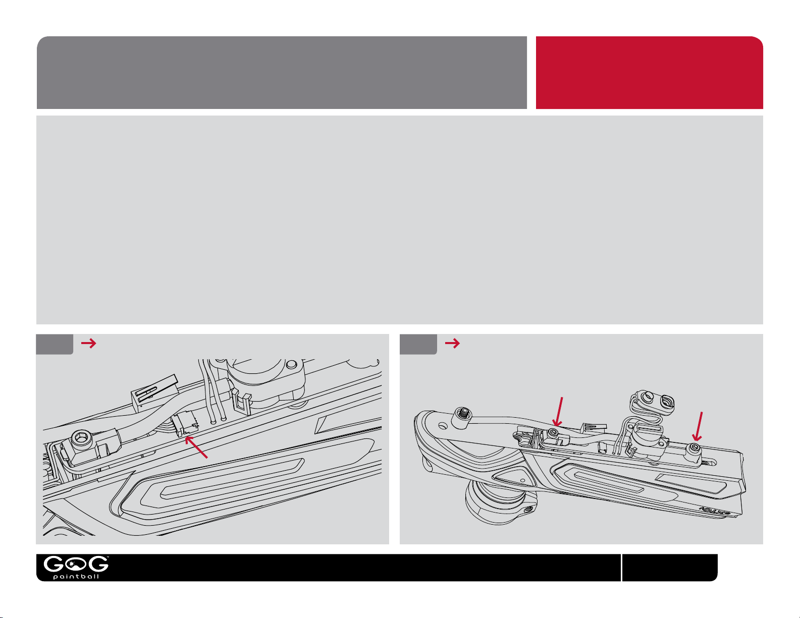
The circuit board is removed from the body by rst unplugging the VisionTM wiring harness from its socket. Take care to grasp the plug and remove it - do not pull by the
wires or they plug may be damaged.
Using a 1/8-inch allen wrench, unscrew the 2 banjo ttings which attach the circuit board to the body and breech.
The circuit board may then be carefully lifted away from the body and breech.
When re-attaching the circuit board to the body and breech, take extreme care not to cross thread the ttings. Use the long end of the allen wrench to tighten the gas ttings
and all screws, being careful to tighten them snug without over tightening. Over-tightening or cross threading screws or ttings may result in permanent, nonrepairable
damage to the breech.
Be sure to guide the battery clip down into the grip frame before re-joining the grip frame and receiver. Make sure the clear power button does not fall out of its place during
reassembly.
Be certain all wires and hoses are tucked into their places before rejoining the grip frame to the receiver. If the grip frame does not t snugly to the receiver do not force it.
Instead, pull the grip frame back away and look for hoses, wire, or improperly placed parts blocking the t.
CONTINUED
FIG. 16
UNPLUG VISIONTM WIRING
FIG. 17
UNSCREW BANJO FITTINGS
GOGpaintball.com
18
Page 22
ADVANVED MAINTENANCE
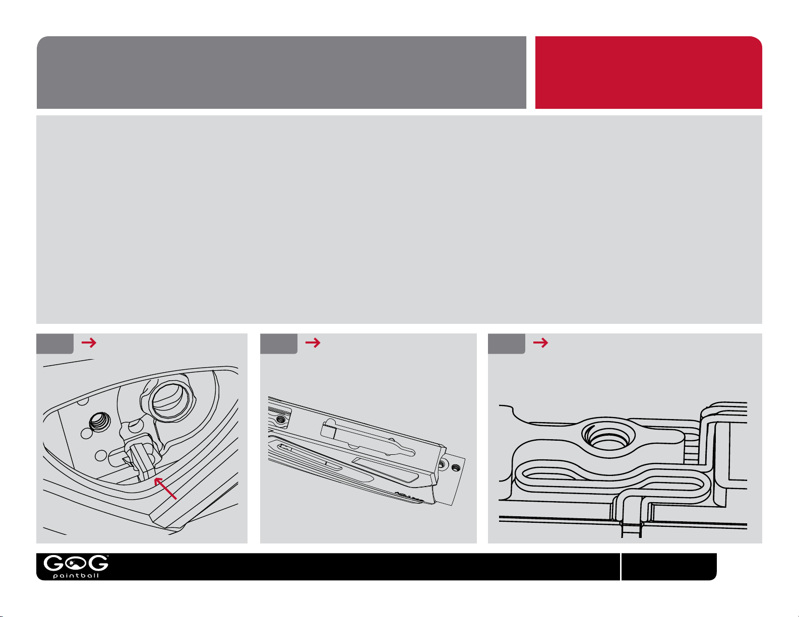
If removing the breech from the body cover, the VisionTM wiring harness must be removed rst. Uncoil the VisionTM wires and remove both eyes from their pockets (see
TM
Vision
shell, gently pulling its wires ahead of it so they do not bind.
Slide the breech out the back of the body cover. Carefully clean any paint or debris from the breech and body cover
The circuit board may then be carefully lifted away from the body and breech.
After sliding the breech back into place, the Vision
into their pocket as shown before reinstalling the circuit board.
/detent cleaning). Carefully twist each eye so that its dome shaped lens faces forward and guide it down through the slot in the beech and out the bottom of the body
TM
wiring harness and eyes are reinstalled via the same openings through which they were removed. Coil the Vision
CONTINUED
TM
wires
FIG. 18
ROTATE AND REMOVE EYES
FIG. 19
SLIDE BREECH OUT BACK
FIG. 20
COILED VISIONTM WIRES
GOGpaintball.com
19
Page 23
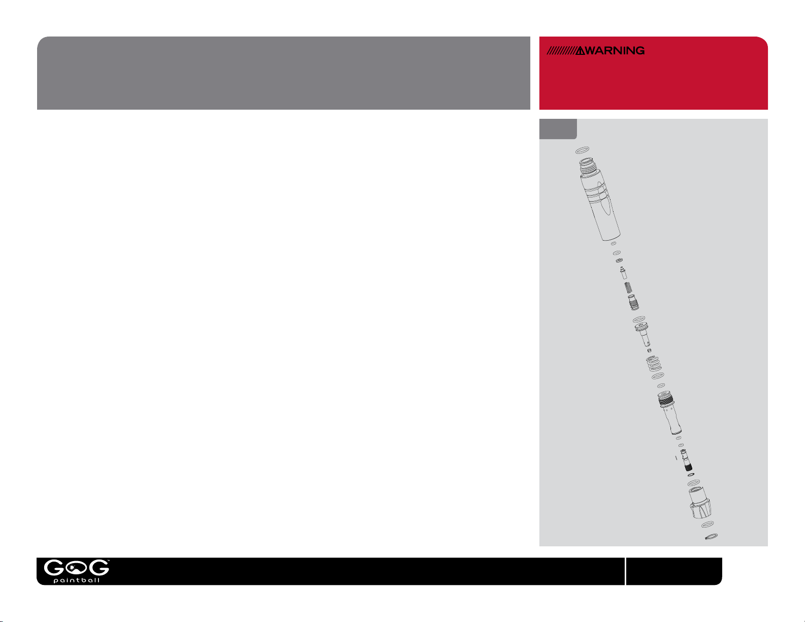
VERTICAL REGULATOR
SERVICE AND ADJUSTMENT TO THE REGULATOR WILL
CAUSE CHANGES IN VELOCITY. ALWAYS RE-CHRONOGRAPH
THE MARKER FOLLOWING THE PROCEDURE IN THIS MANUAL
AFTER WORKING WITH THE REGULATOR.
REGULATOR SERVICE
Although explained here, regulator service should only be performed by a GOG PaintballTM trained airsmith.
With the marker unloaded and de-gassed, unscrew the regulator from the marker and remove the grip
frame following the instructions in this manual. Take care not to lose the lter screen that sits inside the
vertical regulator’s ASA connection.
Using a pair of snap-ring pliers, remove the snap-ring from the bottom of the regulator and slide the
regulator off the swivel. This is the preferred way to separate the regulator from the hose and bottomline
ASA because it does not disturb the sealed hose ttings and is not likely to cause a leak.
Using a 7/16 open end or adjustable wrench, engange the wrench ats in the sides of the spring platform
and remove it from the bottom of the regulator body. The regulator spring will now be free to fall out into
your hand. The brass regulator piston may be removed by tapping the regulator body against a table top
or solid, but soft surface such as a block of wood.
At this level of disassembly, the seal in the end of the piston and the regulator body may be inspected,
cleaned with a soft cloth or cotton swab, and replaced if necessary. If the regulator seal shows signs of
damage, it may be removed and ipped over so that its back side is used instead. If both sides of the seal
are damaged, it must be replaced. Lightly lubricate all o-rings with GR33SETM for reassembly.
Do not lubricate the regulator seal at the end of the piston.
FIG. 21
REGULATOR DISASSEMBLY
GOGpaintball.com
20
Page 24

VERTICAL REGULATOR
[ CONTINUED ]
REGULATOR SERVICE, CONTINUED
The relief valve assembly should only be removed if it is constantly leaking. Occasional venting, especially
if using CO2, is normal and does not indicate a malfunction. The relief valve assembly may be removed
with a 5/32-inch allen wrench.
The velocity adjuster is located inside the lower end of the spring platform and similarly should only be
removed if shown to be the source of a leak or clog. First the internal c-clip ring must be removed from
inside the spring platform. This must be done with a pair of narrow snap-ring pliers. Some airsmiths have
used bench grinders to re-shape standard snap-ring pliers for this task. The adjuster is equipped with
left-hand threads and will need to be turned clockwise for removal. If regulator blockage is suspected, be
sure to inspect, and if necessary replace the inlet lter in the side of the velocity adjuster.
The vertical regulator is reassembled in the reverse order of disassembly. The piston slides into the
regulator body wide end rst, followed by the regulator spring. The spring platform should be tightened
for a snug t. Do not over-tighten. Re-attach the regulator swivel to the bottom end of the regulator and
secure it in place with its snap-ring. Reinstall the assembled regulator into the marker. Re-adjust velocity
after servicing the regulator.
NOTICE
THE RELIEF VALVE IN THE VERTICAL
REGULATOR PROVIDES PROTECTION
AGAINST PRESSURE SPIKES CAUSED
BY SEAL FAILURE OR LIQUID CO2.
REPLACING THE VERTICAL REGULATOR
WITH ANY OTHER BRAND OR MODEL
WILL BY-PASS AN IMPORTANT SAFETY
FEATURE CREATING A RISK OF
EQUIPMENT FAILURE OR INJURY AND
INVALIDATING THE GOG PAINTBALLTM
WARRANTY.
GOGpaintball.com
21
Page 25
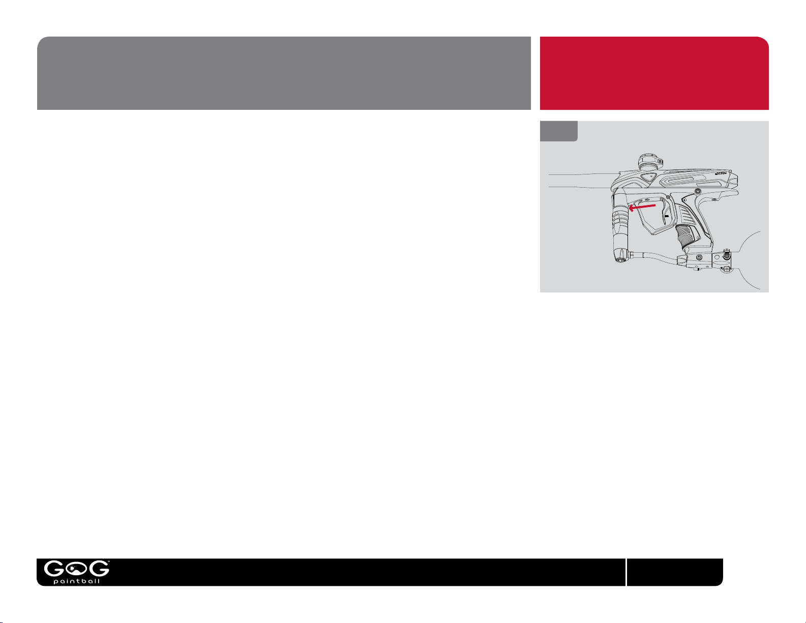
TROUBLESHOOTING
IMPORTANT
MARKER IS LEAKING INTERNALLY
• Liquid CO
normal, and does not require repair. If CO
is properly congured to prevent feeding of liquid CO
may cause temporary venting from relief valve or solenoid valve. This is
2
is venting frequently, make sure the marker
2
.
2
• Pneumatic hoses may be loose, damaged or not fully connected. Replace hoses with
TM
genuine GOG Paintball
• Hose has been disconnected and re-attached. Replace with a new GOG Paintball
hoses only.
TM
internal hose. Removing a hose streches it so that it cannot be re-used without leaking.
MARKER IS LEAKING DOWN THE BARREL
• One or more of the bolt or bolt stop o-rings are damaged or dirty. Inspect and replace
if necessary, making sure to clean and lubricate the parts following the instructions in
this manual.
MARKER IS LEAKING FROM BOTTOMLINE ASA
• Unload and de-gas the marker. Inspect the CO
TM
lubricate with GR33SE
and if necessary replace.
or HPA tank o-ring. Clean, lightly
2
MARKER IS OCCASIONALLY LEAKING FROM THE VERTICAL REGULATOR
• Gas may occasionally vent near the top of the vertical regulator (see Fig. 21) especially
when using CO
and does not indicate a problem. If CO
properly congured to prevent feeding of liquid CO
. This is a normal function of the relief valve protecting the marker,
2
is venting frequently, make sure the marker is
2
.
2
FIG. 21
RELIEF VENT
GOGpaintball.com
22
Page 26

TROUBLESHOOTING
MARKER EXHIBITS FIRST SHOT DROP-OFF (FSDO)
• FSDO is a low velocity, or non-ring rst shot, followed by normal shooting and is often
caused by debris in the bolt or a poorly lubricated bolt. Clean the bolt, breech, bolt stop
and bolt sleeve, and lubricate them with GR33SE
section of this manual.
• FSDO can be caused by dwell and or FSDO Compensation settings that are too low
for the marker’s gas supply and conguration. Follow the directions in the Electronic
Adjustment section of this manual and set the dwell to the minimum recommended setting
for the marker’s gas supply and conguration or higher, and the FSDO Compensation
setting to the default value or higher.
MARKER EXHIBITS INCONSISTENT VELOCITY OR DROPS OFF SIGNIFICANTLY
DURING RAPID FIRING
• Check paint quality. Your marker is optimized for use with fresh, high-quality paintballs.
Paintballs of inconsistent quality, or paintballs that have been exposed to humidity or
temperature extremes may vary in size or roundness causing inconsistent operation.
• Gas pressure could be low. Fill gas source and make sure gas supply is turned on.
• Battery may be low. This will be most noticeable with velocity dropping and then entire
shots not ring during rapid re. Replace battery with a new name brand alkaline battery.
• Regulator may be contaminated or damaged. Follow the instructions in this manual or
TM
see a GOG Paintball
• Liquid CO
may be entering the regulator – if using CO2, see the gasses section of this
2
manual for guidance in proper CO
technician for service.
set-up.
2
TM
as instructed in the Field Stripping
IMPORTANT
GOGpaintball.com
23
Page 27

TROUBLESHOOTING
MARKER WILL TURN ON BUT WILL NOT FIRE
• Battery may be low or dead – replace with fresh name brand alkaline battery.
• The forward trigger limit adjustment screw may be set in too far, preventing the trigger
from resetting. See the trigger adjustment section of this manual for guidance.
• The rear trigger limit adjustment screw may be set in too far, stopping the trigger before
it can re the marker. See the trigger adjustment section of this manual for guidance.
• Trigger switch may be damaged. Contact your dealer or GOG Paintball
support.
• Regulator output pressure may be too high. Adjust the velocity to its lowest limit, then
follow the velocity adjustment procedure in this manual.
• Liquid CO
guidance in proper CO
may be entering the valve – see the gasses section of this manual for
2
set-up.
2
MARKER IS BREAKING PAINT OR DOUBLE-FEEDING
• Use only fresh, high-quality paintballs. Poor quality paint, or paint damaged by humidity
or temperature extremes during shipping or storage, will nor perform well.
• Ball detents may be worn, dirty or damaged. Inspect, and if necessary, replace
following the instructions in this manual.
TM
• The Vision
anti-chop function may be turned off. Turn VisionTM on, following the
instructions in this manual.
TM
technical
IMPORTANT
TECH SUPPORT
Our Technical Support Department can
provide assistance via telephone. See our web
site for phone number and tech support hours.
Additional support and downloadable product
manuals are available through our website at
GOGPaintball.com
WARRANTY
GOG Paintball SA warrants for (1) year to initial retail
purchaser that the paintball marker and regulator are free
from defects in materials and workmanship. Disposable
parts (batteries, o-rings, springs, seals, etc.) are not war-
ranted. The valve assembly, solenoid and electronics are
warranted for 6 months. This warranty does not cover
surface damages (scratches and nicks), misuse, improper
disassembly and re-assembly, attempts made to drill
holes or remove metal from the external surfaces which
could degrade performance and reduce pressure safety
factors of the marker. Do not make changes to the basic
marker parts without written approval. The only autho-
rized lubricant for the marker is DOW 33 lubricant. Use of
any other lubricant could result in voiding your warranty.
Paintball markers are non-refundable. This warranty is
limited to the repair or replacement of defective parts
with the customer to pay shipping costs. This warranty is
effective only if the customer registers the product online
@ gogpaintball.com within 30 days of the purchasing the
marker. The warranty is non-transferrable. Do not at-
tempt to alter the trigger assembly in any way, as this will
void your GOG warranty. Trigger alteration of any kind
may result in serious injury.
GOGpaintball.com
24
Page 28
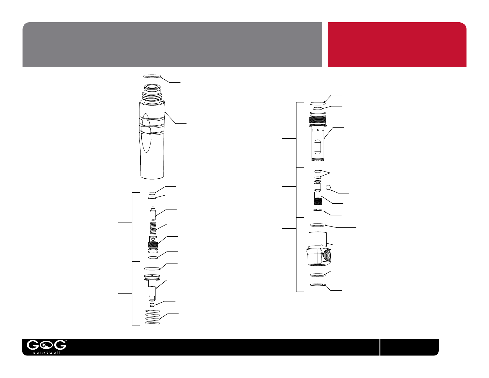
PARTS DIAGRAMS
RELIEF
VALVE
ASSEMBLY
REGULATOR
PISTON
SWIVEL
ASSEMBLY
VELOCITY
ADUSTER
SPRING
PLATFORM
OB9015 - REGULATOR
ASA O-RING
OM7006 - VRG. SEAL
VRG107 - VRG. PISTON
SPR033 - PRV. SPRING
VRG108 - VRG. RETAINING. SCREW
OB7010 - VRG. SEAL
XTC105 - ENVY REGULATOR
BODY
OM7014 - PISTON O-RING
VRG105 - REGULATOR PISTON
VRG106 - REGULATOR SEAL
SPR032 - REGULATOR SPRING
OM7014 - SPRING PLATFORM
O-RING
OU7010 - REAR SEAL
VRG102 - SPRING PLATFORM
OU9006 - VELOCITY ADJUSTER
O-RINGS
FLT002 - INLET FILTER
VRG104 - VELOCITY ADJUSTER
CLP005 - ADJUSTER C-CLIP
OM7014 - SWIVEL O-RING
VRG103 - VERTICAL REGULATOR
SWIVEL
OM7014 - SWIVEL O-RING
CLP006 - SWIVEL C-CLIP
VRG109 - VRG. WASHER
SWIVEL
ASSEMBLY
VELOCITY
ADUSTER
SPRING
PLATFORM
OM7014 - SPRING PLATFORM
O-RING
OU7010 - REAR SEAL
VRG102 - SPRING PLATFORM
OU9006 - VELOCITY ADJUSTER
O-RINGS
FLT002 - INLET FILTER
VRG104 - VELOCITY ADJUSTER
CLP005 - ADJUSTER C-CLIP
OM7014 - SWIVEL O-RING
VRG103 - VERTICAL REGULATOR
SWIVEL
OM7014 - SWIVEL O-RING
CLP006 - SWIVEL C-CLIP
GOGpaintball.com
25
Page 29
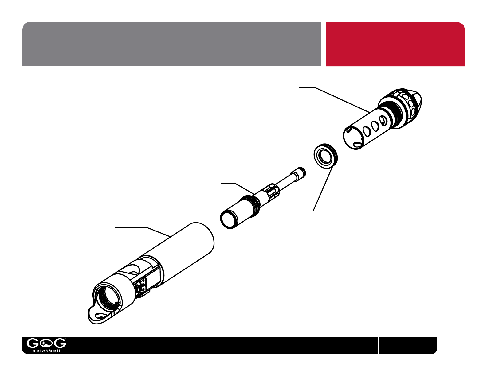
PARTS DIAGRAMS
BOLT ASSEMBLY
BOLT SLEEVE
ASSEMBLY
BOLT STOP
ASSEMBLY
BREECH ASSEMBLY
GOGpaintball.com
26
Page 30
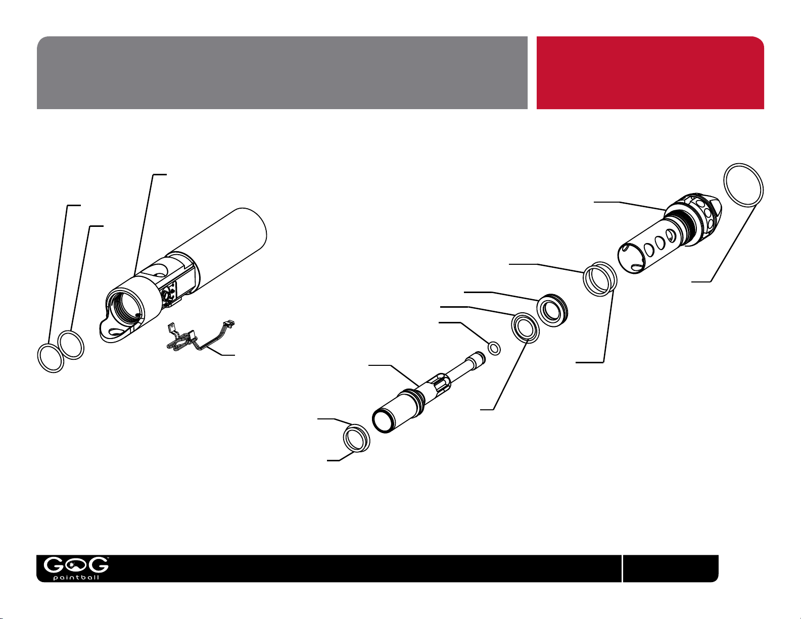
PARTS DIAGRAMS
XTC-103 EXTCY BREECH
OB9017
OH7017
XTC119 VISION
EYES
OH7M10
OU9015
XTC109
EXTCY BOLT
XTC110 BOLT STOP
OB7018
OU7010
OU7014
XTCY104
EXTCY BOLT SLEEVE
OB7018
OB7022
BOLT SLEEVE
FRICTION O-RING
OB7018
GOGpaintball.com
27
Page 31
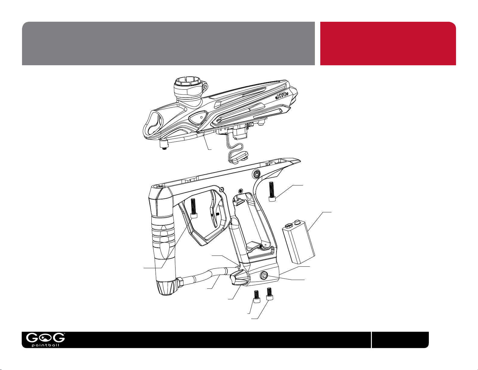
PARTS DIAGRAMS
XTC127
SSC011
SSC011
SSC014
SSC014
9v Alkaline
XTC136
FIT001
XTC137 ON/OFF KNOB
OU9006 ON/OFF O-Ring
(ON XTC137, NOT SHOWN)
HBR510
REMOVE ON/OFF KNOB FOR
ACCESS TO SCREWS
FIT002 ELBOW
(NOT SHOWN)
GOGpaintball.com
28
Page 32
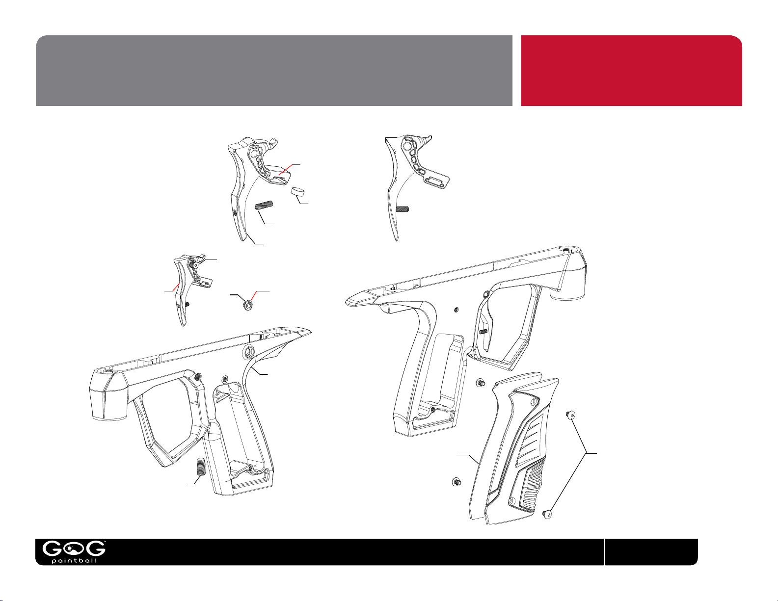
PARTS DIAGRAMS
SSS001 - POST TRAVEL ADJUSTMENT SCREW
XTC107 - ENVY TRIGGER
XTC124 - ENVY TRIGGER PIN
OB7M05 - TRIGGER PIN O-RING (SHOWN ON PIN)
O-RING PROVIDES FRICTION TO KEEP PIN SCREWED
INTO GRIP FRAME - DO NOT USE THREAD
LOCKER.
INSTALL TRIGGER ASSEMBLY
DOWN IN FROM THE
TOP.
XTC108 -EXTCY
POWER BUTTON
WHEN INSTALLING ON/OFF BUTTON
BE SURE THAT THE LINE IN THE POWER SYMBOL
IS POINTING UP.
MAGNET IS PRESS-FIT FLUSH WITH LEFT SIDE OF TRIGGER
MAG003 - TRIGGER MAGNET
(.250 x .100
RARE EARTH MAGNET)
COMPLETE EXTCY TRIGGER
ASSEMBLY
SOS010 - PRE-TRAVEL LIMIT SCREW
XTC106 - EXTCY GRIP FRAME
XTC116 - EXTCY RUBBER GRIP
SSB009 - 6-32 GRIP SCREW (4x)
GOGpaintball.com
23
Page 33
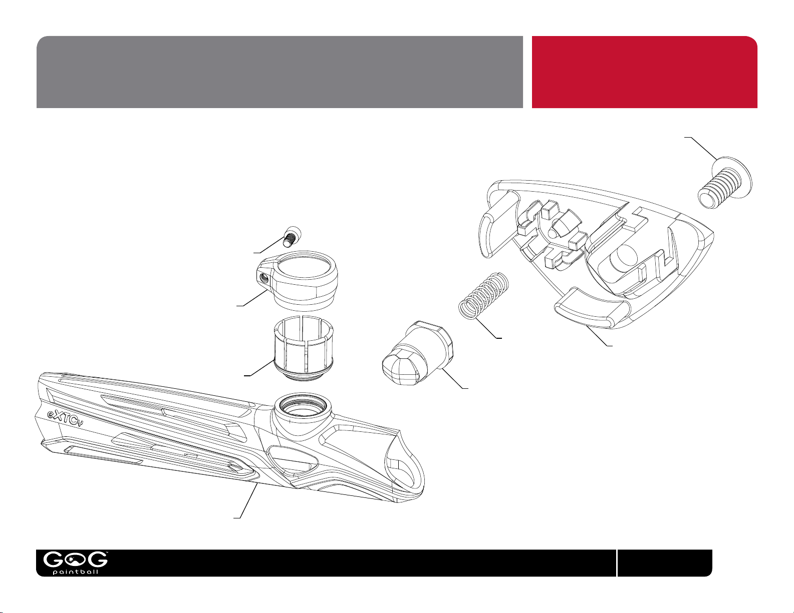
PARTS DIAGRAMS
XTC101 - EXTCY BODY COVER
XTC114 - EXTCY FEED TUBE
XTC115 - EXTCY FEED TUBE CLAMP
SSC009 FEED CLAMP SCREW
SSB010 VISION COVER SCREW
SPR036 - EXTCY BALL DETENT SPRING
XTC111 - EXTCY BALL DETENT
XTC112 - EXTCY VISION COVER (LEFT)
XTC113 - EXTCY VISION COVER (RIGHT)
GOGpaintball.com
24
Page 34
eXTCyTM Manual V1.10 © Copyright 2011, GOG Paintball, SA, all rights reserved.
eXTCy, GR33SE, GOG, GOG Paintball and the GOG Paintball logos are trademarks or registered trademarks of GOG Paintball, SA.
GOGpaintball.com
GOGpaintball.com
 Loading...