

GoFree Track-CelFi, Track-WiFi Installation Manuals
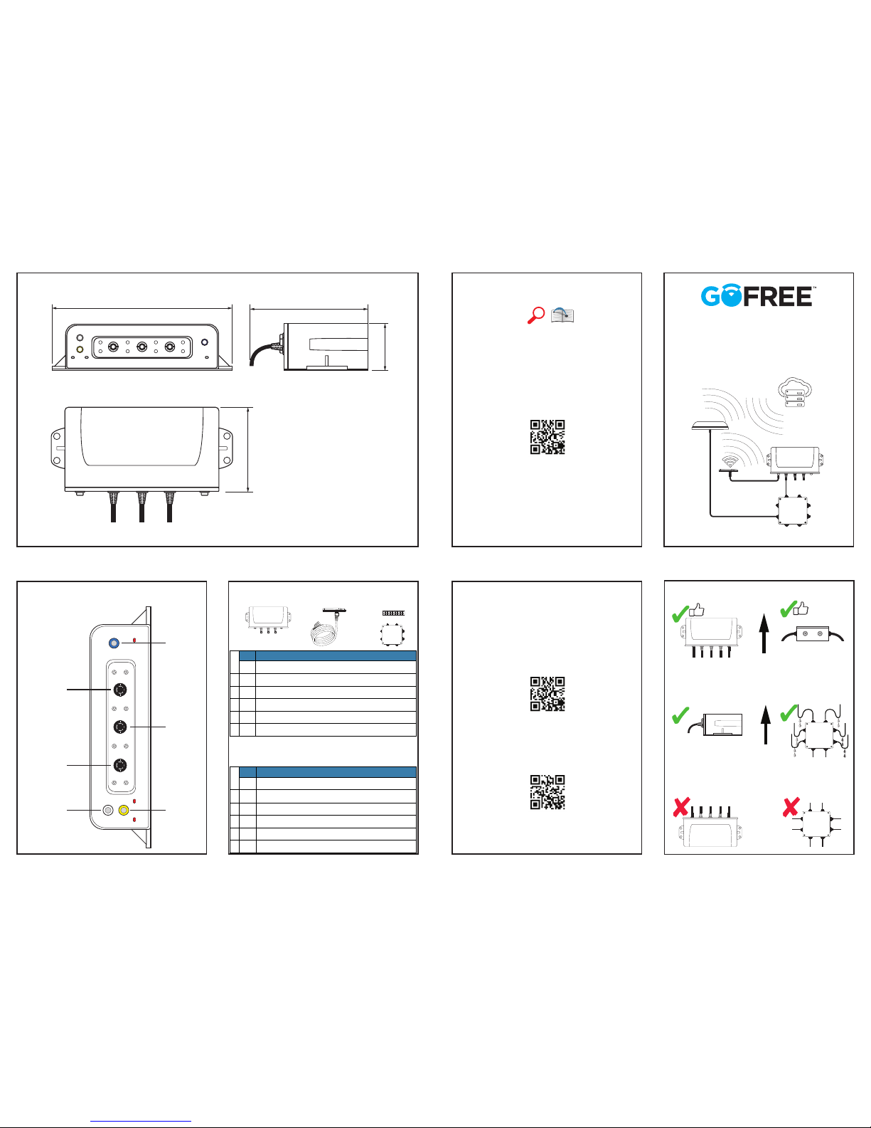
Getting started
Fully congure the device by accessing the
Track setting site via:
www.gofreemarine.com/vessel
Sensors installation guide
Available online via:
For all other information visit:
www.gofreemarine.com
Dimensions
Parts included
Connectors
Track-CelFi
Track-WiFi
Installation Guide
For technical specications and declarations, refer
to the product
website on:
*988-10977-001*
1
3
4
2
www.gofreemarine.com
COM
1
GPS
COM
2
COM 1 COM 2 GPS
176.0 mm (6.92”)
130.0 mm (5.11”)
47.0 mm (1.85”)
93.0 mm (3.66”)
Gnd
Pwr
1
2
3
4
5
Gnd IgnOut1 Out0
SAT-TTL-RS232 PCB
(Secured to case lid)
Aux2TxAux2RxAux2
Pwr
ADC1
Bilge Hatch TempOut2
Shore
Pwr
Mounting
UP
UP
Gnd
Pwr
1
2
3
4
5
Gnd Ign Out1Out0
SAT-TTL-RS232 PCB
(Secured to case lid)
Aux2TxAux2RxAux2
Pwr
ADC1
Bilge Hatch TempOut2
Shore
Pwr
Gnd
Pwr
1
2
3
4
5
Gnd Ign Out1Out0
SAT-TTL-RS232 PCB
(Secured to case lid)
Aux2TxAux2RxAux2
Pwr
ADC1
Bilge Hatch TempOut2
Shore
Pwr
COM
1
GPS
COM
2
COM 1 COM 2 GPS
CELLULAR
WLAN
PRIMARY I/O
1 x NMEA 2000
2 x J1939
SECONDARY I/O GPS
Qty Description
GoFree Track-CellFi Pack
1 1 Track-CellFi Unit
2 1 Track CELL/GPS/WLAN Antenna & 3m cable
3 2 9 pin terminal strip
4 1 Track junction box
1 Track, Misc. hardware kit, including screws, fuse and fuse holder
Qty Description
GoFree Track-WiFi Pack
1 1 Track-WiFi Unit
2 1 Track GPS/WLAN Antenna & 3m cable
3 2 9 pin terminal strip
4 1 Track junction box
1 Track, Misc. hardware kit, including screws, fuse and fuse holder
¼ Note: Use screws #6 x 5/8 PAN POZ AB to mount the junction
box.
¼ Note: Use screws #10 x 3/4 AB PAN POZ to mount the Track-
CellFi unit.
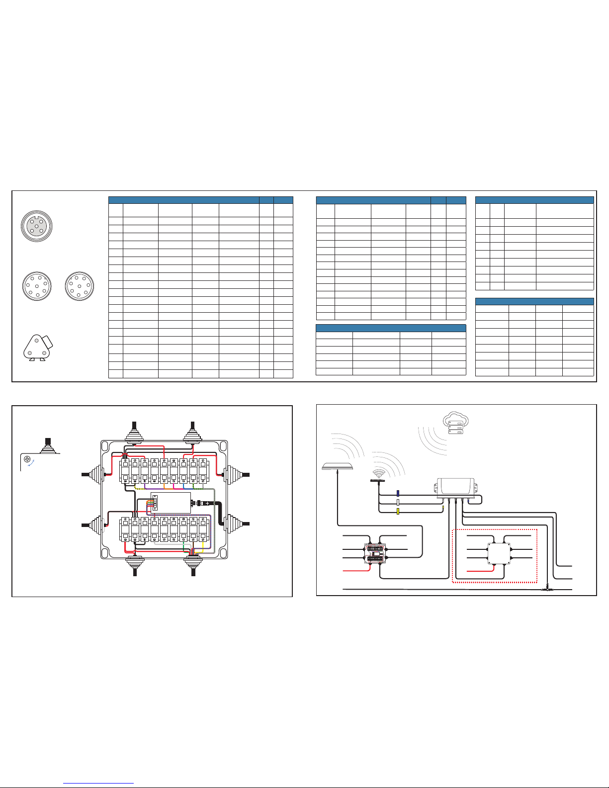
Connector wiring
Junction box
Recommended wiring
Wiring example
Satellite antenna
8 Pin Female Color In / Out Name
1 - -
2 Black Ground
3 - In RS232 RX
4 - Out RS232 TX
5 Red In 12 V DC
6 - - -
7 - - -
8 - - -
Satellite antenna - Junction box connector
Connector No. Color In /Out Name
1 Brown / Red In 12 V DC
2 Brown / Blue Out Aux1_TX
3 Brown / Green In Aux1_RX
4 Brown / Orange In Ext Sat
5 Black - Ground
Primary I/O
Wire Color Signal Desc’
Direction
(LMU)
Navico
V
LIMIT
A
1 Red VIN PWR Boat Power
12-32 V
2 Black GND PWR Boat Ground
12-32 V
3 White INPUT0 I Ignition
12-32 V
4 Pink ADC1 I -
12-32 V
5 Brown / Red VIN_VILT PWR EXT. SATELLITE
12-32 V
6 Brown / Orange AUX1_VCC PWR EXT. SATELLITE
3.3 V
7 Brown / Green AUX1_RX O EXT. SATELLITE
3.3 V
8 Brown / Blue AUX1_TX I EXT. SATELLITE
3.3 V
9 Yellow / Orange AUX2_VCC PWR -
3.3 V
10 Yellow / Green AUX2_RX O -
3.3 V
11 Yellow / Blue AUX2_TX I -
3.3 V
12 Blue INPUT 1 I ENTRY / HATCH
12-32 V
13 Orange INPUT 2 I WATER LEVEL
12-32 V
14 Violet INPUT 3 I SHORE POWER
12-32 V
15 Grey INPUT 4 I SPARE
12-32 V
16 Green / Black 1BB_T_DATA Signal TEMP SENSOR
4 V
17 Yellow / Black 1BB_GND GND TEMP SENSOR
4 V
18 Green OUTPUT 0 O - 250 mA
19 Brown OUTPUT 1 O - 250 mA
20 Yellow OUTPUT 2 O - 250 mA
Secondary I/O
Wire Color Signal Desc’
Direction
(LMU)
V
LIMIT
A
1 Black GND PWR
12-32 V
2 Yellow / Red VIN_FILT PWR
12-32 V
3 Green / White INPUT 5 I
12-32 V
4 Blue / White INPUT 6 I
12-32 V
5 Black / White INPUT 7 I
12-32 V
6 Orange / Black 1BB_R_DATA I/O
4 V
7 Blue / Orange OUTPUT 3 O
-
250 mA
8 Whote / Yellow OUTPUT 4 O
-
250 mA
9 Red / Green LED OUTPUT 1 O
4 V
10 Orange / Green LED OUTPUT 2 O
4 V
11 Black / Red ADC2 INPUT I
12-32 V
12 White / Red ADC3 INPUT I
12-32 V
13 Orange / Red ADC4 INPUT I
12-32 V
14 Blue / Red ADC5 INPUT I
12-32 V
NMEA 2000 / CAN - J Connector
Wire Pin Color Signal Desc
1 4 Yellow NMEA 2000 High
2 5 Green NMEA 2000 Low
3 3 Black / Yellow NMEA 2000 Ground
4 A Grey Port J1939 CAN 1 Low
5 B Blue Port J1939 CAN 1 High
6 C Black / Grey Port J1939 CAN 1 Ground
7 A Red Stbd J1939 CAN 2 Low
8 B Brown Stbd J1939 CAN 2 High
9 C Black / Red Stbd J1939 CAN 2 Ground
Gnd
Pwr
1
2
3
4
5
Gnd IgnOut1 Out0
SAT-TTL-RS232 PCB
(Secured to case lid)
Aux2TxAux2RxAux2
Pwr
ADC1
Bilge HatchTemp Out2
Shore
Pwr
Gnd Gnd
Pwr
1
2
3
4
5
Gnd
Gnd
Ign Out 0 Out 1Out 2
Satellite antenna
connector
(Secured to case lid)
Bilge HatchADC1 SpareTemp
Shore
Pwr
NMEA 2000 Network
12 V 12 V
In / Output
In / Output
In / Output
In / Output
In / Output
Primary I/O
Satellite
In / Output
In / Output
In / Output
In / Output
In / Output
In / Output
Iridium
Antenna
Cellular Com 1 *
* Cellular conectivity only available with a
Track CELL/GPS/WLAN Antenna & Track-CellFi Unit
WLAN Com 2
GPS
Junction
Box
Junction
Box
Secondary I/O
Engine ‡
J1939 Conection
Engine ‡
J1939 Port
GoFree Cloud
Track Unit*
Track
Antenna*
‡ Not compatible
with all SAE J1939
compatible engines,
see GoFree
technical support
for more details
Gnd Gnd
Pwr
Ignition
Sensor
Ships
Power
Bilge
Sensor
Entry
Sensor
Primary I/O
to Track
Satellite antenna
Cable (3 m)
Extention for additional
10 m available
Temperature
Sensor
Shore Power
Sensor
1
2
3
4
5
Gnd
Gnd
Ign Out 0 Out 1 Out 2
Satellite antenna
connector
(Secured to case lid)
Bilge HatchADC1 SpareTemp
Shore
Pwr
1
2
3 4
5
2
1
4 3
5
NMEA 2000
Male connector
1
1
7
7
6
6
5
5
2
2
3
3
4
4
8
8
1
7
6
5
2
3
4
8
Satellite
Male connector
Satellite
Female connector
A
B
C
J1939 DT04-3P
Deutsch Connector
Locked
Unlocked
1/4 Turn
 Loading...