

Page 1
G4-0049A
HDMI 2.0 2x4 Splitter 4K
with Downscaling
User's Guide
P/N: HDSplit24
Page 2

Thank you for purchasing from gofanco. Our
products aim to meet all your connectivity needs
wherever you go. For optimum performance
and safety, please read the instructions carefully
and keep this User’s Guide for future reference.
If you need more information about our
products, please visit www.gofanco.com. For
technical support, please email us at
[email protected]. For drivers/manuals
download, please go to www.gofanco.com/
download.
2
Page 3

Important Safety Notices
Please read safety instructions carefully before
installation and operation.
• Do not expose this unit to rain, heavy
moisture, or liquid
• Do not repair the device or open the housing
without professional guidance to avoid
electric shocks. Doing so may void your
warranty
• Keep the product in a well-ventilated
location to avoid damage from overheating
• Shut off power and make sure environment
is safe before installation
• Do not plug the HDMI cables in/out when
the device is in use to avoid cable damage
• Use the included DC5V power adapters
only. Make sure the specification matches
if using 3rd-party DC power adapters
• Do not use liquid or aerosol cleaners to
clean this unit, unplug the power before
cleaning
• Unplug the power cord when left unused
for a long period of time
3
Page 4

Introduction
The HDMI 2.0 2x4 Splitter 4K with Downscaling
allows you to distribute content from any of the
2 HDMI source devices to any of the 4 HDMI
display devices, it supports resolutions up to
4Kx2K@60Hz YUV 4:4:4 8bit.
Features
• Splits HDMI signals from any 2 source
devices to any 4 display devices
• Compliant with HDMI 2.0 and HDCP 2.2
• Video resolutions up to 4K@60Hz YUV4:4:4
• Supports downscaling for mixed 4K and
1080p display setups
Package Contents
• 1x HDMI 2.0 2x4 Splitter 4K with
downscaling
• 2x Mounting ears with 4 screws
• 4x Plastic pads
• 1x Power adapter
• 1x User's guide
4
Page 5

Installation Requirements
1. HDMI source device (computer, DVD
player, XBOX, PS3, etc)
2. HDMI display device (SDTV/Monitor,
HDTV/Monitor, projector, etc.)
3. UTP/STP CAT5e/6 cable following
IEEE-568B wiring standard
5
Page 6
Product Layout
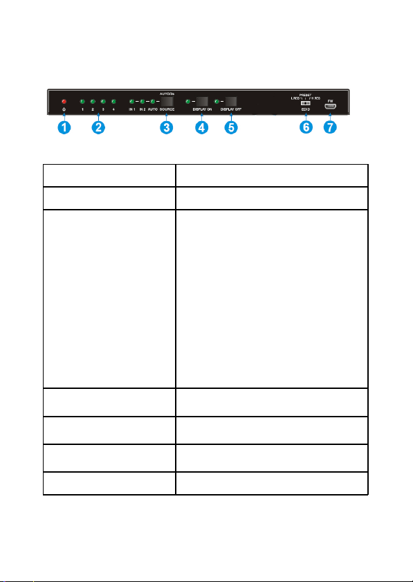
Front Panel
1. Power LED Lights up when power is detected
2. Output LEDs Lights up when HDMI ouput is active
A) Press to switch to the next sou rce de vice, the
corresponding LED will light up
B) Automatic Switching Mod e*: Press and hold
down for at least 3 seconds, the splitter will
automaticall y sel ect the first available active
source device starting with HDMI Input 1.
*Note: a) When a source device is connecte d or
3. Source Button and LEDs
4. Display On Button and LEDs
5. Display Off Button and LEDs
6. EDID
7. Firmware (FW) Micro USB port for firmware upgrade
turned on, the splitter will switch to it
automatically; b) When an active source device
is removed or turned off, the splitter will switch
to the next active so urce device automatically;
c) When the splitter is power cycled, it will
resume from the last device setup
C) To exit automatic switching mode, press and
hold down the bu tton for at least 3 seconds
again
Press to turn on the disp lays. LED bl inks when
the button is pres sed
Press to turn off the displays. LED blinks when
the button is pres sed
3-Pin DIP switch for E DID ma nageme nt. Refe r
to EDID Management for details
6
Page 7
Back Panel
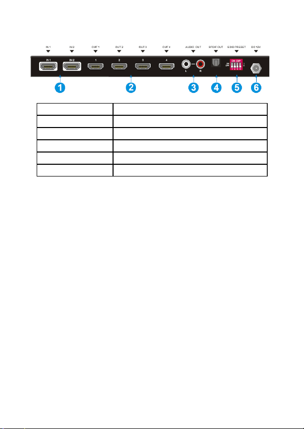
1. HDMI Inpu ts Connect HDMI sourc e device s here
2. HDMI Outputs Connect HDMI display devices here
3. RCA Audio Output Analog Stereo audio output
4. SPDIF Output Toslink connector for optical digital audio output
5. EDID DIP Switch 4-Pin DIP switch for setting EDID
6. Po wer Ada pter Jac k Connect the included power ad apte r here
Hardware Installation
1. Power off all devices including your HDMI
source and HDMI display(s).
2. Connect your HDMI source devices to the
Splitter's HDMI Input connectors with an
HDMI cable (HDMI cable not included).
3. Connect your HDMI displays to the HDMI
ouput connectors with an HDMI cable
(HDMI cable not included).
4. Plug the included power adapter into the
power adapter jack, then plug the power
adapter into a reliable power source.
9. Power on all connected devices.
10. The Splitter is ready for use.
7
Page 8
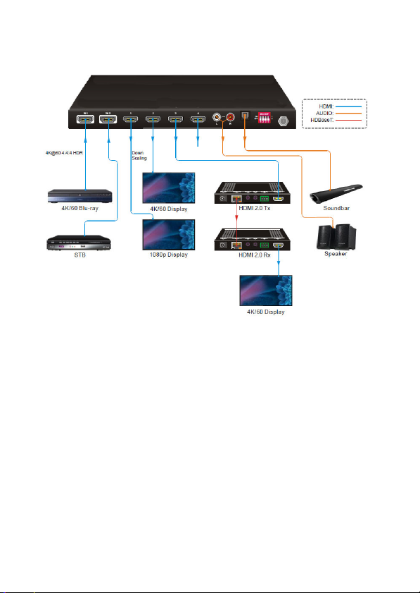
Connection Diagram
8
Page 9
EDID Management
The Extended Display Identification Data (EDID)
is used by the source device to match its video
resolution with the connected display(s). By
default, the source device obtains its EDID from
the first connected display. However, since
displays with different capabilities are often
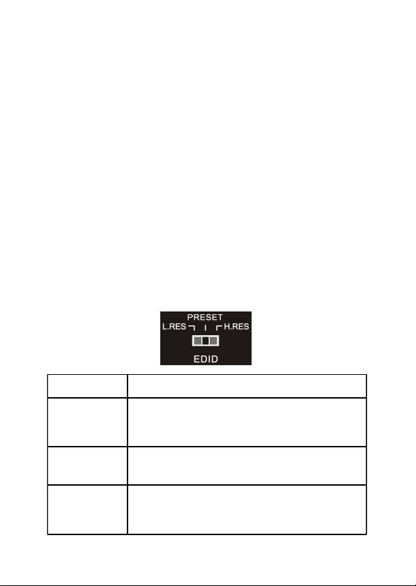
connected to the splitter, the 3-pin DIP switch on
the front panel and the 4-pin DIP switch on the
rear panel can be used in combination to set the
EDID to a fixed value for ensuring video
compatibility for mixed display setup.
Preset EDID
Switch Status Description
The splitter reads EDID from all connected displays, and
L. RES
PRESET
H.RES
then the so urce device will au tomatically us e the EDID
with the lowest resolution. This EDID setting offers the
best video compatibility in mixed display setups
This mode acti vates the 4-Pin DIP switch on the rear
panel , it can be u sed for selecting p redefine d EDID and
customizing and EDID as needed
The splitter reads EDID from all connected displays, and
then the so urce device will au tomatically us e the EDID
with the hi ghes t resolution. This EDID se tting offers the
best video compatibility in identical display setups
9
Page 10
Predefined EDID
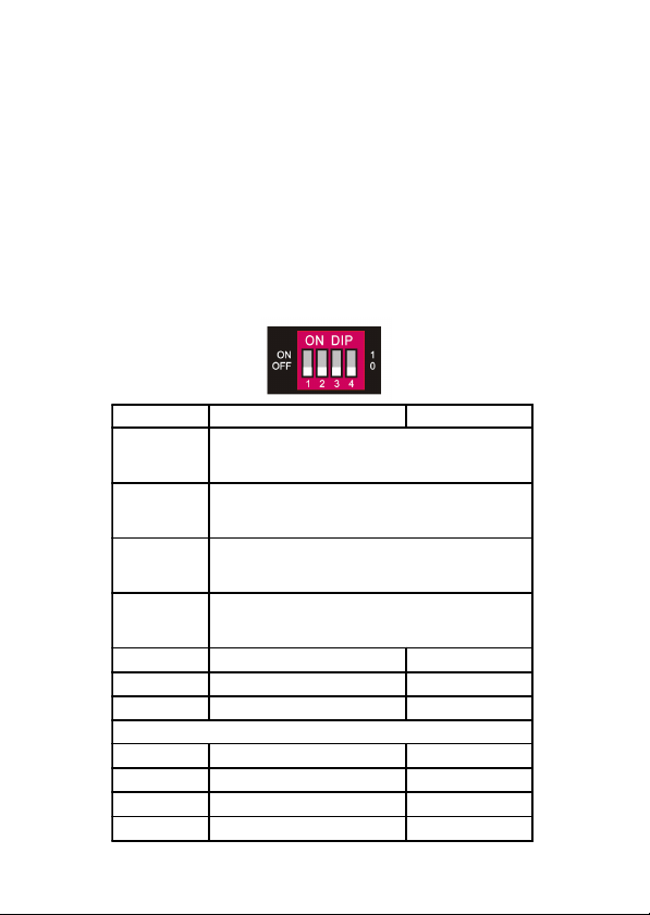
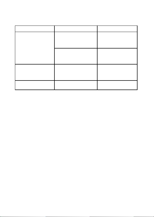
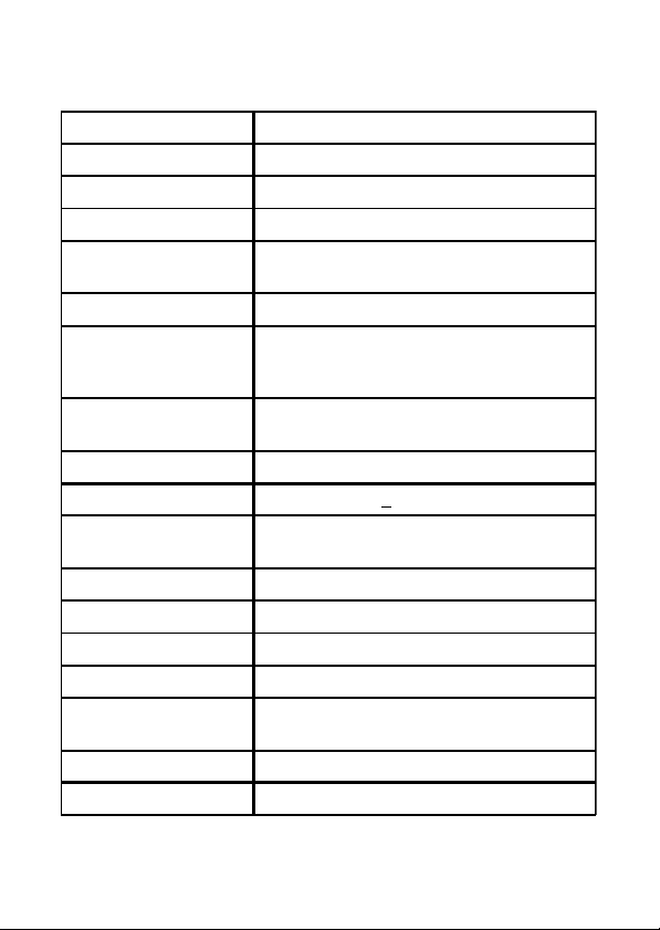
When the 3-Pin DIP switch on the front panel is in
PRESET mode, the 4-Pin DIP switch on the rear
panel can be used to set the EDID to a built-in fixed
value. Use the following table to determine the
settings for the 4-Pin DIP switch for specific video
resolution and audio capabilities.
The lower switch position represents "0", and the
upper switch position represents "1".
Switch Status Video Resolutions Audio F ormat
0000
0001
0010
0011
0100 720p LPCM
0101 1080p LPCM
0110 1080p DTS/Dolby
0111 3840x2160p@30Hz LPCM 2ch
1000 3840x2160p@ 30Hz DTS/Dolby 5.1ch
1001 3840x2160p@60Hz LPCM 2ch
1010 3840x2160p@ 60Hz DTS/Dolby 5.1ch
10
The source device will automatically obtain the EDID
of the display connected to HDMI Out 1 and use it for
all the connected displays
The source device will automatically obtain the EDID
of the display connected to HDMI Out 2 and use it for
all the connected displays
The source device will automatically obtain the EDID
of the display connected to HDMI Out 3 and use it for
all the connected displays
The source device will automatically obtain the EDID
of the display connected to HDMI Out 4 and use it for
all the connected displays
The settings below support mixed 4K and 1080p displays
Page 11

Firmware Upgrade
Firmware files can be downloaded from gofanco's
website, when they become available. Go to
www.gofanco.com/download, and use the part
number to search for your device.
Follow the steps below to upgrade the firmware
through the Micro USB port.
1. Connect the splitter to the PC using a USB
cable.
2. Power on the splitter, the PC will
automatically detect a U-disk named
Bootdisk.
3. Double click to open the U-disk, a file named
Ready.txt will be displayed.
4. Copy the latest upgrade file (.bin),
downloaded earlier, to the Bootdisk.
5. Reopen the U-disk, if you see the file
Success.txt the firmware update is
successful.
6. Remove the USB cable after successful
firmware upgrade and power on the splitter.
11
Page 12
Troubleshooting
Problem Potential Cause Solution
The HDMI cables may not be
connected properly or may be
Color loss or no video
signal on HDMI display
No si gnal ou tput to the
displays
The scree n is sho wing
pixilated or broken images
damaged
The display is not compatible
with the current output
resolu tion
The HDMI cable may not be
connected properly or may be
damaged
Poor quality or damaged
HDMI cable
Check whether the HDMI
cables are connected
properly and in good
working condition
Make su re the resol ution of
the display(s) is compatible
with the current output
resol ution
Check the HDMI cable
connectio n for good
working condition. Replace
the HDMI cable if needed
Change to higher quality
HDMI cabl e
12
Page 13
Specifications
HDMI v2.0
HDCP v2.2
Input Connector 2 HDMI
Output Connector 4 HDMI
Resolution (Input &
Output)
Bandwidth 18Gbps
HDMI Audio
Stereo Analog L/R
Audio
Toslink Digital Audio PCM, Dolby Digital, DTS, DTS-HD
Frequency Response 20Hz ~ 20KHz, +
THD + N
SNR >80dB, 20Hz ~ 20KHz bandwidth
Power Consumption 12W (Max)
Dimensions (WxHxD) 9.13" x 0.79" x 3.93"
Weight 1.45lbs
Operating
Temperature
Storage Temperature -13 F to 158 F
Relative Humidity 10% to 90%
Up to 4Kx2K@60Hz YUV 4:4:4 8Bit
LPCM 7.1, Dolby Atmos, Dolby TrueHD,
Dolb y Digital Plus, DTS:X, and DTS-HD
Master Audio, pass-through
PCM
3dB
<0.05% (-80dB), 20Hz ~ 20KHz bandwidth,
1KHz sine at 0dBFS level (or max level)
14 F to 131 F
13
Page 14

Blank Page
14
Page 15

Disclaimer
The product name and brand name may be
registered trademarks of related manufacturers.
TM and ® may be omitted on the user’s guide.
The pictures on the user’s guide are just for
reference, and there may be some slight
differences with the actual products.
We reserve the right to make changes without
prior notice to a product or system described
herein to improve reliability, function, or design.
15
Page 16

Thank you for choosing gofanco
www.gofanco.com
 Loading...