

Page 1
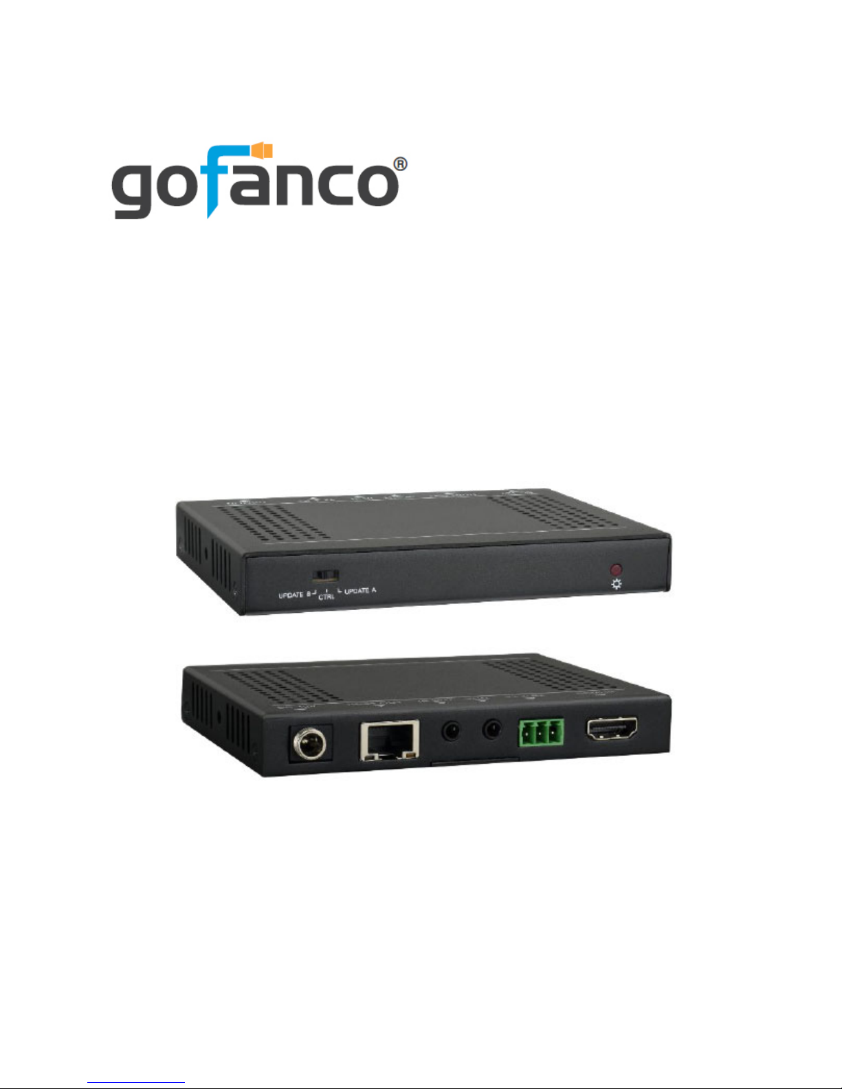
HDbaseT HDMI 2.0 Extender
with HDR
User's Guide
G4-0045A
P/N: HDbaseT-HDR
Page 2

2
Thank you for purchasing from gofanco. Our
products aim to meet all your connectivity needs
wherever you go. For optimum performance
and safety, please read the instructions carefully
and keep this User’s Guide for future reference.
If you need more information about our
products, please visit www.gofanco.com. For
technical support, please email us at
[email protected]. For drivers/manuals
download, please go to www.gofanco.com/
download.
Important Safety Notices
Please read safety instructions carefully before
installation and operation.
• Please pay close attention to all warnings
and hints for this device
• Do not expose this unit to rain, heavy
moisture, or liquid
• Do not repair the device or open the
enclosure without professional guidance
to avoid electric shocks. Doing so may void
your warranty
• Keep the product in a well-ventilated
location to avoid damage from over heating
Page 3

3
• Shut off power and make sure environment
is safe before installation
• Do not plug the HDMI cables and IR
Extension cables in/out when the device is
in use to avoid cable damage. Make sure
they are plugged into the correct ports
• Use the included DC12V power adapter
only. Make sure the specification matches
if using 3rd-party DC power adapter
Package Contents
• Transmitter (TX) & Receiver (RX)
• IR Blaster & IR Receiver Extension Cables
• Power Adapter (1x)
• 3-Pin Phoenix Connector and Plastic
Cushions (8x)
• RS-232 Cables (2x)
• Mounting Ears and Screws (4x)
• User's Guide
Page 4

4
Introduction
The HDbaseT HDMI 2.0 Extender with HDR
extends HDMI signals up to 70 meters (230ft)
with PoC using an economical CAT5e/6 cable.
Features
• Extends HDMI transmissions up to 70m
(230ft) @ 1080p and 40m (130ft) @ 4K
• Supports UHD 4K/60Hz/4:4:4. HDMI 2.0
& HDCP 2.2 compliant and backward
compatible with previous versions
• Supports HDR with 18Gbps bandwidth
• Supports CEC, Bi-directional IR, and
RS-232 pass-through
• Bi-directional PoC (Power over Cable)
support. Only 1 power adapter required to
power both the transmitter and receiver
• Features firmware update options for future
compatibility expansion
Page 5
5
Product Layout
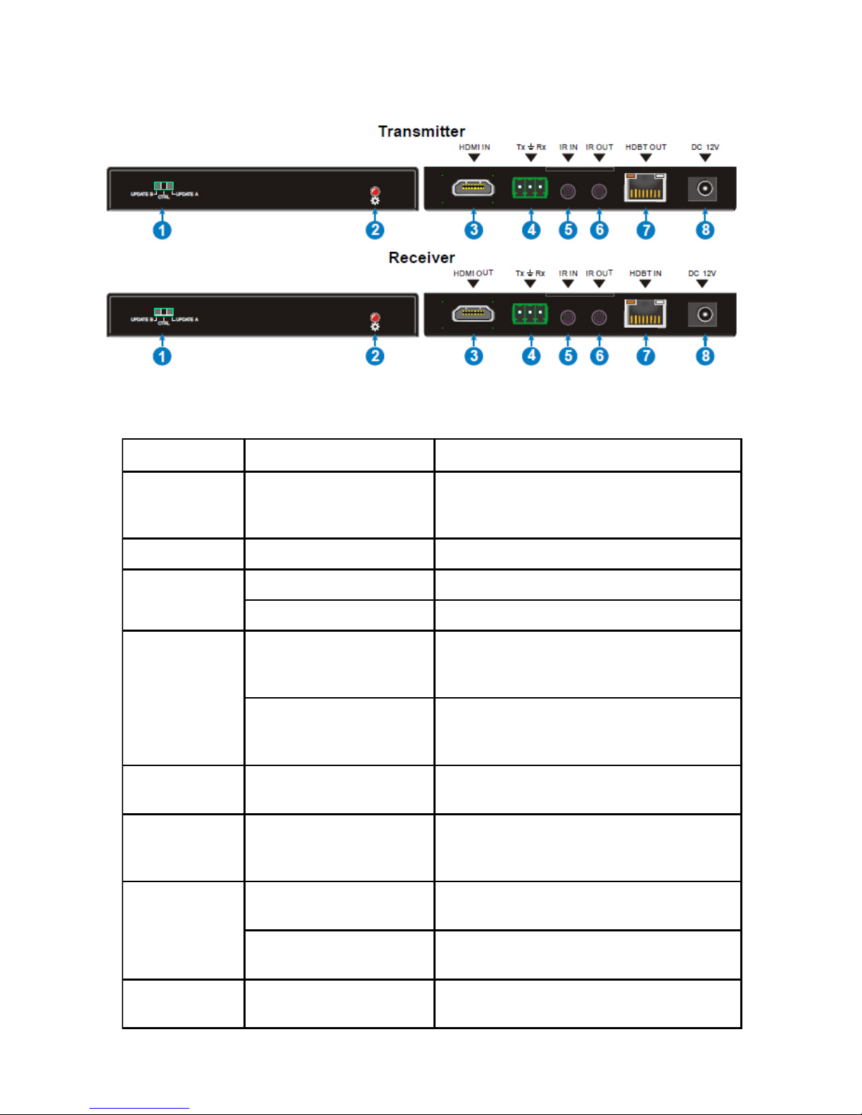
Figure 1: Transmitter and Receiver
No. Name Description
1 Mode Switcher
- CTRL: RS-232 pass-through
- UPDATE A: Firmware update mode
- UPDATE B: Update compression IC
2 Power LED Red when power adapter is connected
3
HDMI IN (Transmitter) Connects to your HDMI source
HDMI OUT (Receiver) Connects to your HDMI display
4
3-Pin Terminal Block
(Transmitter)
RS-232 pass-through. Connects to your
computer's RS-232 port using the included
RS-232 cable
3-Pin Terminal Block
(Receiver)
RS-232 pass-through. Connects to your
end device's RS-232 port using the
included RS-232 cable
5IR IN
Plug the IR Receiver Extension cable here,
receives signals from an IR remote control
6IR OUT
Pl ug the IR Blaster Extension cable here,
transmitts the signals from an IR remote
control
7
HDBT O UT (Transmitter)
Connects to the HDBT IN of the Receiver
using a CAT5e/6 cable
HDBT IN (Receiver)
Connects to the HDBT OUT of the
Transmitter using a CAT5e/6 cable
8 DC 12V Power Jack
Plug the included power adapter into
either power jack, to power both units
Page 6

6
IR Extenders
• IR Blaster cable: Plug into the Transmitter's
or Receiver's IR OUT to emit IR signals
• IR Receiver cable: Plug into the Receiver's
or Transmitter's IR IN to receive IR signals
Control your media player (such as DVD) at the
TV side using the media player's remote
controller
• Plug the IR Receiver cable to the Receiver's
IR IN port
• Plug the IR Blaster cable to the Transmitter's
IR OUT port
Control your TV at the media player side using
the TV's remote controller
• Plug the IR Receiver cable to the
Transmitter's IR IN port
• Plug the IR Blaster cable to the Receiver's
IR OUT port
Note: Incorrect placement of the IR cables may
result in cable failures. Please check carefully
before plugging in the IR cables. The IR Receiver
cable always plugs into an IR IN port & IR
Blaster cable always plugs into an IR OUT port.
Page 7

7
Installation Requirements
1. HDMI source device (computer, DVD
player, XBOX, PS3, etc).
2. HDMI display device (SDTV/Monitor,
HDTV/Monitor, projector, etc.).
3. UTP/STP CAT5e/6 cable following
IEEE-568B wiring standard.
Hardware Installation
1. Power off all devices including your HDMI
source and HDMI display.
Transmitter
2. Connect your HDMI source device to the
Transmitter's HDMI IN connector with a
HDMI cable (HDMI cable not included).
3. Optional: Connect your RS-232 source
device with the included cable.
Receiver
4. Connect your HDMI display to the
Receiver's HDMI OUT connector with a
HDMI cable (HDMI cable not included).
5. Optional: Connect your RS-232 end device
with the included cable.
Page 8

8
6. Plug your CAT5e/6 cable between the
Transmitter's HDBT Out and Receiver's
HDBT IN.
7. Optional: Connect the IR Extension cables
according to the instructions on page 6.
8. Plug the included power adapter into either
the Transmitter's or Receiver's power jack,
then plug the power adapter into a reliable
power source. Note: Only one power
adapter is needed to power both
Transmitter and Receiver.
9. Power on all connected devices.
10. The HDMI extender is ready for use.
Page 9
9
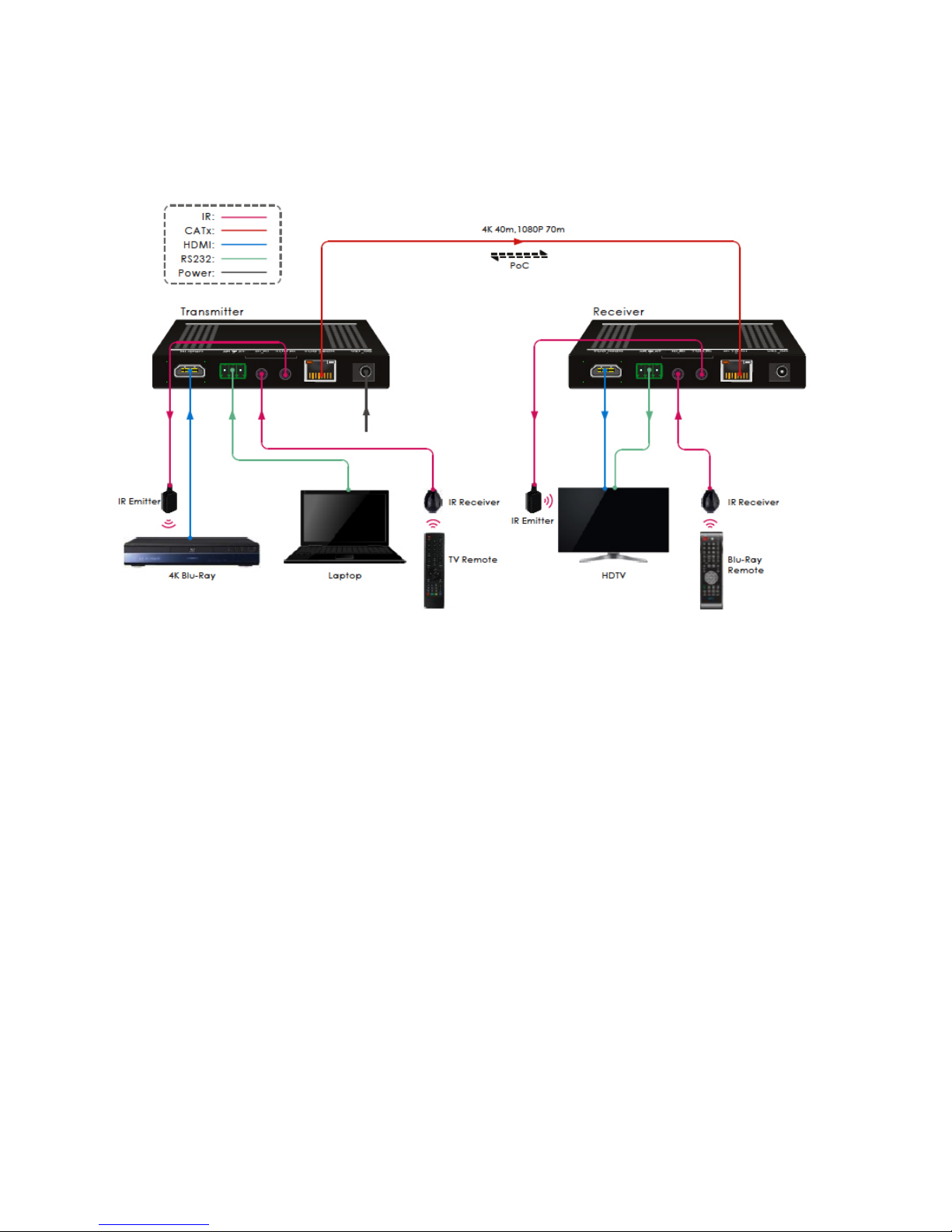
Application
Figure 2:
Page 10

10
FAQ & Solutions
Q: There is no video output or audio and
video display is not normal:
A: 1) Use a shorter network cable.
Q: The extender is not working properly:
A: 1) Please check the cable lengths below:
- HDMI cables: Up to 5m (Input and Output)
- Network cables (CAT5e/6):
- Up to 70m @ 1080p
- Up to 40m @ 4K
Page 11

11
Specifications
Item Description
Transmission Distance
1080p: up to 70m (230ft)
4Kx2K: up to 40m (130ft)
Resolution Up to 4Kx2K @ 60Hz, 4:4:4
Bandwidth 18Gbps
Standards HDMI 2.0 & HDCP 2.2
Power Consumption 14W (max)
Operating Temperature 0 to 40 C
Storage Temperature -10 to 50 C
Humidity 0% to 90%
Power Supply
Input: 100VAC - 240VAC, 50/60Hz
Output: 12VDC / 2A
Disclaimer
The product name and brand name may be
registered trademarks of related manufacturers.
TM and ® may be omitted on the user’s guide.
The pictures on the user’s guide are just for
reference, and there may be some slight
differences with the actual products.
We reserve the right to make changes without
prior notice to a product or system described
herein to improve reliability, function, or design.
Page 12

Thank you for choosing gofanco
www.gofanco.com
 Loading...