

Page 1

DIN EN ISO 9001
Documentation Rev. 08
SR-Module HG 76360 ZA
Operational Description, Block Diagrams and Users Manual
Revision - History Documentation
Rev. Author Date Reason fo Modification
01 TN 27.05.2009 Reissued
02 TN/TG/TK 21.07.2009 Adapted to firmware V0.17
03 TN/TG 26.10.2009 Adapted to firmware V0.22 (page.5 and page.8)
04 TN/TG 03.09.2010 V0.24-V0.28 updated and commissioning
05 TN/TG 09.12.2010 V0.29 updated
06 TN/TG 24.03.2011 P. 18, Table 8, Bit 3 and 4, Rx, Tx changed
07 TN 12.05.2011 Block diagram included
08 TN 01.06.2011 Labels for type approvals added, page 27
09 TN 11.07.2011 minor changes
Revision - History Software
Rev. Date Reason for Modification
V0.20 10.08.2009 Module doesn’t start before Host configuration
V0.21 11.09.2009 Debug version for log- analysis
V0.22 13.10.2009 Different bug fixes
Master of last connection is stored on slaves
Packets have to be received successfully on both channels if slave
looks for a master
The configuration memory will be regularly written with meaningful
values before each interrupt calling for configuration
V0.24 29.01.2010 Detection and signalisation of burst errors
V0.26 28.04.2010 Reading bus- test and debug information
V0.28 11.08.2010 Quicker activation of radio chips (Warning: unstable)
V0.29 16.08.2010 The “Lost-Sync” interrupt (BIT 5) is now redefined to a “Lost- Reg”
interrupt, as already defined before.
If text debugdata are provided, a SetDebugAvailable is set now,
otherwise 0 (see GRFExternInterface, i.e. after SerDebug).
So far only values from 1- 10 were correctly processed for the
Master ID. From now on the Master ID can be set up to a value
of 255 (as usual, only more options). The automatic search
function only scans the first 10 options. Thus a conflict in an
environment with a lot of operational systems can be avoided.
Created: TN, 21.02.2011 Page 1 of 32 S_01125-
A1_E_Documentation_R09.doc
Page 2

DIN EN ISO 9001
Table of Contents
SR-Module HG 76360 ZA......................................................................................................1
Revision - History Documentation.......................................................................................1
Revision - History Software.................................................................................................1
Table of Contents ...............................................................................................................2
Documentation.....................................................................................................................4
Short-range transmission module (SR module for Transmodule)........................................4
General points ....................................................................................................................4
Block diagrams...................................................................................................................5
Timing.................................................................................................................................6
Signal integrity....................................................................................................................6
Registering a new vehicle, solving slave to master allocation problems..............................7
Allocating time slot to a sledge number and slave ID ..........................................................7
Sledge malfunction.............................................................................................................8
Commissioning new machine / new facility.........................................................................8
Commissioning, service (controlled by host).......................................................................9
Standard operation.............................................................................................................9
Memory configuration / structure.........................................................................................9
Configuration....................................................................................................................10
Start- Configuration register from offset 0x0400 (RXDPRAM):..........................................11
Frequency Hopping...........................................................................................................11
Data Memory....................................................................................................................12
Telegram Memory Configuration (received from offset 0x400)..........................................12
Telegram memory configuration (transmitting from offset 0x0000)....................................12
Status Information.............................................................................................................13
Control- and Status register (CTRL register from offset 0x800).........................................14
CRC Checksum................................................................................................................15
Initialising Process............................................................................................................16
Communication Cycle.......................................................................................................17
Timing...............................................................................................................................17
Time Slots.........................................................................................................................17
LED Status Signalling.......................................................................................................18
Module is configured as slave.......................................................................................18
Module is configured as master.....................................................................................18
Interrupts ..........................................................................................................................19
Write access..................................................................................................................19
Error analysis....................................................................................................................20
Bus test.............................................................................................................................20
Debug Log.......................................................................................................................20
Firmware Update- Serial...................................................................................................21
Cable Allocation................................................................................................................22
Firmwareupdate................................................................................................................22
Commands for the firmware update..................................................................................22
hCStartUpgrade............................................................................................................22
hcStartUpgradeDistribution ...........................................................................................22
hcExecuteLocalUpgrade...............................................................................................22
Assembly diagram, position of solder bridges in relation to IRQ setting ............................23
Commissioning for wireless measurements......................................................................24
Starting data transmission.............................................................................................25
Sending a continuous carrier:........................................................................................26
Setting up a wireless link...............................................................................................26
Labelling...........................................................................................................................27
Labelling of host device:................................................................................................27
Created: TN, 21.02.2011 Page 2 of 32 S_01125-
A1_E_Documentation_R09.doc
Page 3

DIN EN ISO 9001
RF Exposure information:..............................................................................................27
Antenna:........................................................................................................................27
Specifications....................................................................................................................28
Glossary ...........................................................................................................................29
References:......................................................................................................................29
Structure of configuration data (Source code excerpt) ......................................................30
Structure of status information (Source code excerpt).......................................................31
FCC ID: NUDHG76360
This device complies with part 15 of the FCC Rules.
Operation is subject to the following two conditions:
(1) This device may not cause harmful interference, and
(2) this device must accept any interference received,
including interference that may cause undesired
operation.
Modifications not expressly approved by this company
could void the user's authority to operate the equipment.
The SR-radio module HG 76360 meets the requirements according to R&TTE Directive
1999/5/EC:
Safety/Health: EN 60950-1:2006
EN 50371:2002
EMC: EN 301 489-1 V1.8.1:2008-04
EN 301 489-3 V1.4.1:2002-08
Radio: EN 301 440-2 V1.2.1:2008-05
For more information according labelling see on page 27.
Created: TN, 21.02.2011 Page 3 of 32 S_01125-
A1_E_Documentation_R09.doc
Page 4

DIN EN ISO 9001
Documentation
Short-range transmission module (SR module for Transmodule)
General points
The SR module offers reliable, contact- free data transmission with real-time capability of
data transmission within a set time frame between a Transmodule master control / master
host, referred to in the following as a base station and up to 32 mobile, rail- mounted
carriage controls / slave hosts, referred to in the following as mobile station.
The SR modules communicate with the hosts using a PC / 104 structure. Data access is in
16-bit mode. External access is provided via the ISA bus and via a Dual- Ported RAM
(DPRAM). There is an interrupt for events that can be configured with solder bridges.
The structure of the SR modules for the base station and mobile station are identical.
A configuration parameter tells the module whether it is being used as master, slave or is
inactive. The SR modules have two separate wireless modules that operate in the ISM
frequency band between 2400 MHz and 2483.5 MHz. These can be operated in full, semiduplex or fully redundant mode with the Simplex procedure (alternating duplex). Currently
the system is operated in Simplex-redundant mode. Data is either sent or received at the
same time on both channels. High levels of availability are more important to the application
than speed. In redundant mode, the same data is transmitted simultaneously on different
frequencies, so that the likelihood of interrupting the entire transmission is almost zero. The
channel spacing is 40 MHz, so that narrow band interferences can be concealed.
The wireless transmission procedure is handled via an ARM7 derivate in conjunction with an
FPGA.
The high- frequency transmission is carried out on the stationary side via a radiating cable,
which the SR master module’s two wireless channels are connected to directly using a 3 dB
coupler / splitter. The SR mobile modules link their signal using a double coupler to the
Radiating cable. The couplers are working bi-directionally.
Depending on each time frame, the frequencies change (adaptive frequency hopping) to
allow other ISM band users interruption- free communication. Channels that are occupied or
experiencing interference are identified by CRC faults and passed over.
The mobile SR modules do not only give the slave- host their according telegram, but
telegrams for all vehicles. As a result, the slave- hosts are informed about the target status
of all other vehicles. After receiving the data and transmitting it into the DPRAM, an interrupt
is triggered that tells the vehicle’s computer that up-to-date data is available. The vehicle
computer must only read off the data within a certain data frame, so that the buffer for the
next transmission is free. Direct communication between the slave- hosts with one another is
not envisaged.
Each SR module has an RS- 232 interface, not used in normal mode, for directly debugging
and for text and diagnosis purposes, as well as software updates. There is a special terminal
program for this.
Created: TN, 21.02.2011 Page 4 of 32 S_01125-
A1_E_Documentation_R09.doc
Page 5
DIN EN ISO 9001
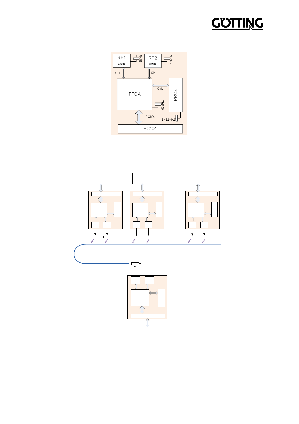
Block diagrams
Figure 1
Figure 1 shows the block diagram of one SR-module. One pcb includes two radio-modules,
a controlling FPGA and an arm processor. Figure 2 shows one complete system, including
the master-module, the radiating cable and up to 32 slave modules. The two antenna ports
of the master module are connected to a power combiner, connected to the radiating cable.
SLAVE 1
SLAVE 2
SLAVE 32
SPI
RF1
2.4Ghz
FPGA
PC104
PC104
RF2
2.4Ghz
PC104
PC104
RF2
2.4Ghz
RF2
SPI
Cntl.
SPI
2.4Ghz
MASTER
Cntl.
Processor
………...
SL2
Processor
RF1
SPI
SPI
2.4Ghz
RF1
2.4Ghz
FPGA
Cntl.
SPI
SL1
FPGA
SPI
RF1
2.4Ghz
FPGA
PC104
PC104
RF2
2.4Ghz
Processor
Cntl.
SPI
SL32
50R
Processor
PC104
PC104
HOST
Figure 2
Created: TN, 21.02.2011 Page 5 of 32 S_01125-
A1_E_Documentation_R09.doc
Page 6
DIN EN ISO 9001
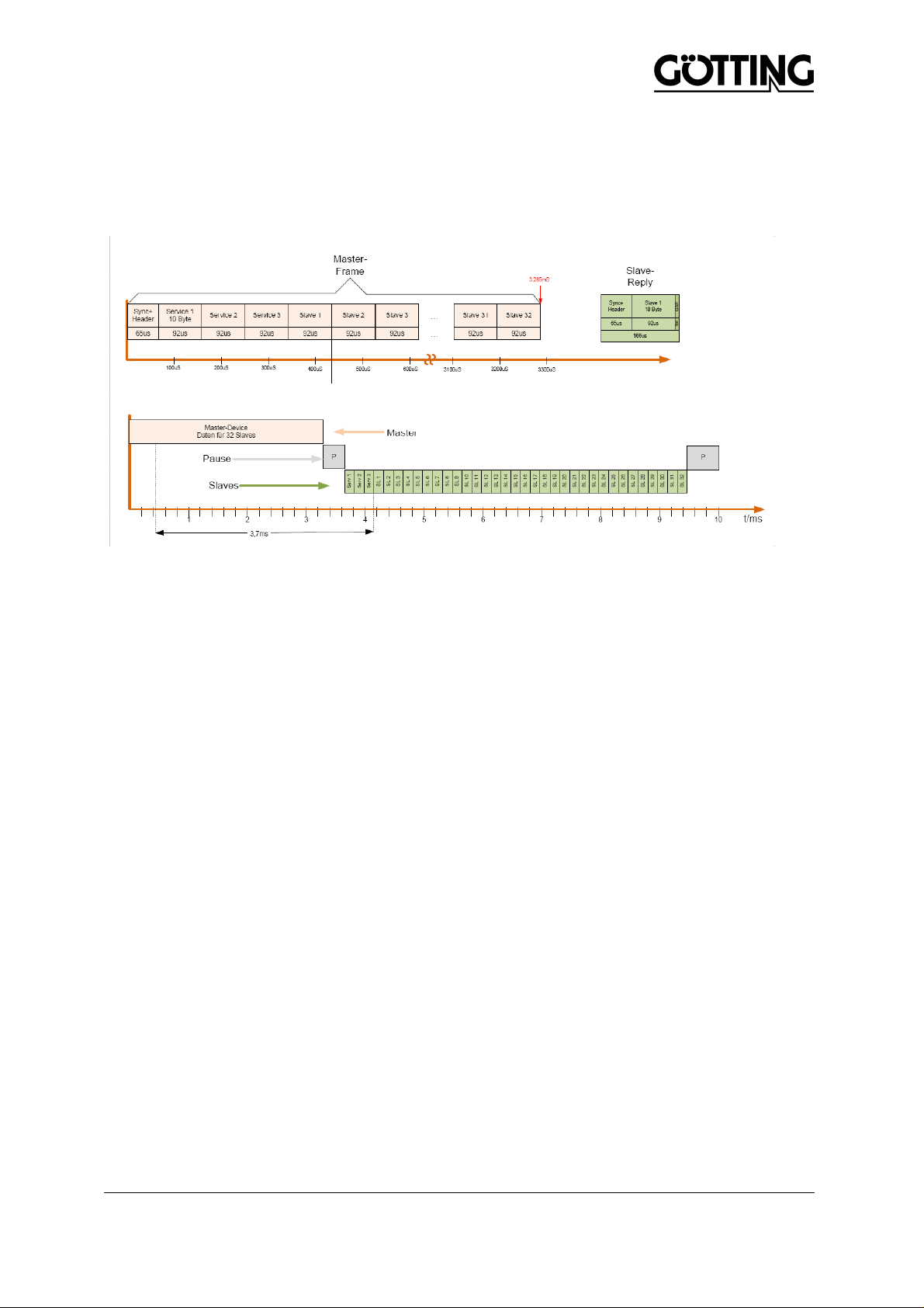
Timing
Because transmission takes some time, the master SR module controls the overall timing. It
should be assumed that the master- host is in the position to send on or pick up data at
adequate speed. There are differences in the timing (Figure 3) between the master and the
slave- module.
Figure 3
Signal integrity
Errors in the data are identified by using addresses and creating a CRC check sum.
Incorrect data is rejected, there is no FEC (forward error correction). The transmission is not
repeated, as this would take just as long as transmitting new, up-to-date data. When
transmission is carried out on two different frequencies at the same time, there may be
interference in one of the two data sets, but the correct data set is displayed. If errors
accumulate on one channel, a new channel can be selected. In each master frame, the next
bottom channel to be used is coded. The top channel is 40 MHz above the bottom one. The
information is available to both channels so that switching works reliably, even if there is
interference on another channel. A new subscriber scans all 40 available channels for 10 ms
each and is then up to date very quickly. As the cycle is 10 milliseconds, this procedure
takes a maximum of 400 ms.
The block error rate determines the signal integrity.
Created: TN, 21.02.2011 Page 6 of 32 S_01125-
A1_E_Documentation_R09.doc
Page 7

DIN EN ISO 9001
Registering a new vehicle, solving slave to master allocation problems
As the module has no clear allocation from the configuration, the slave has to automatically
identify its appropriate master.
A clear identification by the master host (1-10) is issued on the stationary SR module. Where
neighbouring Transmodules are concerned, this must be different so that a slave does not
receive a master nearby that has the same ID.
When changing the slaves to another machine, the voltage supply to the wireless module is
interrupted and therefore only has to find the allocation to its master when switched on.
With these conditions in mind, the problem is solved as follows:
• The slave starts and looks for a master on the frequencies and addresses possible
• Once a master is found, the slave tries to synchronise to it
• The slave now waits until it has received 10,000 packages from the master. If until
that point fewer than 20 CRC errors have occurred, standard communication
operation is triggered. If more than 20 CRC errors have occurred, the search for a
master is started again.
From V0.22 on: After successfully connecting, the slave ID (1..32) and the master that has
been found (1..10) are saved. These settings are used during a reboot, so that contact to the
master can be made more quickly. Strict conditions are used to test whether the master is
the correct one. If the master last used is not considered good, the search for the master is
started once more.
Absolute reliability that the slaves contact the correct master is not guaranteed. If successful,
the whole procedure takes approx. 30 seconds until communication starts. When a sledge is
added to a Transmodule and communication is experiencing interference, the master will not
use the new sledge if the identification process can not be completed. This can for example
occur at the turning position that is affected frequently by CRC errors because of poor
coupling.
Allocating time slot to a sledge number and slave ID
A customer’s sledge pool can include up to 999 vehicles (sledges). A plate showing the
sledge number is applied to the outside of the sledge so that the user can read it. To begin
with, the sledge number is not available in the sledge. The user does not need to issue the
time- slot number, as the SR slave module reports to the SR master module which allocates
the next free time slot. The master host identifies a new sledge as soon as in a previously
unused receiving- data range data is transmitted from a slave host.
The offset of the received- data memory range is calculated from the (slave ID-1) x 32. The
base address is 0x400. A slave ID can be allocated to the SR slave module by the slave
host, which can however lead to collisions if a slave ID is allocated twice. Therefore, the
system usually allocates these slave IDs automatically. Via a wireless connection, the
master host will then ask for the MAC address of the slave host. The master host will then
link the MAC address with the carriage number that the operator has to enter. As only one
transmission data address range exists on the slave, the slave host does not need to know
the slave ID. The slave ID can be obtained at any time by looking at the status information.
Created: TN, 21.02.2011 Page 7 of 32 S_01125-
A1_E_Documentation_R09.doc
Page 8

DIN EN ISO 9001
Sledge malfunction
If a wireless slave / carriage fails, no login is carried out. If login lapses, the master host
must always check the slave host by asking for the MAC address and reacting accordingly.
This is the only way of guaranteeing that the master host has an up-to-date overview of its
sledges.
Commissioning new machine / new facility
For the wireless modules commissioning new machinery / facility is no different to an
interruption in the electricity supply. When switching on, a search for a master will always be
carried out. The slave contains no configuration data on a particular master and therefore no
machinery number either. It always logs into the master to which the transmission is better
than the defined quality criterion. This means of course that after a reboot the master host
has to request all MAC addresses to learn which is the current carriage.
Actually the sledges contain a memory card (SD-card) which holds the configuration of the
machine. Therefore no master search is necessary.
Created: TN, 21.02.2011 Page 8 of 32 S_01125-
A1_E_Documentation_R09.doc
Page 9

DIN EN ISO 9001
Commissioning, service (controlled by host)
The block error rates on both channels are constantly captured and can be read out. The
transmission capacity of the master module can now slowly and gradually be reduced in
three increments. The increments decrease in units of 6 dB each (0 dBm, - 6 dBm, - 12dBm
and – 18 dBm), so that finally a transmission is carried out at an output power of – 18 dBm
(0,016 mW). The block error rate is identified for each transmission level. The data is
entered in the DPRAM and is available to the host for analysis. Reducing the transmission
capacity to –18 dBm must not lead to an significant increase in the block error rate.
Standard operation
The maximum transmitter power is used during standard operation. In the standard
transmission mode, the block error rates for each radio channel used are constantly
identified, in order to be able to recognize previously unpredictable ageing effects and
failures at an early state.
Memory configuration / structure
An ISA bus structure is used, which is implemented via a PC/104 interface for the SR
module to communicate with the host. The external control computer (controller) can access
the SR module’s memory via memory I/O access. The quantity of payload data to be
transmitted is 16 bytes per slave. Some 16 bytes of status information is reserved per frame.
A maximum of 32 vehicles can communicate with the master. This results in 32 blocks of 16
bytes each = 512 TX bytes and 32 blocks of 32 bytes each = 1024 RX bytes that have to be
made available by the SR module. Additional memory area with control registers is planned
from 0x800 for control and monitoring.
The memory blocks are clearly allocated to the slave ID:
Address = I/O-offset + (Slave-ID-1) x sizeof(block).
Via the configuration blocks to be transmitted by the master, the slaves can be put into other
definable operating modes, such as software update, commissioning. Table 1 shows the
memory structure for transmitting data from the SR module to the host.
For data transmission addresses 0x0000-0x01FF, for data receiving addresses 0x04000x07FF is provided. 0x200 to 0x3FF is for status information. From 0x800 onwards control
registers will follow.
I/O-Offset
0xXX0000
CTRL Register
0xXX0800
0xXX07FF
DPRAM RX
0xXX0400
0xXX03FF
STATUS
0xXX0200
0xXX01FF
DPRAM TX
0xXX0000
Table 1
Created: TN, 21.02.2011 Page 9 of 32 S_01125-
A1_E_Documentation_R09.doc
Page 10

DIN EN ISO 9001
Configuration
The maximum number of mobile subscribers can be configured during booting. The
appropriate parameter is entered when commissioning the system and as a result defines
the maximum number of addresses occurring. Therefore, automatic registering (see above)
is guaranteed and the frame time optimised.
The number of bytes per subscriber to be transmitted is currently compiled in the source text
for controller and FPGA. Consequently the duration of the transmission can be enhanced.
The value is currently set to 16 bytes. This value cannot be configured.
Wireless software upload is implemented. The configuration is stipulated by the host
controller and cannot be read back. A configuration tool for the RS- 232 interface was
created. During real operations the configuration and firmware uploads are carried out via
the ISA bus.
All subscribers to the system must have the same parameters. The set of parameters is
retransmitted in each cycle as a broadcast message in the service blocks. Therefore,
configuration is done on the master and radio- transmitted to the slaves. In the module itself,
the serial number and the I/O offset address is stored for access to the ISA bus.
Configuration is carried out via the memory for receiving data (RXDPRAM). Notification that
configuration has been completed is shown when the first data word is nonzero (0x000).
After booting the modules, an interrupt is triggered that is initially actively masked.
This configuration range is pre- initialised by the wireless module with meaningful values. In
the testing phase the module boots with the pre-set default values if the host computer has
not written any other configuration for three seconds. From version V0.20 the module does
not boot until the host has given it a configuration.
From V0.22 the memory for the initial configuration is now written with meaningful default
values before each interrupt that calls for configuration. Parameters that are not of interest
should not be changed. Bytes that exceed the length of the configuration may not be
changed as they should contain settings for the new firmware versions which for downwards
compatibility reasons are yet not processed.
After writing the configuration the memory area must not be written for at least 150 ms.
Normally this should not happen, as the memory area concerns the receiving memory that is
only read during operation. Please must be regarded during a memory test: The
configuration range is written on every 100 ms with the default configuration.
Only the master / slave configuration (Word [1]) is required for all subscribers and clear
identification of the Transmodule (Word [28]) at the master. The rest, which is shown as
optional in the table, can be ignored at the moment and is only displayed for reference
purposes should there be any unpredictable changes.
Created: TN, 21.02.2011 Page 10 of 32 S_01125-
A1_E_Documentation_R09.doc
Page 11

DIN EN ISO 9001
Start- Configuration register from offset 0x0400 (RXDPRAM):
WORD[i]
Range Opt. Definition
0 0xXXXX Configuration completely written
1 1-32 opt Unique identification of radio module within the facility /
machinery
2 0/1/2 must 1 = module is slave
2 = module is master
otherwise = module inacitve
3 0xXXXX opt Clear address of facility / machinery
4-23 0-40 opt Frequency-hopping sequence. Only relevant for the
master.
0 = turns off hopping channel
1-40 = hopping channel f with frequency:
2.4 GHz + f x 1 MHz (f = 10: freq. = 2410 / 2450 MHz)
24 1-4 opt Transmission power of both channels
1 = -18dBm
2 = -12dBm
3 = -6dBm
4 = 0dBm
25 1-32 opt if operation as master function:
Maximum numbers of slave modules supported
26 1-32 opt if operation as master function:
Number of packages to be sent from the master to the
slaves
27 1-999 opt if operation as slave function:
Carriage number
28 1-10 must if operation as master function:
Clear identification of the transmodule
29-31 opt MAC address of the slave host
Table 2
The definition of this strucure is given in the appendix of the source code excerpts under
HostCnfData_s or HostCnfData_t.
Frequency Hopping
If the hopping sequence comprises one channel only frequency hopping is implicitly turned
off. The channels apply for the first radio chip. The second radio chip works 40 MHz parallel
above the first one. The hopping sequence is pre- defined by the master and can be
configured there. The slave automatically synchronises to the master’s hopping sequence.
This ensures that the system remains synchronised even after experiencing an interference.
Should interferences accumulate the hopping sequence will be automatically adjusted by a
bit error rate evaluation of the single channels. Subsequently these channels will be blocked.
Created: TN, 21.02.2011 Page 11 of 32 S_01125-
A1_E_Documentation_R09.doc
Page 12

DIN EN ISO 9001
Data Memory
A memory area of 1536 bytes total is available for the reception and transmission of user
data. The maximum length of one user's data is 16 bytes. The memory configuration is
determined to 32 bytes, independent from the length of the user data. Thus a memory area
of 2048 bytes is defined.
Telegram Memory Configuration (received from offset 0x400)
Byte Offset Length Description
0 1 Received frames counter, Number of packages with correct CRC
1 1 This counter indicates the unreceived data (CRC errors or not
received, if slave is registered)
2 20 User data: Type (1) + address (1) + data (10-16) + CRC (2) +
Padding
22 4 Padding
26 1 Counter for reception
27 1 Master: Firmware Version of Slave
Slave: Padding
28 1 Master: Counter of slave registrations
Slave: Padding
29 1 Master: Slave registration status
1 = registered at master
0 = not registered
Slave: padding
30 1 Burst Error Detection
The number of consecutive packages not received will be stored in a
bit field. Thus burst errors with 1 – 8 consecutive incorrect packages
are identifiable.
Comand “12” resets this bit field.
31 1 Padding
Table 3, Received Data
The reception byte counter will be stored at two positions (byte offset 0 and 26). During data
receipt both counters will be increased. Thus when the data is read it can in its entirety be
verified that there was a no overlapping access on the DPRAM by first reading counter 1,
then reading the data, subsequently reading counter 2. If both counters match, the criteria
for data consistency is fulfilled.
Telegram memory configuration (transmitting from offset 0x0000)
Area 0x0000-0x01FF (32*16=512 bytes at master and 16 bytes at slave) is provided for data
transmission. Data from slave to master always have to be written to offset 0.
Byte Offset Length Description
0 16 Userdata: Data + Padding
Table 4, Transmitted Data
Created: TN, 21.02.2011 Page 12 of 32 S_01125-
A1_E_Documentation_R09.doc
Page 13

DIN EN ISO 9001
Status Information
Area 0x0200-0x03FF provides information on the operating status. Source code excerpts in
the appendix illustrate the structure and give information on the status information available:
GRFStats_t.
Information interpreted by the radio module will be supplied by EventCode, EventData and
EventConter. For further details please consult the source text (GRFExternInterface.h).
The host will be provided with error counters for each frequency and each radio module for
long- term monitoring of interferences on the radio frequencies. These counters have to be
read periodically and a counter overflow has to be monitored by the host controller.
CurrentRegMap enables a compact readout of the current registration status at the master
module.
Created: TN, 21.02.2011 Page 13 of 32 S_01125-
A1_E_Documentation_R09.doc
Page 14

DIN EN ISO 9001
Control- and Status register (CTRL register from offset 0x800)
Register Offset Attributes Default
Values
0x00: FPGAID R 0x55AA FPGA- ID register for recognition if FPGA is ready for
0x01: TEST1 RW 0x0015 Test register can be applied for radio module monitoring.
0x02: INT R 0x0000 Unconfirmed interrupts
0x03: INTMASK RW 0x0100 Mask for selecting those events for which an interrupt
0x04:
INTCLEAR
0x05: TOGGLE R 0x0000 Toggles every second between 0 and 1. The change is
0x06: RXFCLO R 0x0000 Counter for the number of correctly received telegrams
0x07: RXFCHI R 0x0000 Counter for the number of correctly received telegrams
0x08: CRCERR R 0x0000 Counter for the number of received telegrams with CRC
0x09: CMD RW 0x0000 Command Register (command is 8 bit)
W 0xXXXX Bit mask for those events that shall be resetted.
Description
operation
For this purpose the host sets a value which will be reset
to a default value upon reboot.
shall be generated
caused by the micro controller and can be considered as
a crash indicator.
(Bit 0 – 15)
(Bit 16 – 31)
error occuring on both radio chips simultaneously
0: No command
1: Carry out a reset (Module subsequently answers
with a configuration interrupt)
2: Stop communication (proceeds only after reset)
3: Change to firmware transfer mode
4: Wireless transmission of uploaded firmware
and programming
5: Local programming of uploaded firmware
(3 - 5 For the firmware’s upgrade via ISA bus (see
source code examples)
6: Set transmission power in operation to 0dBm
7: Set transmission power in operation to –6dBm
8: Set transmission power in operation to –12 dBM
9: Set transmission power in operation to –18dBM
10: Start of Debug Dumps
11: End of Debug Dumps
12: Reset fields for burst error detection
13: Polling of Debug Information during operation
14: Carry out bus tests
Table 5
For further information status please refer to status register from 0x0200 onwards.
Created: TN, 21.02.2011 Page 14 of 32 S_01125-
A1_E_Documentation_R09.doc
Page 15

DIN EN ISO 9001
CRC Checksum
All telegrams are protected by a 16- bit CRC. 0x1021 (CCITT CRC16) is used as the
GeneratorPolynom. The CRC is initalised with 0xFFFF. Thus transmission errors of leading
zeros can be detected as well.
Created: TN, 21.02.2011 Page 15 of 32 S_01125-
A1_E_Documentation_R09.doc
Page 16

DIN EN ISO 9001
Initialising Process
(after power supply was turned on or after command 1 via CMD register, see configuration)
• The ARM processor starts.
• FPGA configuration will be loaded by the ARM processor.
• From now on FPGA answers on ISA bus access.
• The ARM processor triggers the Start- interrupt, invoking the host controller
configuration (interrupt bit 8).
• Now the ARM processor waits for the host controller (only during test phase this
process will be started with default values after a short timeout!).
• At this point the default values are also readable via host controller. Thus e.g. the
hopping sequence does not necessarily have to be adjusted.
• Now the host controller writes the configuration into RXDPRAM as documented. It is
essential that a uniquely defined vehicle ID will be set. As last point the first word will
be written with a value unequal to zero (RXDPRAM[0]) informing the ARM controller
that a valid confirmation is predefined.
• The ARM controller reads the first data word in an infinite loop (still with timeout, as
described above) until it receives a non-zero value.
• Now the ARM controller reads the valid confirmation from the memory and applies it.
• The radio modules will be initialised and the regular communication process begins.
• The master starts transmitting its master block, the slaves search for an appropriate
master and log in.
Created: TN, 21.02.2011 Page 16 of 32 S_01125-
A1_E_Documentation_R09.doc
Page 17

DIN EN ISO 9001
Communication Cycle
1. Start of communication cycle (resolution accurate to 1µs)
2. SR-master transmits service telegrams (always exactly 3)
3. SR-master transmits the user data frames (max. 32) to the SR-slaves
4. Intermission
5. SR-master changes to receive mode and SR-slaves to transmission mode
6. Intermission
7. A SR-slave can connect to the SR-master during reserved time slots
8. SR-slaves transmit their data frames to the SR-master in the time slots allocated
9. Intermission
10. Frequency hopping
11. SR-master returns to transmission mode the SR-slaves to receive mode
Timing
Cycle time with 32 users and 10 user data bytes: 10 ms.
Each additional byte of the user data bytes (>10) extends the cycle by 300 µs. This results in
a cycle time of 11.8ms per cycle, if 16 bytes user data shall be exchanged. The number of
frames transmitted for the SR-master to the SR-slaves or vice versa will be configured
during start up by the host and thus determines the cycle time.
Time Slots
During a login of a previously unknown SR-slave it is allocated to the next free time slot.
An already known SR slave will be assigned to the time slots last used upon login.
Created: TN, 21.02.2011 Page 17 of 32 S_01125-
A1_E_Documentation_R09.doc
Page 18

DIN EN ISO 9001
LED Status Signalling
Module is configured as slave
LED 1 Toggels upon Data reception
LED 2 Login Status
On: Slave cycle is synchronized and logged into the master
Out: Slave cycle will be re-synchronised and logged into the master
LED 3 Toggels upon data reception error or reception error on both channels
LED 4 Second tick
All Toggling of all LEDs as long as the module waits for the configuration from the
host controller
LED 1+2 Simultaneous blinking: Slave looks for a master module
Table 6
Module is configured as master
LED 1 Toggels upon data reception
LED 2 Login Status:
On: At least one Slave is logged in
Off: No Slave is logged in
LED 3 Toggels upon data reception error or reception error on both channels
LED 4 Second tick
All Toggling of all LEDs as long as the module waits for a configuration from the
host controller
Table 7
Created: TN, 21.02.2011 Page 18 of 32 S_01125-
A1_E_Documentation_R09.doc
Page 19

DIN EN ISO 9001
Interrupts
A 16 bit register (INT) is available for the interrupts. The events that might trigger an interrupt
can be masked individually (INTMASK). For the reset of an interrupt the corresponding bit
will be written into the INTCLEAR register. The IRQ number is specified only once via solder
bridge (see Figure 5).
The significance of all bits is indicated in Table 8. INT 6 is pre-setted by the corresponding
solder bridge in Figure 5.
Bit 0 Sign of life once a second
Bit 1 Reception of synchronisation frame (once in a cycle time)
Bit 2 Channel switching (once in a cycle time)
Bit 3 Switch to Tx- mode (once in a cycle time)
Bit 4 Switch to Rx- mode (once in a cycle time)
Bit 5 Loss of master synchronization
Bit 6 Firmware transmission was started
Bit 7 Firmware update is carried out (Flash will be written)
Bit 8 Waits for host controller configuration
Bit 9 RX- DPRAM Handshake signal:
Received data on DPRAM ready for data readout (once in a cycle time!). Only one
slave data interrupt is triggered for those data destined for the slave itself.
Bit 10 TX- DPRAM Handshake signal
Write transmission data into the DPRAM (once in a cycle time!)
Bit 11 TX- DPRAM Handshake signal:
No more data writing to DPRAM! (once in a cycle time)
Bit 12 RX-DPRAM Handshake signal:
No more reading from DPRAM! (once in a cycle time
Bit 13 Wireless transmission of firmware is completed
Bit 14 Wireless transmission of firmware was cancelled: Incorrect firmware or timeout
Bit 15 Error conditions or time when debug data shall be stored.
Table 8
Write access
Write access, if implemented at a maximum bus- speed, can be carried out with the interrupt
by the end of the write access time and enables to use the last available write access. Ca.
100µ are left, before a collision occurs.
Created: TN, 21.02.2011 Page 19 of 32 S_01125-
A1_E_Documentation_R09.doc
Page 20

DIN EN ISO 9001
Error analysis
For a more detailed error analysis conditions for bus test and debug information of the radio
are provided via ISA bus.
Bus test
Start the memory test with command hcCheckDPRAM. Here the first 20 bytes in TXDPRAM
are used. The first 16 bytes will be checked. The test result will be stored at byte offset 16.
Once the test has been passed, the confirmation value 0x001 will be written at byte offset
18. Depending on the value written in byte offset 16 the following different test will be carried
out:
Test Types (Value at byte
offset 16)
0x0001 Calculation of CRC
0x002 Test of the 16 bytes for 0xFF 0x001, if all bytes are 0xFF,
0x003 Test of the 16 bytes for 0x00 0x001, if all bytes are 0x00,
Test function Result
CRC data checksum
checksum as described in
chapter CRC checksum.
otherwise 0x0000
otherwise 0x0000
Table 9
Debug Log
Data retrieval operating over a serial console can alternatively be queried via the ISA bus.
The buffer can obtain data volumes of up to 8kbytes, providing detailed information in text
form.
For data retrieval the status information area will be applied (GRFStats_t). Issuing command
hcGetSerDebugInformation (13) will copy debug data to the status area.
SerDebugIndex (byte-offset 380) will be increased for each copying process.
Subsequently (in SerDebug) data information with a maximum of 53 bytes is
available as a zero terminated string. This retrieval should be repeated as long as no
more data will be supplied, i.e. a zero- length string.
An interrupt signal serves as a reasonable time signal when the debug log is to be
retrieved. It can be retrieved at any other time as well
The debug information can also be retrieved during normal communication operation.
Created: TN, 21.02.2011 Page 20 of 32 S_01125-
A1_E_Documentation_R09.doc
Page 21

DIN EN ISO 9001
Firmware Update- Serial
With program “HG 76360 ZA management” a firmware update can be carried out using the
red contact on the circuit board via a serial interface.
Figure 4, serial RS-232 connection
Created: TN, 21.02.2011 Page 21 of 32 S_01125-
A1_E_Documentation_R09.doc
Page 22

DIN EN ISO 9001
Cable Allocation
Colour Signal Serial (Sub-D 9-pol. female) Radio module
Brown RX Pin 3 Pin 2
Green TX Pin 2 Pin 3
Yellow Ground Pin 5 Pin 4
Table 10
A simple serial cable is used as a connection to the PC (No null modem serial cable!)
Firmwareupdate
A firmware update can be downloaded onto the modules via the serial interface or the ISA
bus (PC / 104).
Wireless transmission sends the firmware update from the master to the slave modules. The
firmware is distributed to all slaves simultaneously that are logged on to the master at that
time. When the new firmware with a valid MD5 check sum has reached all slave modules,
the actual flashing process is started. The firmware also includes configuration of the FPGA.
A source text excerpt on the firmware update is available through the ISA bus. In order to
make use of this firmware update mechanism, there are special commands that can be
carried out with the command register (0x09: CMD).
First of all a “3” is entered into the command register and the module will then switch to
transfer mode in which the firmware is now transmitted to the module. During transfer mode,
wireless communication is interrupted and the RX- DPRAM is used for communication.
Once the new firmware has been transferred, it can be programmed locally (Cmd 5) or
distributed wirelessly (Cmd4).
The firmware has an MD5 check sum. If errors occur during transmission, the update aborts
and the old firmware continues to be active.
Commands for the firmware update
hCStartUpgrade
Change to the firmware transfer mode. The RX- DPRAM area is used for communication
purposes. The memory structure is GRFIsaUpgData_t. As soon as a command has been
read, it is returned to zero. The ARM controller reports its status back on the commands.
The source code shows an example of the procedure for transferring firmware. The firmware
transfer mode is ended at the latest when a timeout of 2 minute occurs.
hcStartUpgradeDistribution
This command starts wireless distribution of the firmware. In this case it is important to note
that only the slaves that are logged onto the master at that point will receive the new
firmware. Only the master can distribute the firmware. Successful or unsuccessful results
are notified by the interrupts.
hcExecuteLocalUpgrade
Executes upgrades of the firmware previously transmitted.
Created: TN, 21.02.2011 Page 22 of 32 S_01125-
A1_E_Documentation_R09.doc
Page 23

DIN EN ISO 9001
Assembly diagram, position of solder bridges in relation to IRQ setting
IRQ 7 6 5 4 3
Figure 5
The solder bridges are in the yellow marked area. It is not allowed to set more than one
solder bridge once. Only lead-free soldering is allowed. IRQ6 is factory default set.
Created: TN, 21.02.2011 Page 23 of 32 S_01125-
A1_E_Documentation_R09.doc
Page 24

DIN EN ISO 9001
Commissioning for wireless measurements
The modules are usually configured via the PC104 interface. If necessary, they can also be
started and served via the serial interface with a default configuration. To do so, use the
adapter included to connect them with the serial interface of a PC under Windows:
Use a standard, straight lead / not a null modem cable:
• Start the “HG76360Mgm.exe” configuration program
• The COM port is selected and opened in the configuration program
• The adapter cable is used to connect the module with a serial interface of the PC
(see picture on the right)
• The angled cable included (do not twist) is used to connect the module with voltage
of +5VDC / 150 mA (see picture on the left), the green LEDs will flash (module is
waiting for configuration)
• Messages from the module can then be seen in the terminal tab in the terminal
window
Supply voltage connection
Tab "Terminal"
Serial interface and antenna cable
Created: TN, 21.02.2011 Page 24 of 32 S_01125-
A1_E_Documentation_R09.doc
Page 25

DIN EN ISO 9001
Starting data transmission
Use the mouse click in the terminal window and enter “9” in the terminal window and the
module will start (see LEDs). This must be done for both modules; afterwards they will
connect automatically and in the “Device Status / Statistics” tab you will see the green RX
counter which counts the telegrams sent correctly. Next to it on the right, the faults statistics
are shown, separately for each of the RF modules and for faults on both RF modules at the
same time (only for each SR module connected, an SR module includes two, fully redundant
RF modules). If there is a loss of voltage or after a reset (red button on the panel) the
procedure mast be repeated.
The following commands can be carried out by entering them in the serial terminal
(“Terminal” tab):
‘5’: similar to ‘9’, but without a master search
‘6’: display debug information
‘9’: start default settings
‘d’: distribute the firmware to the slave logged on (in the master)
‘e’: upgrade after uploading the firmware
‘R’ or’1’: reboot
Tab "Device Status / Statistics
Tab "Commands"
Created: TN, 21.02.2011 Page 25 of 32 S_01125-
A1_E_Documentation_R09.doc
Page 26

DIN EN ISO 9001
Sending a continuous carrier:
In the “Commands” tab unmodulated continuous carriers can be activated. To do this, the
module is selected under “SetTxCarrier” (1 or 2), the channel concerned
(2400 MHz + n x 1 MHz), the transmission capacity and then activated via “Set”. Both RF
modules in an SR module can be configured independently of one another and operated at
the same time.
Setting up a wireless link
The two connecting cables on the antenna coupler (aluminium plate with coupler elements)
link it with the one SR-module; the radiating cable is connected via the power splitter with
the two cables to the other SR-module. At the other end, the radiating cable must be
connected with a 50 ohm terminating resistor. The nominal distance between the antenna
coupler plate and the radiating cable's surface is 15 mm. One of the two flattened parts of
the cable must be directed to the coupler.
Figure 6, Measuring setup
Created: TN, 21.02.2011 Page 26 of 32 S_01125-
A1_E_Documentation_R09.doc
Page 27

DIN EN ISO 9001
Labelling
Labelling of host device:
The modular transmitter is labelled with its own FCC identification number, and, if the FCC
identification number is not visible when the module is installed inside another device, then
the outside of the device into which the module is installed must also display a label referring
to the enclosed module. This exterior label shall use wording as the following:
“Contains FCC ID: NUDHG76360”
RF Exposure information:
The internal / external antennas used for this mobile transmitter must provide a separation
distance of at least 20 cm from all persons. OEM integrators and end users must be
provided with transmitter operating conditions for satisfying RF exposure compliance.
Antenna:
The module has been tested and approved for use with the antenna listed below:
- HG G-97601ZA (2.45 GHz)
- Radiating Cable HW CAB00058
Created: TN, 21.02.2011 Page 27 of 32 S_01125-
A1_E_Documentation_R09.doc
Page 28

DIN EN ISO 9001
Specifications
PC/104-Bus Interface
• Power supply: 4.75..5.25 VDC via PC / 104bus
• Current consumption: less than 130 mA
• Onboard conversion to 3,3V, 1,2V and 1,8V
• IRQ 3....7 adjustable via solder bridges, IRQ 6 default setting
AT91SAM7X256 Microcontroller with ARM7TDMI core
• 64KByte SRAM
• 256KByte Flash
• System clock: 50MHz
XC3S50A(N) FPGA, Xilinx Spartan-3A(N)
• Sync. source: 50MHz oscillator
2 SRD- Radio modules nRF24L01+ Company Nordic
• Data rate: 2Mbit/s
• Bandwidth for radio transmission: 2MHz
• Maximum output power 0dBm
• 2,4GHz ISM frequency band
JTAG-interface with Flash programmer
UART debugger and firmwareupdate
Operating temperature range
• -20°C...+60°C
Storage temperature range
• -20°C...+80°C
Shock
• TBD
Vibration
• TBD
Created: TN, 21.02.2011 Page 28 of 32 S_01125-
A1_E_Documentation_R09.doc
Page 29

DIN EN ISO 9001
Glossary
SR-module PC / 104 Short Range radio module with 2 radio chips, controller and FPGA
RF-module Each SR module has two different RF modules which are able to transmit
data on different frequencies.
Slave- / Master Host Controller with PC / 104 interface, to which the SR module is attached to
Sledge Controller see Slave host
Vehicle Controller see Slave host
Host Controller see Master host
References:
PC/104 Specification, Version 2.5, November 2003 / www.PC104.org /
ISA-Plug&Play c't 13/97, S.284: http://www.heise.de/ct/97/13/284/
AT-Bus, Die Busspezifikation des PC/AT gemäß IEEE P996, A. Stiller, c't 11/91, HeiseVerlag
Created: TN, 21.02.2011 Page 29 of 32 S_01125-
A1_E_Documentation_R09.doc
Page 30

DIN EN ISO 9001
Structure of configuration data (Source code excerpt)
typedef struct HostCnfData_s
{
/*
* A non zero value confirms initialization of configuration by host and radio module shall start
* now
* Attention: During development the module starts automatically after some seconds with
.* default configuration
*/
u_short ConfigReady;
// Unique device-ID (values 1..32) - Will be adjusted automatically in case of conflicts.
u_short DeviceID;
/*
* Function of radio module:
* 1 -> Slave
* 2 -> Master
* otherwise -> deactivated
*/
u_short ModulFunction;
// Unique address for each transmodule (will be automatically determined in future releases)
u_short SystemRFAddress;
u_short HopSeq[20];
/*
* Transmit power of radio modules:
* 1 -> -18dBm
* 2 -> -12dBm
* 3 -> -6dBm
* 4 -> 0dBm
*/
u_short TxPower;
// Maximum Number of slaves, that can log onto Master. (1..32)
u_short MaxSlaves;
// Number of data packages, the master shall send to the slaves. (1..32)
u_short MasterFrames;
// The sledge's number (1..999)
u_short UniqueSystemID;
/* Unique ID for the master (1..10)
* A slave must not receive more than one master with the same ID!!
*/
u_short MasterID;
// MAC-address of Host
u_char SystemMAC[6];
} __attribute__ ((packed)) HostCnfData_t;
Created: TN, 21.02.2011 Page 30 of 32 S_01125-
A1_E_Documentation_R09.doc
Page 31

DIN EN ISO 9001
Structure of status information (Source code excerpt)
typedef struct
{
u_long StatusCount1; // == StatusCount2
struct
{
// Text based information of Version
u_char VersionInformation[28];
// Version of status information (-> fixed value: CURRENT_VERSION_STATUS)
u_short VersionStatus;
// Registered event
u_short EventCode;
// Event related data
u_long EventData;
// Counter of the event – will be incremented by one for each event
u_short EventCounter;
// Length of current hopping sequence
u_char HopSeqLen;
u_char DummyByte;
// Current hopping sequence
u_char HopSeq[20];
// Uptime of the module in seconds
u_long Uptime;
// Number of received packages
u_long RxCounter;
// Number of transmitted packages
u_long TxCounter;
// For each channel a counter for packages, where a CRC error was detected.
u_short RxErrorRF1[MAX_CHANNELS_COUNT];
// For each channel a counter for packages, where a CRC error was detected.
u_short RxErrorRF2[MAX_CHANNELS_COUNT];
// Number of lost packages (CRC, Timeout)
u_long RxLostFrames;
u_char Reserved[120];
} __attribute__ ((packed)) General;
continued on next page!
Created: TN, 21.02.2011 Page 31 of 32 S_01125-
A1_E_Documentation_R09.doc
Page 32

DIN EN ISO 9001
union
{
struct
{
// Registration status of the slave -> '1' = registrated at master
u_char bIsConnected;
//
u_char Reserved1;
//
u_char Reserved2[6];
// Time slot, given by the master (1..32)
u_char LocalTimeSlot;
// Slave-ID (Allocation of data at the master!!!) (1..32)
u_char LocalSlaveID;
} __attribute__ ((packed)) Slave;
struct
{
// Bitmap of actually registered slaves (32 Bit -> 1 Bit for each slave)
u_long CurrentRegMap;
// Used Timeout, after wh the slaves loose their registration
(in 50ms steps)
u_short SlaveTimeout50MS;
} __attribute__ ((packed)) Master;
} Data;
u_char Dummy[128];
u_long StatusCount2; // == StatusCount1
} __attribute__ ((packed)) GRFStats_t;
Further information in GRFExternInterface.h and GRFIsaFWUpgrade.c
END
Created: TN, 21.02.2011 Page 32 of 32 S_01125-
A1_E_Documentation_R09.doc
 Loading...