

Goetti Air Conditioning Heat Pump User Manual
Installation & Operating Instructions
For
Heat Pump Units
Manufactured By
GOETTL AIR CONDITIONING, INC.
P.O. Box 52029, Phoenix, Arizona 85072-2029
_TABLE OF CONTENTS
PAGE
II1.
IV.
VI.
VII
Vo
II.
Io
INTRODUCTION .................................................................................... 1
DIMENSIONS ......................................................................................... 2
POWER SUPPLY & WIRING ................................................................. 2
INSTALLATION ...................................................................................... 3
START UP/CHECK-OUT PROCEDURE ............................................... 5
ELECTRICAL OPERATION ................................................................... 8
_IE_tS'T-AN CE HEATE RS ...................................................................... _8
VIII,
_:[:-ION' AND MAINTENANCE ....................................................... 9
IX. WIRING DIAGRAMS .............................. 11
INSTALLATION AND OPERATING INSTRUCTION MANUAL
HEAT PUMP - HP MODELS 1 1/2 - 5 1/2 TONS
1. INTRODUCTION
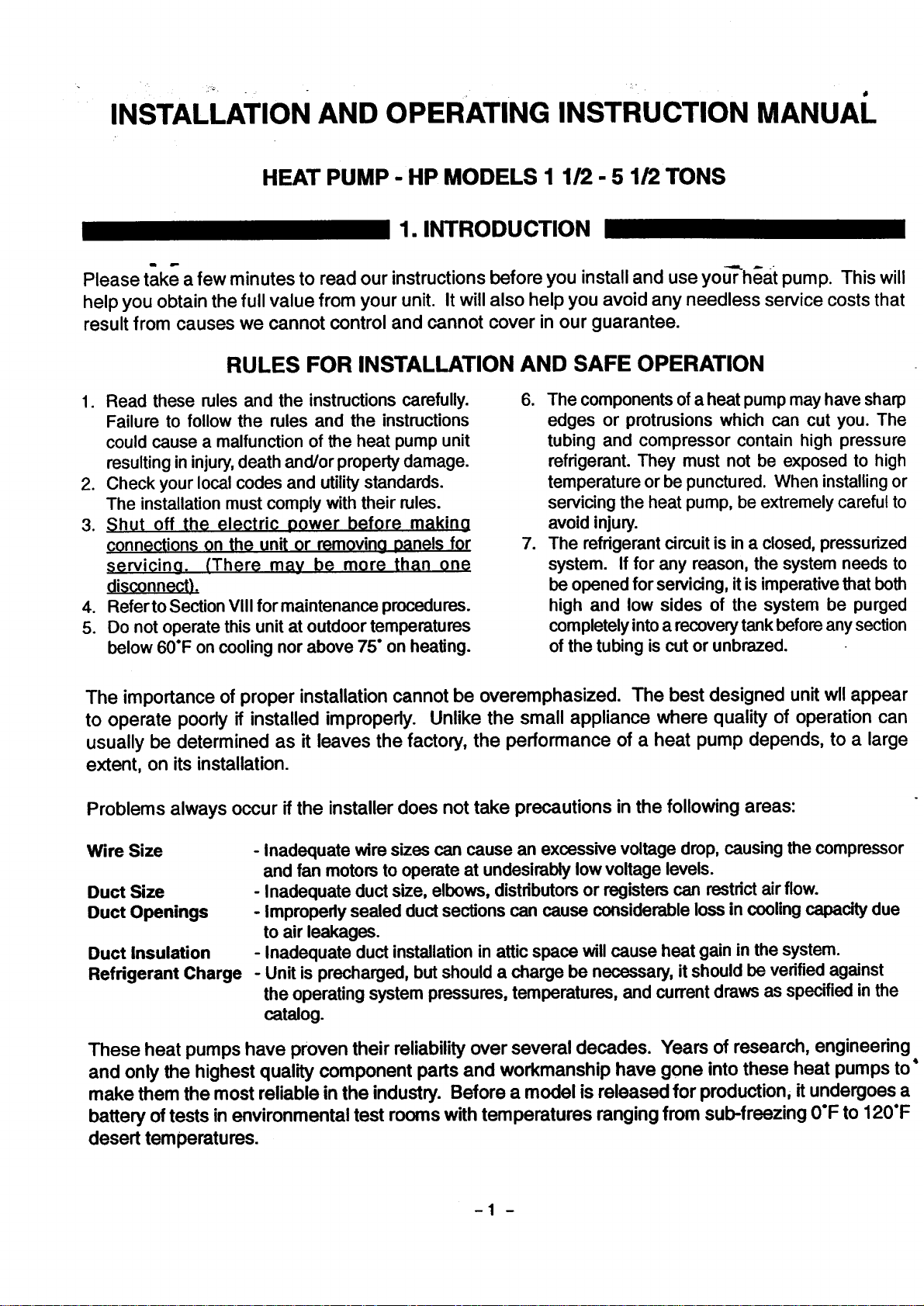
Please take a few minutes to read our instructions before you install and use yonheat pump. This will
help you obtain the full value from your unit. It will also help you avoid any needless service costs that
result from causes we cannot control and cannot cover in our guarantee.
RULES FOR INSTALLATION AND SAFE OPERATION
1. Read these rules and the instructions carefully.
Failure to follow the rules and the instructions
could cause a malfunction of the heat pump unit
resultingin injury,death and/or propertydamage.
2. Check your local codes and utilitystandards.
The installation must comply with their rules.
3. Shut off the electric oower before makino
connections on the unit or removing 0anels for
servicing. (There may be more than one
di_;connect!.
4. Referto Section VIII for maintenance procedures.
5. Do not operate this unit at outdoor temperatures
below 60"F on cooling nor above 75° on heating.
6. The components of a heat pumpmay have sharp
edges or protrusions which can cut you. The
tubing and compressor contain high pressure
refrigerant. They must not be exposed to high
temperature or be punctured. When installingor
servicing the heat pump, be extremely careful to
avoid injury.
7. The refrigerant circuitis in a closed, pressurized
system. If for any reason, the system needs to
be opened for servicing, it is imperative that both
high and low sides of the system be purged
completelyintoa recoverytank before anysection
of the tubing is cut or unbrazed.
The importance of proper installation cannot be overemphasized. The best designed unit wll appear
to operate poorly if installed improperly. Unlike the small appliance where quality of operation can
usually be determined as it leaves the factory, the performance of a heat pump depends, to a large
extent, on its installation.
Problems always occur if the installerdoes not take precautions in the following areas:
Wire Size
Duct Size
Duct Openings
Duct Insulation
Refrigerant Charge
- Inadequate wire sizes can cause an excessive voltage drop, causing the compressor
and fan motors to operate at undesirably low voltage levels.
- Inadequate duct size, elbows, distributorsor registers can restdctair flow.
- Improperly sealed ductsections can cause considerable loss in coolingcapacity due
to air leakages.
- Inadequate duct installationin attic space will cause heat gain in the system.
- Unit is precharged, but should a charge be necessary, it should be verified against
the operating system pressures, temperatures, and current draws as specified in the
catalog.
These heat pumps have proven their reliability over several decades. Years of research, engineering
and only the highest quality component partsand workmanship have gone intothese heat pumps to"
make them the mostreliable inthe industry. Before a model is released for production,it undergoesa
battery of testsin environmental test rooms withtemperatures rangingfrom sub-freezing 0°F to 120°F
desert temperatures.
-1 -
II. DIMENSIONS
• k
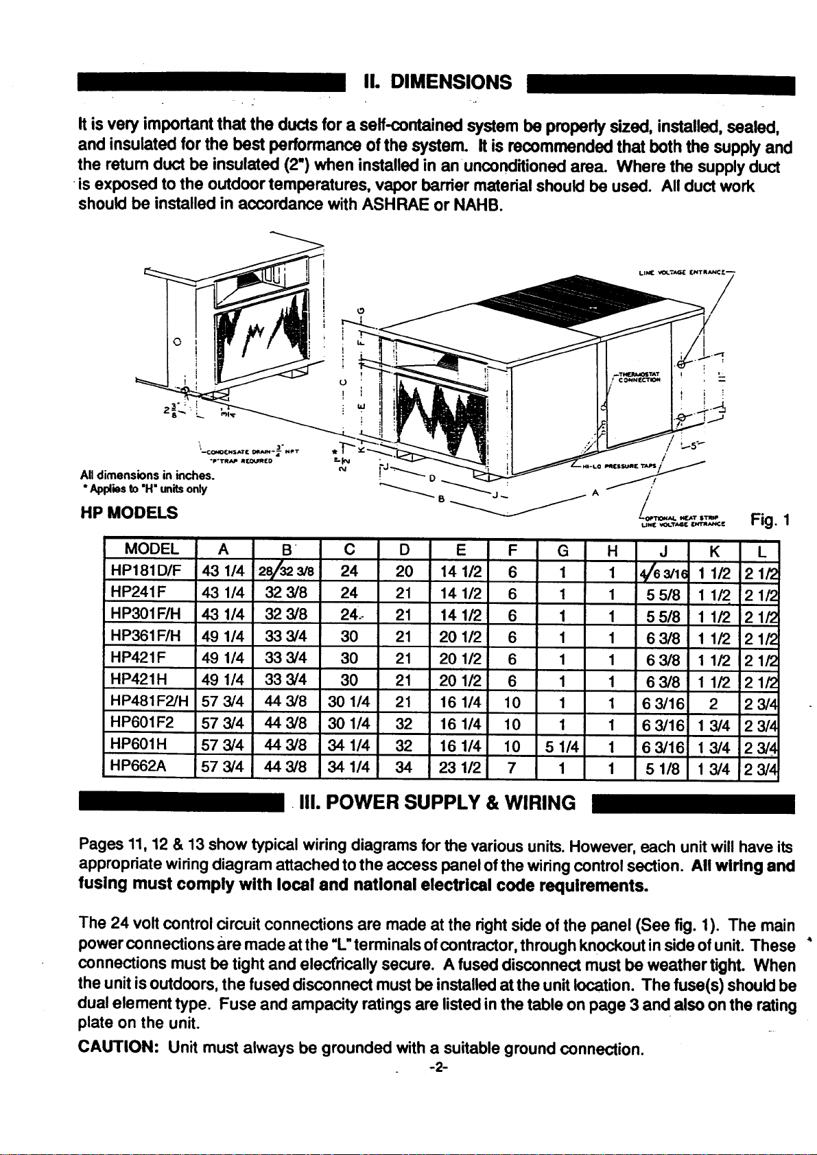
It is very important that the ducts for a serf-contained system be properly sized, installed,sealed,
and insulated for the best performance of the system. It is recommended that boththe supplyand
the retum duct be insulated (2") when installed in an unconditionedarea. Where the supplyduct
is exposed to the outdoor temperatures, vapor barrier material should be used. All duct work
shouldbe installed in accordance with ASHRAE or NAHB.
I
I
/
HP MODELS
MODEL A B C D E
HP181D/F 43 1/4 28/323/8 24 20 14 1/2
HP241F 43 1/4 32 3/8 24 21 14 1/2
HP301F/H 43 114 32 3/8 24.- 21 14 112
HP361F/H 49 1/4 33 3/4 30 21 20 1/2
HP421F 49 1/4 33 3/4 30 21 20 1/2
HP421H 49 1/4 33 3/4 30 21 20 1/2
HP481F2/H 57 3/4 44 3/8 30 1/4 21 16 1/4
HP601F2 57 3/4 44 3/8 30 1/4 32 16 1/4
HP601H 57 3/4 44 3/8 34 1/4 32 16 1/4
HP662A 57 3/4 44 3/8 34 114 34 23 112
F G H J K L
6 1 1 4/63/1( 1 112
6 1 1 55/8 11/2 !21/2
6 1 1 55/8 11/2 21/2
6 1 1 63/8 11/2 21/2
6 1 1 63/8 11/2 21/2
6 1 1 63/8 11/2 21/?
10 1 1 63/16 2 23/4
10 1 1 63/16 13/4 23/4
10 51/4 1 63/16 1 3/4 23/4
7 1 1 51/8 13/4 23/4
Fig. 1
2 1/2
i
_lJ. III. POWER SUPPLY & WIRING
Pages 11, 12 & 13 show typical wiring diagrams for the various units. However, each unit will have its
appropriate wiring diagram attached to the access panel of the wiring control section. All wiring and
fusing must comply with local and national electrical code requirernents.
The 24 volt control circuit connections are made at the rightside of the panel (See fig. 1). The main
powerconnections are made at the "L"terminals ofcontractor, through knockoutinside ofunit. These
connections must be tightand elect'ricallysecure. A fused disconnect must be weather tight. When
the unit isoutdoors,the fused disconnect mustbe installedat the unit location. The fuse(s) shouldbe
dual element type. Fuse and ampacity ratingsare listedinthe table on page 3 and also on the rating
plate on the unit.
CAUTION: Unit must always be grounded with a suitable ground connection.
-2-
ELECTRICAL DATA AT 230V
MODELNUMBER I I I H O,F I I I I
Compressor
-OL1tdoor
Motor
Indoor
Motor
Full Load
J_ps'
Full Load
,a_ps,
UnitTotaJ
MaximumFuseSize,Amps
MinimumCircuitAmpacity
i Based on UL operating conditions.
1Ph
3Ph
1Ph
3 Ph
1 Ph
3 Ph
1 Ph
3 Ph
1Ph
3Ph
1Ph
3 Ph
1 Ph
3 Ph
° Data appliesto230V.Unit operatesat 208/230V. "* 460V unitsavailableon specialorder.
= Check nameplate- maybe sllghUydifierer_withalternatecompressor.
47
9.9
.8
1.1
11.8
20
14.3
62.5 76/76
11.5 12.4/12.4
.8 1.2/1.2
1.3 1.4/1.4
13.6 15.0/15.9
. .
25 30/30
. o
16.5 18.1/18.1
°
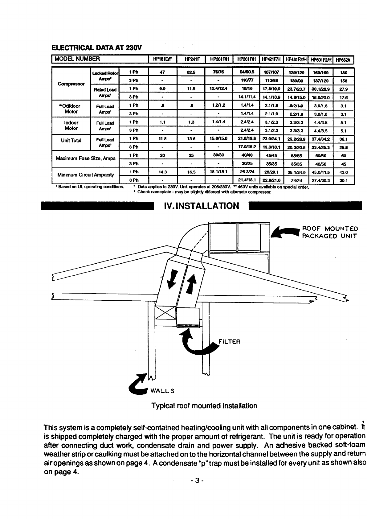
IV. INSTALLATION
94/00.5 107/107 129/129 169/169 180
.
.
110/T/ 110/88 130/99 137/129 158
18/16 17.8/19.9 23.7/23.7 30.1/28.9 27.9
14.1/11.4 14.1/13.9 14.8/15.0 16.0/20.0 17.6
1.4/1.4 2.1/1.9 _ --1 3.0/1.8 3.1
1.4/1.4 2.1/1.9 2.2/1.9 3.0/1.8 3.1
2.4/2.4 3.1/2.3 3.3/3.3 4.4/3.5 5.1
2.4/2.4 3.1/2.3 3.3/3.3 4.4/3.5 5.1
21.8/19.8 25.0/24.1 25.2/28.9 37.4/34.2 36.1
17.9/15.2 19.3/18.1 20.3120.5 23.4/25.3 25.8
40/40 45/45 55/55 60/60 60
30/25 35/35 35/35 40/50 45
26.3/24 28/29.1 35.1/34.9 45.0/41.5 43.0
21.4/18.1 22.8/21.6 24124 27.4/30.3 30.1
/
/
FILTER
WALL S
Typical roof mounted installation
ROOF MOUNTED
PACKAGED UNIT
This system is a completely self-contained heating/cooling unit with all components in one cabinet. It
isshipped completely charged with the proper amount of refrigerant. The unitis ready for operation
after connecting duct work, condensate drain and power supply. An adhesive backed soft-foam
weather strip or caulking must be attached on to the horizontal channel between the supply and return
air openings as shown on page 4. A condensate "p"trap must be installed for every unit as shown also
on page 4.
-3-
 Loading...