

- 1 -
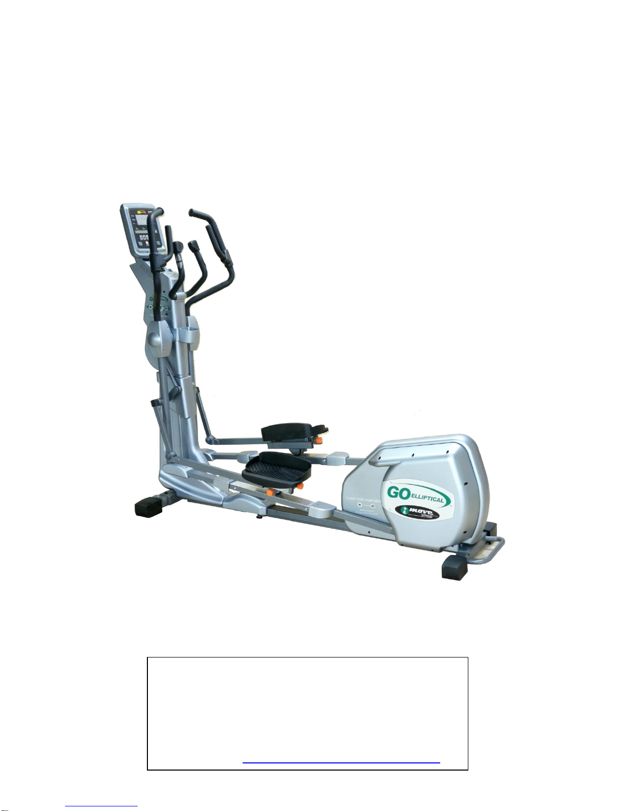
USER’S MANUAL
LX-03
USER WEIGHT LIMITATION: 300lbs(136kgs).
SERIAL NUMBER (found on frame):
USA
For Customer Service
1-267-808-3999
Email: cs@go-elliptical.com

- 2 -
Dear User,
Your GO Elliptical machine - Each machine shipped in Two Boxes Carton No. 1 is the main machine body and
Carton No. 2 is the Per-assembled top post with the whole VST (Variable Stride length system)
Pre-assembled, machine now will be very easy and simple to put together Suggest you get a second partner to
assemble the machine together We are sure you will be able to put the machine together with ease and enjoy The
new World-wide Real VST unit with us.
Read the manual and there is no need to assemble any of the VST Part by you any longer!!

- 3 -
PREASSEMBLY
For future service or related questions:
Please staple your receipt and/or write in the name and phone number of the retail store where you purchased your item.
Name: ______________________________ Phone Number: ___________________ Receipt: ______________________
Open the boxes:
You are now ready to open the boxes of your new equipment. Make sure to inventory all of the parts that are included in the boxes.
Check the Parts List for a full count of the number of parts included for this product to be assembled properly. .
Gather your tools:
Before starting the assembly of your unit, make sure that you have gathered all the necessary tools you may require to assemble the
unit properly. Having all of the necessary equipment at hand will save time and make the assembly quick and hassle-free.
Clear your work area:
Make sure that you have cleared away a large enough space to properly assemble the unit. Make sure the space is free from
anything that may cause injury during assembly. After the unit is fully assembled, make sure there is a comfortable amount of free
area around the unit for unobstructed operation.
Invite a friend:
Some of the assembly steps may require heavy lifting. It is recommended that you obtain the assistance of another person when
assembling this product.
User Weight Limitation:
Please note that there is a weight limitation for this product. If you weigh more than 300lbs. it is not recommended that you use this
product. Serious injury may occur if the user’s weight exceeds the limit shown here. This product is not intended to support users
whose weight exceeds this limit.
For Customer Service
1-267-808-3999
Email: cs@go-elliptical.com
- 4 -
POWER REQUIREMENTS
Power Requirements:
IMPROPER CONNECTION OF THE EQUIPMENT GROUNDING CONNECTOR CAN RESULT IN THE RISK OF AN ELECTRIC
SHOCK. CHECK WITH A QUALIFIED ELECTRICIAN OR SERVICE MAN IF YOU ARE IN DOUBT AS TO WHETHER THE
PRODUCT IS PROPERLY GROUNDED. DO NOT MODIFY THE PLUG PROVIDED WITH THE PRODUCT, IF IT WILL NOT FIT
THE OUTLET; HAVE A PROPER OUTLET INSTALLED BY A QUALIFIED ELECTRICIAN.
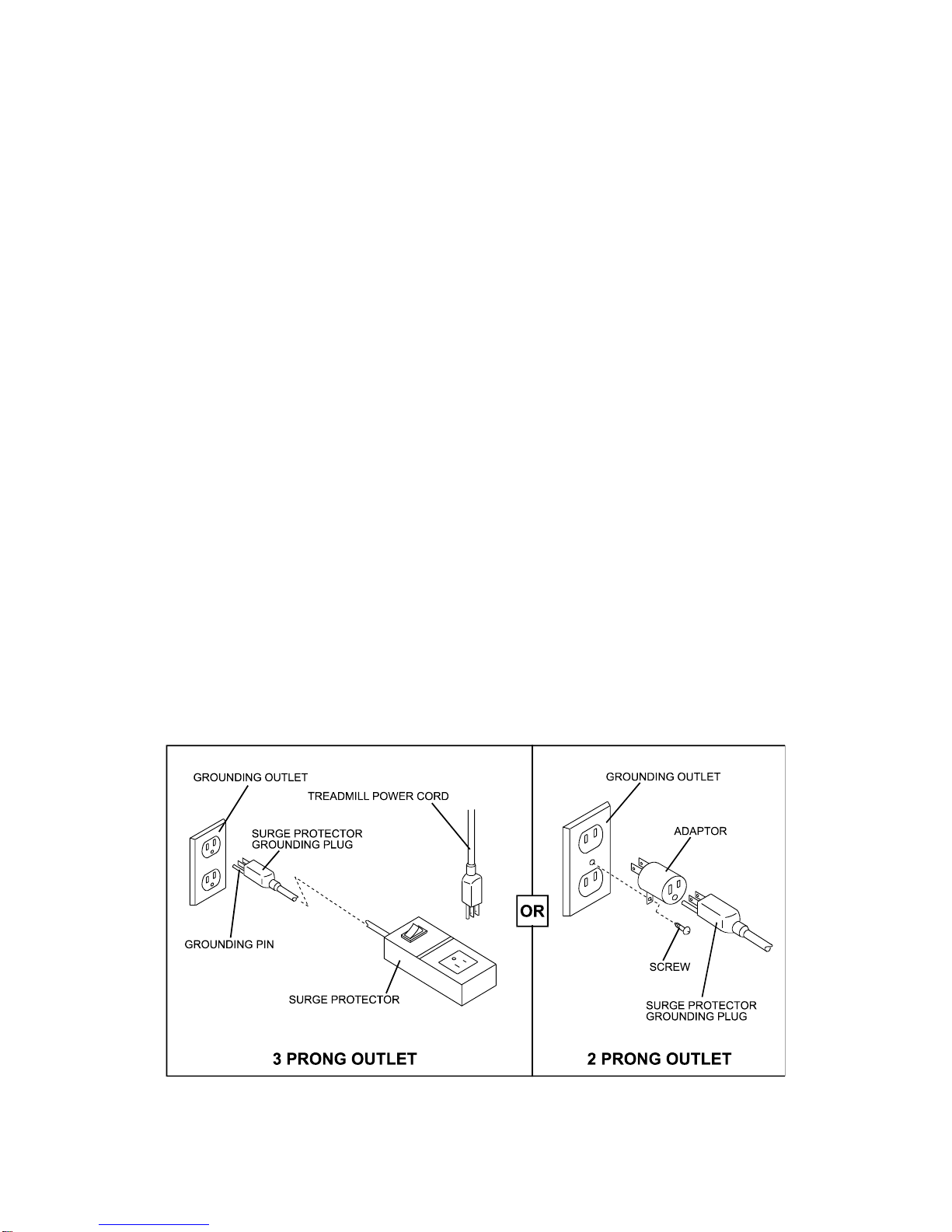
This treadmill can be seriously damaged by sudden voltage changes in your home’s electrical power. Voltage spikes, surges and
noise interference can result from weather conditions or from other appliances being turned on or off. To reduce the possibility of
treadmill damage, always use a surge protector (not included) with your treadmill.
Surge protectors can be purchased at most hardware stores. The manufacturer recommends a single outlet surge protector with a
UL 1449 rating as a Transient Voltage Surge Suppressor (TVSS) with a UL suppressed voltage rating of 400V or less and an
electrical rating 120VAC, 15 amps.
This treadmill must be grounded to reduce the risk of electrical shock. Grounding provides a path of least resistance for electric
current, should the treadmill malfunction. This treadmill is equipped with an electrical cord that has an equipment-grounding
conductor and a grounding plug. Always plug the power cord into a surge protector, and plug the surge protector into an
appropriate outlet that is properly installed and grounded in accordance with all local codes and ordinances.
This product is for use on a nominal 120-volt circuit, and has a grounding plug that looks like the plug illustrated in the drawing below.
GFCI outlets and GFCI / AFCI Circuit Breakers are NOT recommended for use on this product. GFCI outlets and GFCI / AFCI Circuit Breakers may cause this
equipment to function improperly.
- 5 -
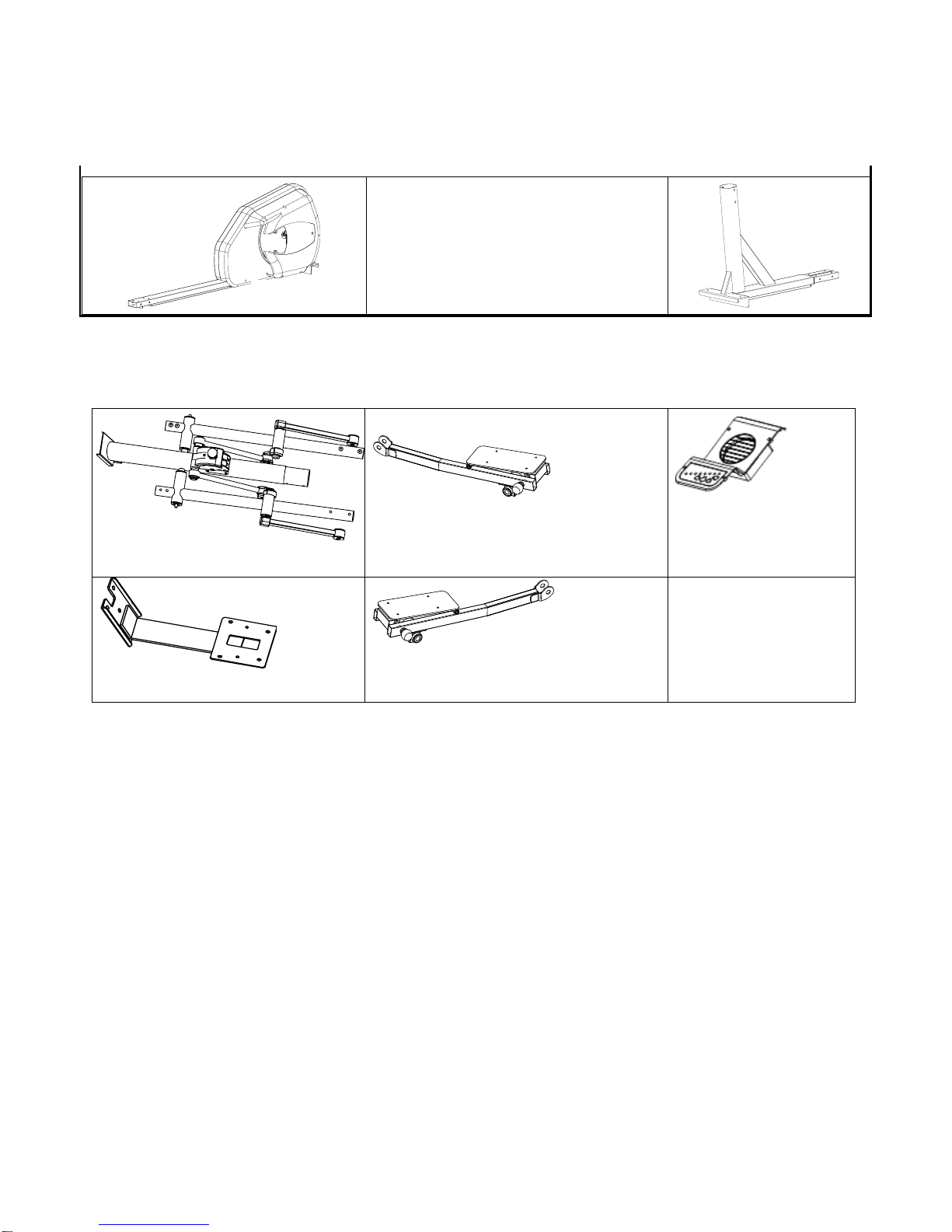
SUPPLIED COMPONENTS BOX 1
SUPPLIED COMPONENTS BOX 2
SUPPLIED COMPONENTS BOX 3
Base Frame
Base Frame
Pedal Support Tube (L)
Pedal Support Tube (R)
Console Base
Fan/VST Board
Upright Tube
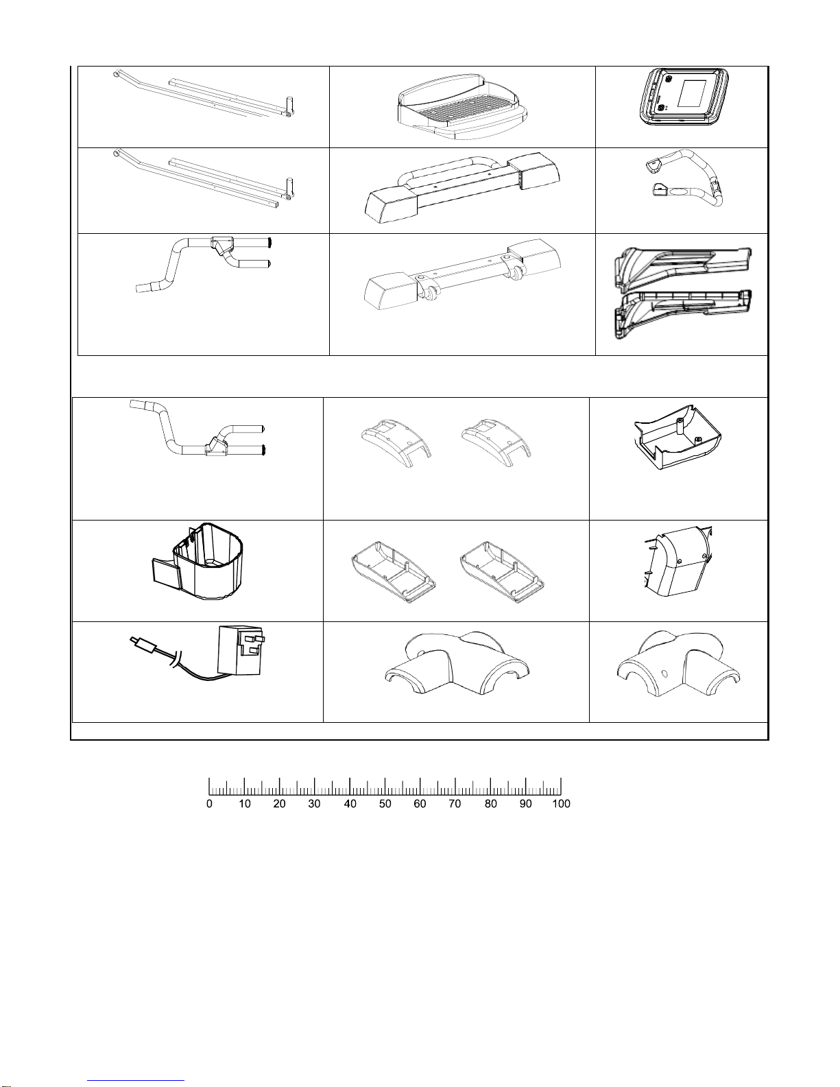
- 6 -
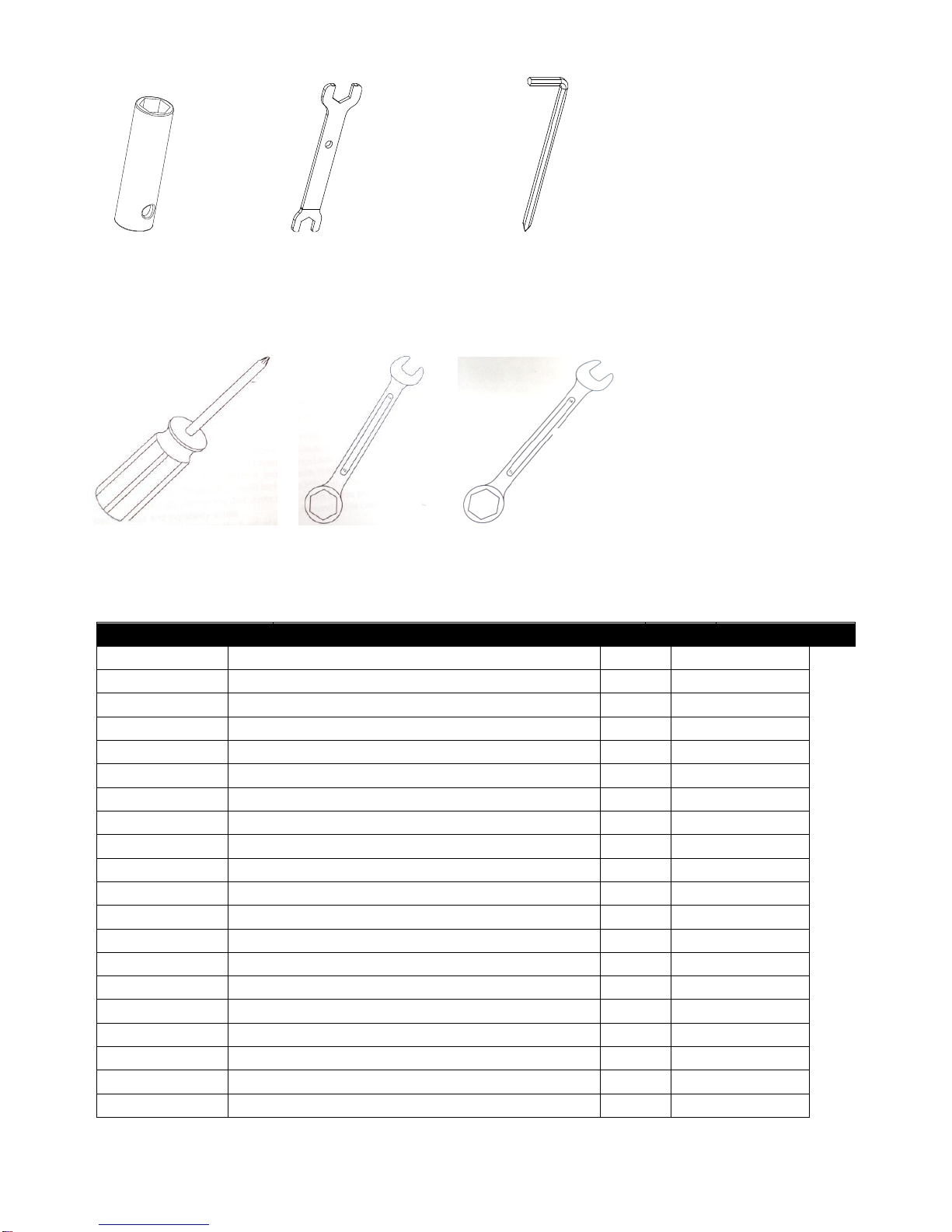
TOOL included with machine:
Action Handlebar (L)
Power pack
Action Arm Cover Front
Pedal Support Tube Top (L/R)
Pedal Support Tube Bottom (L/R)
Action Arm Cover Rear
Console Base Cover Rear
Water Bottle Holder
Console Base Cover
Rear
Pedal Support Tube (L)
Pedal (L/R)
Console
Pedal Support Tube (R)
Rear Stabilizer
Fixed Handlebar
Front Stabilizer
Action Handlebar (R)
Lower Upright Post Cover (L&R)
MILLIMETERS
- 7 -
General tools prepared by user:
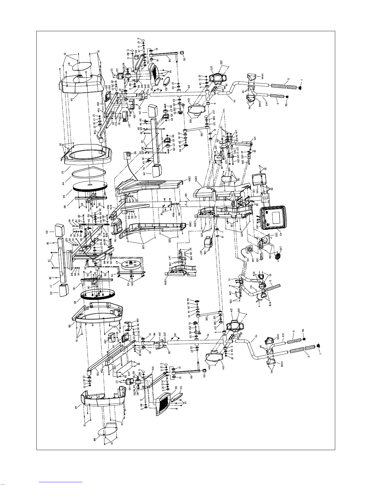
COMPLETE PARTS LIST
Item No.
Description
Qty.
Part No.
1
Handlebar end cap
2
CE90-1
2
Handlebar grip
2
CE90-2
3
T-Bar grip 2 CE90-3
4
Hand pulse grip unit
2
CE90-4
5
Protective cap
4
CE90-5
6
Screw M8*1.25*15
2
CE90-6
7
Locking washer
2
CE90-7
8
Washer ∮25.4
2
CE90-8
9
Sleeve O.D. 25.4MM
4
CE90-9
10
Sleeve 8 CE90-10
11
Washer 10*32*2T
6
CE90-11
12
NY lock nut M10*1.5
9
CE90-12
13
Pedal tube shaft ∮17*70mm
2
CE90-13
14
Pedal tube shaft ∮17*97mm
2
CE90-14
15
Bearing 2203RS
4
CE90-15
16
Retainer R40
4
CE90-16
17
Washer 10*22*3T
2
CE90-17
18
Allen head bolt M8*1.25*15
38
CE90-18
19
Screw M8*1.25*72
4
CE90-19
20
NY lock nut M8*1.25
10
CE90-20
M8 socket
M8/M10
wrench
Screw driver 5mm
M8 wrench
M10 wrench
Screw driver 5mm

- 8 -
21
Plastic cap 5/16
4
CE90-21
22
Large square plastic cap
2
CE90-22
23
Rear foot cover
2
CE90-23
24
Front foot cover (middle)
2
CE90-24
25
Left roller holder
1
CE90-25
26
Right roller holder
1
CE90-26
27
Wheel 2 CE90-27
28
Screw M8*50
2
CE90-28
29
Screw M4*16mm
6
CE90-29
30
Screw M5*0.8*12
16
CE90-30
31
Screw M5*20
29
CE90-31
32
Screw M4*8
8
CE90-32
33
Bearing 6003
2
CE90-33
34
Bearing ∮17mm
4
CE90-34
35
Screw M6*15
1
CE90-35
36
Locking screw M8*1.25*30
1
CE90-36
37
Spacer 17*28*1.0
8
CE90-37
38
Screw M8*1.25*65
6
CE90-38
39
Washer 8*25mm
20
CE90-39
40
Screw M8*1.25*30
1
CE90-40
41
Nut M8 3 CE90-41
42
Spring 3.5mm*21mm
1
CE90-42
43
Console 1 CE90-43
44
P.U.Roller
2
CE90-44
45
Screw M5*15
4
CE90-45
46
Plastic flat round cap
2
CE90-46
47
Flywheel 250
1
CE90-47
48
Speed Sensor Cable
1
CE90-48
49
Belt 550 J6
1
CE90-49
50
Tool storage cover
1
CE90-50
51
Plastic flat round cap
2
CE90-51
52
Pedals 2 CE90-52
53
Pedal bracket
2
CE90-53
54
Adjustable foot
2
CE90-54
55
Small square plastic cap
2
CE90-55
56
End cap (T-Bar)
2
CE90-56
57
Rear cover left
1
CE90-57
58
Rear cover right
1
CE90-58
59
Outer rear cover left
1
CE90-59
60
Outer rear cover right
1
CE90-60
61
Screw M3*10mm
1
CE90-61
62
Motor 1 CE90-62
63
D- Axle ∮15**182mm
1
CE90-63
64
Magnet ∮14.8*7L
1
CE90-64
65
Washer 5/16*16*1.0
4
CE90-65

- 9 -
66
Pulley 2 CE90-66
67A
Base frame
1
CE90-67A
67B
Main frame
1
CE90-67B
68
Upright tube
1
CE90-68
69
Swivel tube, LH
1
CE90-69
70
Swivel tube, RH
1
CE90-70
71
Fixed handle bar
1
CE90-71
72
Handle bar, LH
1
CE90-72
73
Handle bar, RH
1
CE90-73
74A
Left pedal arm front
1
CE90-74A
74B
Left pedal arm rear
1
CE90-74B
75A
Right pedal arm front
1
CE90-75A
75B
Right pedal arm rear
1
CE90-75B
76
Front foot ( Stabilizer )
1
CE90-76
77
Rear foot ( Stabilizer )
1
CE90-77
78
Flywheel holder bracket
1
CE90-78
79
Belt tensioner
1
CE90-79
80
Metal cross, LH
1
CE90-80
81
Metal cross, RH
1
CE90-81
82
NY lock nut M12
6
CE90-82
83
Retainer R12
2
CE90-83
84
Metal plate
2
CE90-84
85
Roller axle ∮12**103mm
2
CE90-85
86
Connecting tube
2
CE90-86
87
Left decorative cover
1
CE90-87
88
Right decorative cover
1
CE90-88
89
Console cable 990MM
1
CE90-89
90A
Cable 1300MM
1
CE90-90A
90B
Main cable top
1
CE90-90B
91
Power wire 750MM
1
CE90-91
92
Power ADAPTOR
1
CE90-92
93
Washer ∮17*∮12*T1.0
3
CE90-93
94
Washer ∮35*∮12*T2.0
1
CE90-94
95
Washer ∮35*∮6*T2.0
1
CE90-95
96
Bearing 6001
6
CE90-96
97A
Toggle switch left
1
CE90-97A
97B
Toggle switch right
1
CE90-97B
98
Square moving arms (L)
1
CE90-98
99
Square moving arms (R)
1
CE90-99
100
Long connecting bar
2
CE90-100
101
Swinging axle plate
2
CE90-101
102
Second pedal support tube left
1
CE90-102
103
Second pedal support tube right
1
CE90-103
104
Step foot cover-Top
2
CE90-104
105
Step foot cover-Bottom
2
CE90-105

- 10 -
106
Decorative front cover for left step tube
1
CE90-106
107
Decorative rear cover for left step tube
1
CE90-107
108
Decorative front dover for right step tube
1
CE90-108
109
Decorative rear cover for right step tube
1
CE90-109
110
Roller cover
2
CE90-110
111
Screw M5*8
3
CE90-111
112
Bearing 6002
4
CE90-112
113
Aluminum rail
2
CE90-113
114
Axle for inner adjustor
1
CE90-114
115
Base for inner adjustor
1
CE90-115
116
Outer adjustor
1
CE90-116
117
Connecting axle for lift motor
1
CE90-117
118
Holder for lift motor
2
CE90-118
119
Adjustor connector
2
CE90-119
120
Hex head screw M10×70mm
1
CE90-120
121
Lift motor
1
CE90-121
122
Screw M4*16
24
CE90-122
123
Arm cover front
2
CE90-123
124
Arm cover rear
2
CE90-124
125
Base bracket for lift motor
1
CE90-125
126
Hex head screw M10×40mm
1
CE90-126
127
Bottle holder
1
CE90-127
128
Vest control board
1
CE90-128
90B
Main cable top
1
CE90-90B
129
380 Pulley rim
2
CE90-129
130A
Upright post cover
1
CE90-130A
130B
Upright post cover
1
CE90-130B
131
Console base
1
CE90-131
132B
Right upper upright post cover
1
CE90-132B
133
Front computer cover
1
CE90-133
134
Front cover
1
CE90-134
135
Screw M4*16mm
11
CE90-135
136
Screw M4*16mm
8
CE90-136
137
Adjustor end cap
2
CE90-137
138
Large adjustor screw M10
2
CE90-138
139
Fan network
1
CE90-139
140
FAN 1 CE90-140
141
Cable for Fan
1
CE90-141
142
Fan and vest control board
1
CE90-142
143
Inner small handlebar
2
CE90-143
144A
Handlebar cover front
2
CE90-144A
144B
Handlebar cover rear
2
CE90-144B
145
Rear console base cover
1
CE90-145
146
Adjustor guide cover
2
CE90-146
147
Adjustor fixed cover
2
CE90-147

- 11 -
148
Adjustor rod cover
8
CE90-148
149
Tablet holder
1
CE90-149
150
Screw M8*105
4
CE90-150
#A
Washer M8
4
CE90-#A
- 12 -
- 13 -
ASSE ASSEMBLY
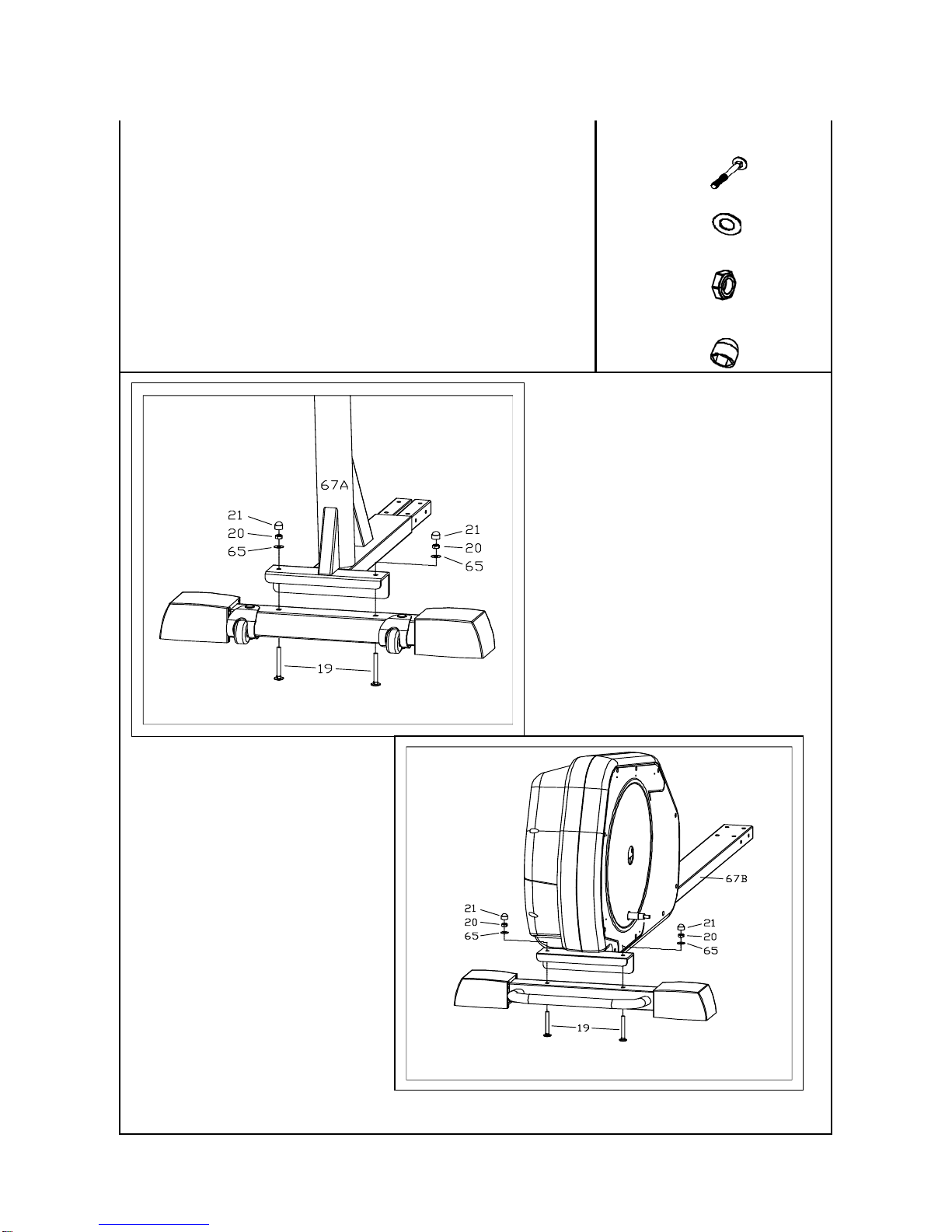
STEP 1: Attach the Front Support (Front Stabilizer)
NOTE: To make attaching the support easier place a large
Styrofoam block under the machine.
(A) Attach the front support to the base frame with the wheels facing
outward.
(B) Align the 2 bolt holes in the front support with the bolt holes in the
main frame.
(C) Secure the front support to the main frame by using 2 x #19 bolts
inserted through the bottom, 2 x # 65 washers 2 x 20 lock nuts and
2 x #21 nut covers
(D) Tighten all bolts now.
#19
4
#65
4
#20
4
#21
4
- 14 -
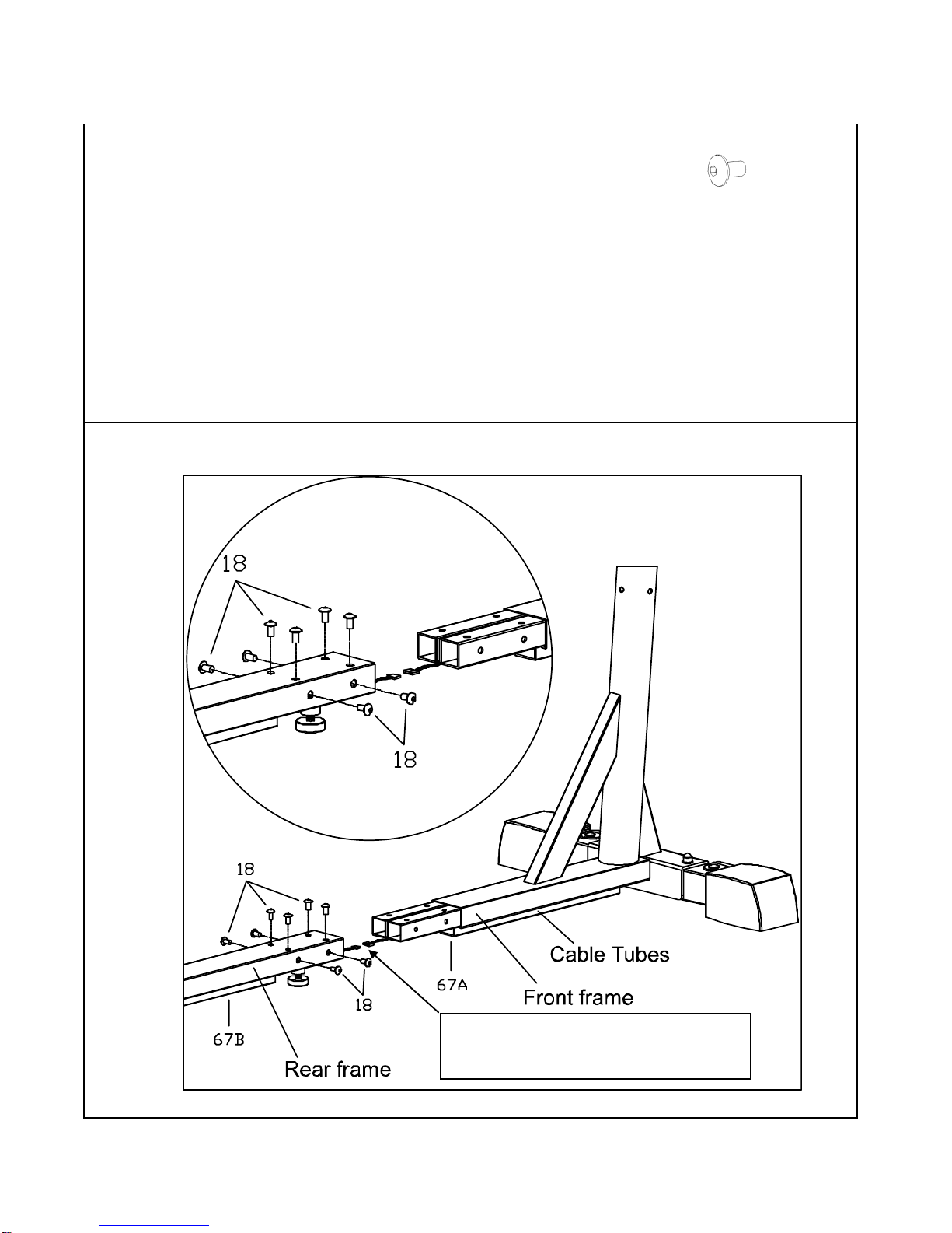
STEP 2: Attach the Base Frame to the Main Frame
NOTE: Caution: Pinch Point Warning Do Not Pinch the Data Cables
Between the Frames. Keep Hands Clear.
(A) Place the base frame flat on the ground in front of the base frame.
(B) Slide the base frame connecting tube inside the main frame connector
tube
(C) Align the main frame bolt holes with the base frame threaded holes and
hand tighten all eight #18 bolts.
(D) Once all eight #18 bolts are inserted, use the Allen wrench to fully tighten
all the bolts.
(E) Now connect the computer cable extending from the main frame to the
cable extending from the base frame.
(F) Insert any extra cable length back in to the frame.
#18 8
Caution: Pinch Point. Do not pinch the data
cables or fingers between the two frames.
- 15 -
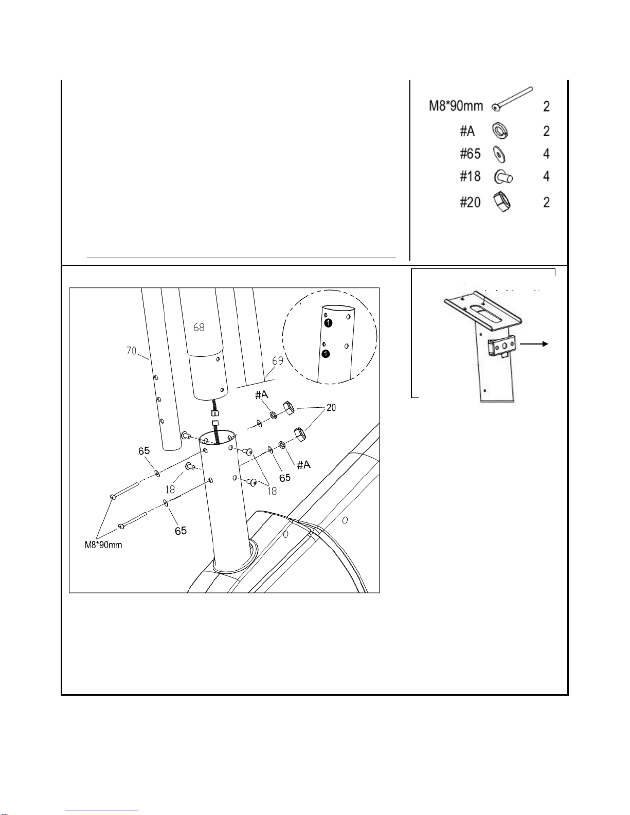
STEP 3: Attach the Upright Tube Assembly to the Base Frame
NOTE: This step is easier to complete with 2 people
! Caution Pinch Point: Do not pinch the wires between the frame!
(A) Hold the upright tube over the round base frame tube so that the data
cable can be connected prior to assembly
(B) After the data cable is connected slide the upright tube onto the round
base frame tube.
(C) Check to make sure the upright tube is facing the correct direction. (See
Fig. 4A)
(D) Secure the upright tube to the base frame by using 6 x #18 Allen head
bolts.
(E) Hand tighten all the bolts first Do not fully tighten these bolts until step 9.
Facing towards the
Fig 4A
- 16 -
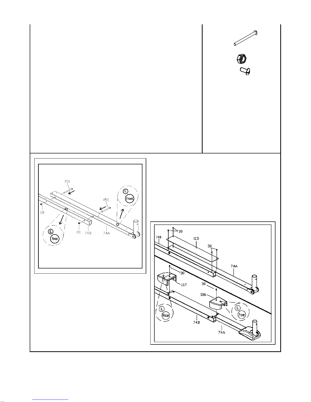
STEP 4: Assembling the Pedal Tubes
(A) Place both the left pedal tubes #74A and #74B on a flat surface.
(B) Secure the two pedal tubes together by using 2x #150 bolts and 2 x #20
Nylock nuts. (See Fig. 7A)
(C) Repeat the process for the right side pedal tube by using the right pedal
tubes #175A and 175B
(D) Tighten all bolts now.
(E) Place the aluminum rail #133 on top of the left pedal tubes and align the
bolt holes on the aluminum rail with the bolt holes on the pedal tube.
(F) Secure the aluminum rail to the pedal tubes by using 4x#30 screws. See
(Fig. 7B)
(G) Tighten all the bolts now.
(H) Repeat the process for the left side pedal tube
(I) Place the front and rear decorative covers #106 and #107 over the
aluminum rail bolts and secure them by using 2x#30 screws
(J) Repeat this process for the right side.
(K) Tighten all bolts now
#150
4
#20
4
#30
12

- 17 -
STEP 5: Attach the Pedal Tube Assembly to the Main Frame
(A) Attach the front pedal covers top and bottom #104/#105 to the left pedal
(this was assembled in the prior step) tube by using 2x #122 screws and 1
x #30 screw. (See Fig.8A)
(B) Repeat the process for the right side pedal tube
(C) Locate the left Pedal tube. NOTE: the left and right pedal tubes are
different and the machine will not function if the wrong pedal tube is
assembled to the wrong side.
(D) Attach the left pedal tube to the base frame pulley axel(See Fig.8B)
(E) Secure the left pedal tube to the base frame crank arm by using 1 x #17
washer and 1 x #12 M10 lock nut. Completely tighten with a wrench
(F) Repeat the process for the right side pedal tube
(G) Insert the front left of the pedal tube #86 in to Action handle bar tube #69
and secure them together by using 2 x #18 Allen head bolts (See Fig. 8C)
Do not fully tighten these bolts. These should be tightened in step 11
(H) Repeat the process for the right side. Do not fully tighten these bolts.
#122
4
#30
2
#12
2
#17
2
#18
4
Make sure both square moving Arm ( 98,and 99) toward the down direction, if
for any reason you have rotated the Swivel tube (l /R ) to occur the 98/99 arms
one of them towards up--just turn the Swivel tube 360 degree to make both
Moving towards to same down direction.
Wrong
Correct

- 18 -
STEP 6:Attach the Second Pedal Support Tube Assembly
(A) Place the left second pedal support tube assembly on top of the pedal
support tube and align the rubber roller on the center of the #113
aluminum rail.
(B) Insert the “U” bracket over the preassembled #98 short square swing
arm
(C) Insert the small axel #14 through the second pedal support tube #102 “U”
bracket and the short square swing arm #98
(D) Secure the small axel #14 by using 2 x #11 washers and 2 x #12 lock nuts.
(E) Completely tighten the large bolts and cover with 2 x #5 protective caps
(F) Repeat the process above for the right side.
NOTE: Due to the tight tolerance of part #102 and #98 it may be
easier to install put part #11 washer and #12 nut on one side of
the # 14 small axel and twist the axel through the part #102 and
#98.
#12 4
#5 4
#14 2
#11 4
Second pedal support tube (left)

- 19 -
STEP 7:Roller Alignment
(A) check with both Alum Rail there are Two of soft PP Bars attach to each
side of each Rail .Set both PU roller To the center of each the soft pp bars
in case any of the Roller will not be able to total set to the center of the
Rails Simply as photo 3 shown hold both of the handlebars (#72 and #73 )
as photo shown move both habdlebars together from side to Side to
make sure the Roller are set in the center of the alignment PP bars with
ease . if not, check with the Screws that suppose to Tightened with finger
tighten if some are tightened too much With assembly steps 3, 4, and
7 , (if not loose them a little ) Make sure all screws are in loose condition
and the Roller Will be set in the center of the pp Bars with ease After
Roller set then tighten up all screws ( #18) in Step 3, 4, and 7, firmly Also
the long Screw (M8 X 90 mm + nut ) tightened up as well.
(B) after all screws tightened up and PU Roller well set , pill off all four
soft PP bars at both side of each PU Roller Will not need these soft
PP bars anymore
12
1 2 4 5 6

- 20 -

- 21 -
STEP 8:Attach the Console Base, Upright Covers and Handlebars
(A) Place the console base #131 on top of the upright tube #68 and align the
bolt holes (See Fig. 8A)
(B) Secure the console base to the upright tube by using 3 x #18 Allen bolts.
Completely tighten the bolts now
(C) Attach and secure the handle bars to the handle bar bracket on the upright
tube by using 2 x #6 Allen head bolts. Completely tighten the bolts (See
Fig 8C) Tighten the handlebar bolts now.
(C) Place the handlebar cover over the handlebar bolts and secure it to the
upper upright post covers by using 2 x #136 screws.
#18 3
#6 2
#134 1
#136 2
Fig 8A
Fig 8C

- 22 -
STEP 9: Attach the Fan and Handlebar Covers
(A) Place the fan cover #133 in-between the #132A and #132B covers (See Fig.9A).
(B) Take the fan wire and route it with the other wires from the handrail assembly
(C) Secure the fan cover #133 by using 4 x #136 screws.
#136
4
Fig.9A

- 23 -
STEP 10:Attach the Console and Covers
CAUTION: DO NOT PINCH THE POWER WHIRE BETWEEN THE PLASTIC
COVERS BE CERTAIN TO CENTER THE POWER WIRE CONNECTOR
BETWEEN THE COVERS
Place the lower upright post covers #130A/B around the upright post (See Fig.
10A). 10A-1,10A-2,10A-3
How to set the Lower front cover 130A and 130B See the figure Fig 10A , 10A-1, 10A-2
and 10A-3 As Fig 10A-1, Set the left Step foot tube toward to rear Of the machine to the
max. back position as the arrow Shown , insert the lower front cover with the direction As
arrow shown to the proper position to front post as Fig 10A-3 then do the same action to
set the right lower Front cover to the proper position , match up left/right Lower front
cover and secure both covers with Screws135.
Secure the two covers together by using 7 x #135 screws.
Attach the Tablet holder to the computer and secure it by using 2 x #30 Screws
(See Fig. 10B)
Connect the computer wires from the computer to the computer wires from the
upright post. Route the wires as directed in Fig. 9C. Push the extra wire down in to
the upright post covers or into the back of the computer (See Fig. 10C)
Secure the console to the console mounting bracket by using 4 x #30/E screws.
#135 7
#30 2

- 24 -
Fig. 10C
Fig. 10B
Fig. 10D
Due to console/computer will assemble with a higher Location of machine SUGGEST to have a
partner to Hold the computer and make sure all the Cable/plug Are plug in firmly or use a Chair
to stand on it to get a higher position to the console location so be more easier to make sure all
the cable /plug are plug in firmly.

- 25 -
Console –cables connecting instruction

- 26 -
STEP 11: Attach the Upper Action Handle Bars and Covers
(A) Place the left upper action handlebar #72 inside the left
lower action handlebar #69.
(B) Secure the left upper action handlebar to the left lower
action handlebar by using 2 x #18 Allen head bolt, 2x #65
flat washer and 2 x #A Spring lock washer (See Fig. 11A)
(C) Repeat the process above for the right side
(D) Completely tighten all bolts
(E) Place the front and back decorative covers #123and 124
around the left side lower action arm (the front and back
decorative covers will attach to the left and right side)
(F) Secure the covers with 4 x #122 screws
(G) Repeat the process above for the right side
#18
4
#65
4
#A
4
#122
8
Fig. 11A
Fig. 11B

- 27 -
STEP 12: Attach the Bottle Holder and Center Frame Cover
(A) Place the water bottle holder #136 on the upper upright cover #132A/B (See
Fig. 12A).and slide it downwards on to the mounting bracket, aligning the
screw holes.
(B) Secure the water bottle holder to the covers using 2 x # 136 screws.
Attach the base frame/main frame joint cover to the lower center frame support.
Align this cover with the lower upright cover and snap in place. This decorative
cover is also used to store the tools used for assembly.
#136
2
Fig. 12A
Fig. 12B

- 28 -
STEP 13: Attach the Rear Covers
HINT: USE THE LONGER SCREWDRIVER FOR THIS STEP
(A) Align the right outer rear cover screw holes with the inner
rear cover screw holes
(B) Secure the outer rear cover to the inner rear cover by using
7x #31 screws (See Fig. 13A)
(C) Repeat the process for the left side
(D) Completely tighten all bolts
(E) Place the rear decorative cover over the outer rear cover.
(F) Secure the rear decorative cover to the outer rear cover
using 3x #31 screws. (See Fig. 13B)
(G) Repeat the process above for the right side.
attached in outer rear cover
#31 6
Fig. 13A
Fig. 13B

- 29 -
STEP 14:Attach the Foot Pedals
NOTE: The left and right pedals are different. Please verify the correct
pedal for each side by the L and R sticker located on the pedals.
(A) Locate and attach the left pedal, to the second pedal support tube “foot
plate”.
(B) Secure the foot pedal to the foot plate by using 4x #18 Allen head bolts.
(C) Repeat the process for the right side.
#18
8

- 30 -
STEP 15:Power and Leveling
There are levelers under the front and middle of the elliptical. Turn the levelers clockwise
to lower the leveler and counter clockwise to raise the leveler. The elliptical must be
completely level to avoid excess shaking in the frame.

- 31 -
Mp3 and Cooling Fan (Power)
To play music or audio books through the console sound system while you exercise, plug the included
audio cable into the jack on the back of the console and into a jack on your MP3 or iPod; make sure that
the audio cable is fully plugged in. Next, press the play button on your MP3 player or IPOD. Adjust the
volume level using the volume control on your MP3 or IPOD
Cooling Fan (Power)
Cooling Fan available with the unit to increase the Air Circulation during exercise by turn the
“Cooling Fan” key ON or Press the Key again to TURN IT OFF..”
Please follow these instructions when carrying and moving the equipment about, because lifting it incorrectly
may strain your back or cause other incidents:
The device is easy to move by pulling it on the integrated transport wheels that are located on the front support.
Lift the device from the rear and pull the unit across the floor. We recommend that you use a protective floor
cover when transporting the equipment
To prevent the equipment from malfunctioning, store in a dry place with as little temperature variation as
possible and protected from dust.

- 32 -
VST STRIDE ADJUSTMENTADJUSTMENT:
The LX-03 is equipped with an electronic stride adjustment. This feature allows you to adjust the stride length to what
is most comfortable for you.
To adjust the stride, locate the VST adjustment buttons located on the Fan/VST board pictured below. The stride can be
adjusted during use, by pressing the + or – stride adjustment buttons. The elliptical has four different stride settings.
The LED indicator will illuminate the current stride setting.

- 33 -
MUSCLE CHART
Targeted muscle groups:
The exercise routine that is performed on this product will develop primarily lower body muscle groups. These muscle groups are
shown in gray color on the chart below.
A
Shoulder muscles
Calf muscles
B
Pectoral muscles
Trapezius muscles
H
C
Bicep muscle
Tricep muscles
I
D
Abdominal muscles
Back muscles
J
E
Forearm muscles
Gluteal muscles
K
F
Quadricep muscles
Hamstring muscles
L

- 34 -
STRETCHING ROUTINE
Warm up and cool down:
A successful exercise program consists of a warm-up, aerobic exercise, and a cool-down. Do the entire program at least two and preferably three times a week, resting for a
day between workouts. After several months, you can increase your workouts to four or five times per week.
Warming up is an important part of your workout, and should begin every session. It prepares your body for more strenuous exercise by heating up and stretching out your
muscles, increasing your circulation and pulse rate, and delivering more oxygen to your muscles. At the end of your workout, repeat these exercises to reduce sore muscle
problems. We suggest the warm-up and cool-down exercises on the following pages:
Toe Touch:
Slowly bend forward from your
waist, letting your back and
shoulders relax as you stretch
toward your toes. Reach down as
far as you can and hold for 15
counts.
Shoulder Lift:
Lift your right shoulder up toward
your ear for one count. Then lift
your left shoulder up for one count
as you lower your right shoulder.
Inner Thigh Stretch:
Sit with the soles of your feet
together with your knees pointing
outward. Pull your feet as close
into your groin as possible. Gently
push your knees towards the floor.
Hold for 15 counts.
Hamstring Stretch:
Sit with your right leg extended.
Rest the sole of your left foot
against your right inner thigh.
Stretch toward your toe as far as
possible. Hold for 15 counts.
Relax and then repeat with left leg
extended.
Side Stretch:
Open your arms to the side and
continue lifting them until they are
over your head. Reach your right
arm as far upward toward the
ceiling as you can for one count.
Feel the stretch up your right side.
Repeat this action with your left
arm.
Calf-Achilles Stretch:
Lean against a wall with your left
leg in front of the right and your
arms forward. Keep your right leg
straight and the left foot on the floor;
then bend the left leg and lean
forward by moving your hips toward
the wall. Hold, and then repeat on
the other side for 15 counts.
Head Roll:
Rotate your head to the right for
one count, feeling the stretch up the
left side of your neck. Next, rotate
your head back for one count,
stretching your chin to the ceiling
and letting your mouth open.
Rotate your head to the left for one
count, and finally, drop your head to
your chest for one count.

- 35 -
LX-03
Console Display Description
Display
Display Range
Setting Range
Default
Memory
SEX
MALE/ FEMALE
Yes
AGE
10 - 100
Yes
WEIGHT(METRIC)
20 - 330(Lb.)
10 - 150(KG)
Yes
HEIGHT
36 - 84(INCH)
90 – 210(CM)
Yes
TIME
0:00 - 99:59
0:00 - 99:00
0: 00
No
DISTANCE
0.0 - 99.99
0.00 - 99.50
0: 00
No
CALORIES
0 - 999
0 - 990
0: 00
No
SPEED
0.0 - 99.9
0: 00
No
PULSE
30 - 200 BPM
0: 00
No
RPM
0 - 250 rpm
0: 00
No
BRAKE RESISTANCE LEVEL
L1 - L24
L1
No

- 36 -
Reset Button
Return to the “User Set Up” screen
Return to the “Program Selection” screen, only when the button is pressed during a short
pause in a workout.
Hold the Reset button for 3 seconds to return to the “Power On” screen.
Start/Stop
Press start, to begin and pause a workout.
Quick Start
Press quick start before setting any user information to begin a manual workout directly.
Note: using quick start will use the default settings as the user profile.
+ / -
Use the plus and minus keys to select User profile data, program selections, heart rate
values and resistance levels.
Enter
Press enter to confirm selections.
toggle switches
Handlebar Intensity
adjustment
The toggle switches function in the same manner as the + and - keys using them you
can to select User profile data, program selections, heart rate values and resistance
levels.
Recovery
Press the Recovery button to begin the heart rate evaluation test.
Fan(Power)
Pressing the fan button will activate and deactivate the fan
Button Function

- 37 -
Power Modes
1. Power On: Plug in the power cord with power adaptor into an appropriate outlet. Next, locate and switch
on the "reset/off button" on the frame, near the power cord. A loud beep will sound and the display will
then light (Fig. 1) and enter User Set Up & Selection mode in a few seconds (Fig. 2)
2. Power Off: The console will automatically switch to “sleep” mode after 4 minutes of inactivity
Press QUICK START to skip the user profile set up and begin the manual program. (Note: using the quick start program
will use the default setting as the user profile)
Setting Up User Profile:
At first, the LED will show a blinking U1. Press the RESISTANCE UP/DOWN buttons to choose the User ID from U1 to U4 and
press the ENTER button to select the user ID shown.
LED display will scroll “SET WEIGHT 71LB” , the computer will display the default “71 LB” or previous setting.
AGE entry – After the user profile selection, LED display will scroll “SET AGE 30”, the computer will display the default “30” or
previous setting. Press the RESISTANCE UP/DOWN button to adjust the user age information then press ENTER to select.

- 38 -
Weight entry – After the age set up procedure, LED display will scroll “SET WEIGHT 71LB” , the computer will display the default “71
LB” or previous setting. Press the RESISTANCE UP/DOWN button to adjust the user height information then press ENTER to
confirm.
Your user profile has now been completed. Now you can select your exercise program.
Your display is now in program mode. You can choose your preferred program. There are 6 program categories available
(D) Press + or -to select a program category.
(E) Press enter to confirm your PROGRAM SELECTION.
MANUAL PROGRAM
Once the manual program is entered press +/-(UP/DOWN) to increase the program difficulty level. Press enter to confirm.
Once the level has been set you can enter the time of the program. To increase or decrease the time of the program press the
+/-(UP/DOWN) keys. Press enter to confirm. Once the time has been set you can enter the distance of the program. To increase or
decrease the distance of the program press the +/-(UP/DOWN) keys. Press enter to confirm. Once the distance has been set you
can enter the calories of the program. To increase or decrease the calories of the program press the +/-(UP/DOWN) keys. Press
enter to confirm.
The manual program will count down all of the values and end when any one value reaches 0. If you wish to continue until the other
values reach 0 then press start after the initial value has ended the program.
PRESET PRORGAMS
After selecting the category program, Press the +/-(UP/DOWN) keys to select P1 – P24. The program profile will be displayed on the
display as you scroll through the choices. Once the program profile is entered press +/-(UP/DOWN) to increase the program difficulty
level. Press enter to confirm.
Once the level has been set you can enter the time of the program. To increase or decrease the time of the program press the
+/-(UP/DOWN) keys. Press enter to confirm. Once the time has been set you can enter the distance of the program. To increase or
decrease the distance of the program press the +/-(UP/DOWN) keys. Press enter to confirm. Once the distance has been set you
can enter the calories of the program. To increase or decrease the calories of the program press the +/-(UP/DOWN) keys. The
preset program will count down all of the values and end when any one value reaches 0. If you wish to continue until the other values
reach 0 then press start after the initial value has ended the program.
PRESET PRORGAMS CONTINUED
MANUAL --- RANDOM--- H.R.C.---Program---USER---WATTS

- 39 -
.

- 40 -
Cool Down Function
Once any of the preset values have reached 0 (Time, Calories, or Distance) the Data display window will show “ COOL
DOWN “
Cool Down will display 5 seconds on the LED display then the time start to count down ( The work level can be increased or
decreased during the Cool Down segment)
The Cool Down time is based on the length of the recently completed workout.
The Cool Down time is as follows:
Exercise time Cool Down time will enter)
under 5 minutes 60 seconds
above 5 minutes till 10 minutes 90 seconds
above 10 min. till 20 minutes 120 secomds
above 20 min. till 30 minutes 180 seconds
above 30 min. till 40 minutes 240 seconds
more than 40 minutes 300 seconds
After the COOL DOWN is completed use the RESET button to view the WORKOUT RESULTS
Function
After 5 seconds the Data display will show your exercise results for total Distance—total Cal—Average RPM—AVG Pulse—
AVG Watts—total Time.
The Data display will cycle this information twice.

- 41 -
FITNESS PROGRAM
After selecting this program, press the start/stop. The program will go through t warm ups and then into the fitness test. The
computer will continue to add resistance dependent upon your heart rate and resistance level. The level is based upon 85% of
maximum heart rate. After the program has been completed the program will enter the heart rate recovery evaluation to test how
long it will take to return to your resting heart rate.
PERSONAL PROGRAM
The personal program is designed so that you can create your own exciting and challenging workout
Once the personal program is entered press start to begin the program. During the work out you will create your personal program
profile by adjusting the level using the +/-(UP/DOWN) keys. You can set one level per segment. The time set will be averaged over
the 16 segments. The program will automatically save when the program is completed
The personal program can also be preset. To preset the program first adjust the resistance +/-(UP/DOWN) level for the first profile
segment then press enter to set and move to the next segment. Repete the process for the 2nd, 3rd 4th, etc…
Once the personal program is entered (16 segments) you can enter the time of the program. To increase or decrease the time of the
program press the +/-(UP/DOWN) keys. Press enter to confirm. Once the time has been set you can enter the distance of the
program. To increase or decrease the distance of the program press the +/-(UP/DOWN) keys. Press enter to confirm. Once the
distance has been set you can enter the calories of the program. To increase or decrease the calories of the program press the
+/-(UP/DOWN) keys. Press enter to confirm.
The manual program will count down all of the values and end when any one value reaches 0. If you wish to continue until the other
values reach 0 then press start after the initial value has ended the program.
TARGET HEART RATE CONTROL PROGRAMS
This program with allow you to choose the best type of work out so that you can achieve your fitness goals. The HRC program
provides three different target heart rate ranges. 55% of maximum heart rate: this range is designed for fat burning. 75% of
maximum heart rate: this range is designed for aerobic conditioning. 90% of maximum heart rate: This range is designed for
increased cardiovascular performance. This program heart rate ranges are based on the 220-age=max HR
Once the manual program is entered press +/-(UP/DOWN) to choose the target heart rate range. Press enter to confirm.
Once the range has been set you can enter the time of the program. To increase or decrease the time of the program press the
+/-(UP/DOWN) keys. Press enter to confirm. Once the time has been set you can enter the distance of the program. To increase or
decrease the distance of the program press the +/-(UP/DOWN) keys. Press enter to confirm. Once the distance has been set you
can enter the calories of the program. To increase or decrease the calories of the program press the +/-(UP/DOWN) keys. Press
enter to confirm.
The manual program will count down all of the values and end when any one value reaches 0. If you wish to continue until the other
values reach 0 then press start after the initial value has ended the program
RANDOM PROGRAM.
Once the Random program is entered you can enter the time of the program. To increase or decrease the time of the program press
the +/-(UP/DOWN) keys. Press enter to confirm. Once the time has been set you can enter the distance of the program. To increase
or decrease the distance of the program press the +/-(UP/DOWN) keys. Press enter to confirm. Once the distance has been set you
can enter the calories of the program. To increase or decrease the calories of the program press the +/-(UP/DOWN) keys. Press
enter to confirm.
The manual program will count down all of the values and end when any one value reaches 0. If you wish to continue until the other
values reach 0 then press start after the initial value has ended the program.
- 42 -
RECOVERY HEART RATE EVALUATION
This program is designed to evaluate your fitness level by measuring the time it takes you to go from a high heart rate during a work
to your resting heart rate. (This test is only for reference and is not intended for medical purposes or to treat and or diagnose medical
conditions. The heart rate reading may be inaccurate and must not be used for medical purposes.)
Before ending your work out press the recovery button, discontinue exercising, and immediately place your hands on the contact
heart rate sensors. Continue to hold the sensors for approximately 60 seconds for the evaluation to be completed. Once the
evaluation has been completed you will see a value on the display. Consult the table below for evaluation results.
Value
Recovery Heart Rate
F2
Very Good
F3
Good
F4
Satisfactory
F5
Poor
F6
Very Poor
Note: if a heart rate signal is not detected within 10 seconds of the start of the evaluation the evaluation will be ended.
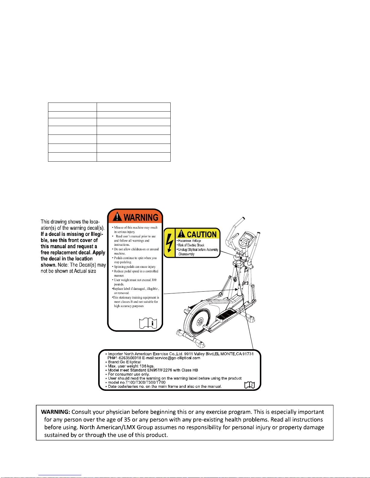
WARNING DECAL PLACEMENT

- 43 -
IMPORTANT SAFETY INSTRUCTIONS
WARNING: In order to reduce the risk of injury to any and all persons, READ and UNDERSTAND the following important
PRECATIONS and information before operating or allowing others to operate the elliptical exerciser
The owner has the responsibility of ensuring that all users of the elliptical exerciser are adequately informed of all warnings
and precautions
This elliptical exerciser should not be used by, on, or near children, invalids, or disabled persons.
This elliptical exerciser must only be used as described in the manual. Attachments that are not recommended by the
manufacturer must not be used.
Never operate the elliptical exerciser with the air openings blocked, Keep the air openings free of lint, hair and the like.
Never operate the elliptical exerciser on a soft surface such as a bed or a couch where the air openings may be blocked. And
never drop or insert any object into any opening.
Place the elliptical exerciser on a level surface. To protect the floor and carpet from damage, place a mat under the elliptical
exerciser.
DO NOT uses or store the elliptical exerciser outdoors, in a garage or covered patio, keep the elliptical exerciser away from
moisture and dust. The elliptical exerciser should be used indoors. Heat, moisture and dirt can adversely affect the operation of this
elliptical exerciser.
DO NOT operate the elliptical exerciser where aerosol products are being used or where medical oxygen is being
administered. Injuries to health may result from incorrect or excessive training. Instructions shall be giver in respect of every
major exercise type for which the equipment is designed.
The recommended minimum free space for access around the elliptical exerciser is 0.6m at each side and 0.3m at the rear of
the elliptical exerciser. This is to allow for an emergency dismount and passage around the elliptical exerciser.
Keep children under the age of 12 and pets away from the elliptical exerciser at all times.
No person weighing over 136 KGS 300 LBS) should use this elliptical exerciser.
NEVER allow more than one person on the elliptical exerciser at a time
Wear appropriate clothing when using the elliptical exerciser. DO not wear loose clothing that could become caught in the
elliptical exerciser. Appropriate athletic support clothing is recommended for both men and women. Always wear athletic shoes
intended for walking with a non-slip sole. NEVER use the elliptical exerciser with bare feet, while wearing stockings only or in
sandals.
The pulse monitor is not a medical device. Various factors, including the user’s movement, may affect the accuracy of pulse
rate readings. The pulse monitor is intended only as an aid to exercise in determining heart rate trends in general.
“WARNING! Heart rate monitoring systems may be inaccurate. Over exercising may result in serious injury or death.
If you feel faint stop exercising immediately”.
Do not attempt to raise lower or move the elliptical exerciser until it is properly assembled, ( See ASSEMBLY
INSTRUCTIONS.) You must be able to safely lift 100 pounds ( 46 KGS) in order to raise, lower or move the unit.
Do not place object under the elliptical exerciser in an attempt to change the incline of the elliptical exerciser.
Inspect and tighten all parts of the elliptical exerciser every three months.
This elliptical is design “ for Consummer Use Only “, not for any commercial or institutional, rental use.
Consult your physician before beginning your exercise program, incorrect of excessive training may cause the health injuries.
Tool require to assemble for the unit please refer to the end of parts list.
VST (variable stride length adjustment) refer to the page of how to operate the adjustor page 4 and 5
Any of the adjustment devices that could interfere with the user's movement should not be left projecting.
The equipment need tool to assembly , required tool Refer to the parts list with manual.
The product is a dependent only for indoor use specified with Class HB standard. With braking system—Speed independent.
The elliptical exerciser contents. Fit with. Lower body, upper and combined total body.
1:
Warning :

- 44 -
The equipment can be maintained only if it is examined regularly for damage and wear, e.g. ropes , and /or pulleys,
connection points ETC.
Warning:
an advice to replace defective components imm. and/or keep the equipment out of use till repair also special attention to
components most susceptible to wear out.
2.
The total Mass and surface area please refer to the following drawing:
3.
For using each of the stationary training equipment must accompanied by the user's manual. also with following important
info:
Manufacturer Full address: LMX International Inc.,
11Floor No. 93 Nanking East Road Taipei Taiwan, www.go-elliptical.com
To use the machine must notice the min. area required with space not less than 0.6M greater than the training area in
the directions from which the equipment is accessed. the free area must also include the area emergency dismount. where
the equipment is positioned adjacent to each other the value of free area may be shared. The free area and training area
shall be illustrated with a dedicated figure.
Warning :
If any of the adjustment devices are left projecting , they could interfere with user's movement.
Warning:
The free standing equipment shall be installed on a stable and leveled base
Warning:
Maximum User body for this equipment is 300LB/ (136KGS)
Frame area: 240cm*77cm (1.96 square meter)
Weight of the unit is 120 KGS

- 45 -
4.
Warning:
Equipment manufacturing date Code placed at the rear frame of the equipment with a Label
Year month serial#
5.
Warning:
The equipment is not with a free wheel system machine the equipment therefore the moving parts can not stopped imm.
6.
Warning:
The equipment is with Class B , is not suitable for high accuracy purposes .
SAVE THESE INSTRUCTIONS
**
17 10 010001

- 46 -
Personal MP3 and IPOD facility can work with the equipment's console to get the Sound out with the installed high/ low
speakers but to operate the degree of sound will be handled with your personal MP3 or IPOD equipment console not
provide the facility to operate your personal equipment.
**
With braking system—Speed independent.
**
When The Equipment with a cooling Fan facility, the Fan will operate with the Fan key as the following drawing shown:
with three Fan speed available--Low/ Mid / High.
Fan key
LX-03
**
Toggle switched enable user to easy to adjust the Stride /step length also the Work tension level the left hand switch with
the keys /
--means to increase the stride/step length
---means to decrease the stride/step length
the right hand switch with and
-- means up/increase the work tension level
-- means down / decrease the work tension level.
With the Toggle switches user will be easy to adjust the functions with left/right hand switched to avoid hands off the
handlebars and adjust the function data by touching with the penal on the console and stop the exercise program.

- 47 -
For Customer Service
1-267-808-3999
Email: cs@go-elliptical.com
 Loading...