

GOEBEL GO-39 Instruction Manual
14
1)
2)
3)
4)
Position Rack Bearing Plate (9) through the rear of Aluminum Body (1) into the slot, then push Gear Rack (8)
forward into the front of Aluminum Body (1).
Position the first tooth of Gear Sector (10) engaged with the first tooth of Gear Rack (8) <NOTE: Can use a
screwdriver to adjust Gear Sector (10) position.>, the hole of Gear Sector (10) should align with the front Pivot
Pin hole, install the first Pivot Pin (17) with Pivot Pin Washer (16) and Snap Ring (15) to the front Pivot Pin hole
of Aluminum Body (1). When assembled correctly, the wider section (W) of Gear Sector (10) should face down to
Lower Handle (12) position.
Swing Upper Handle (11) to the front and to position the first tooth of Driving Gear (11) engaged with the first
tooth of Gear Sector (10) <NOTE: Can use a screwdriver to adjust Gear Sector (10) position.>, the hole of
Driving Gear (11) should align with the rear Pivot Pin hole, install the second Pivot Pin (17) with Pivot Pin
Washer (16) and Snap Ring (15) to the rear Pivot Pin hole of Aluminum Body (1).
Reassemble Head (3) back to Aluminum Body (1) firmly.
B
REASSEMBLY:
NOTE: ALWAYS CHECK Fig. E CAREFULLY TO REASSEMBLE.
E.
1)
2)
PROBLEM - Rivet Mandrel can not be inserted into Working Nosepiece (2) or Spent Mandrel can not be ejected
after setting.
CAUSE 1 - Handles (11, 12) are not fully opened.
CORRECTION 1 - Open Handles (11, 12) fully.
CAUSE 2 - Working Nosepiece (2) is loose.
CORRECTION 2 - Tighten Working Nosepiece (2) with service Wrench (18).
PROBLEM - Rivet Mandrel is not gripped or Tool requires more operations than normal to set Rivet.
CAUSE 1 - Jaws (5) are dirty, worn or broken.
CORRECTION 1 - Clean or replace Jaws (5).
CAUSE 2 - Working Nosepiece (2) is loose.
CORRECTION 2 - Tighten Working Nosepiece (2) with service Wrench (18).
F. TROUBLE SHOOTING GUIDE:
When operating, ALWAYS WEAR SAFFTY
GOGGLES TO PROTECT YOUR EYES.
Tool must clear off and eject the Spent
Mandrel from Tool before setting next Rivet.
2017 GOEBEL
C
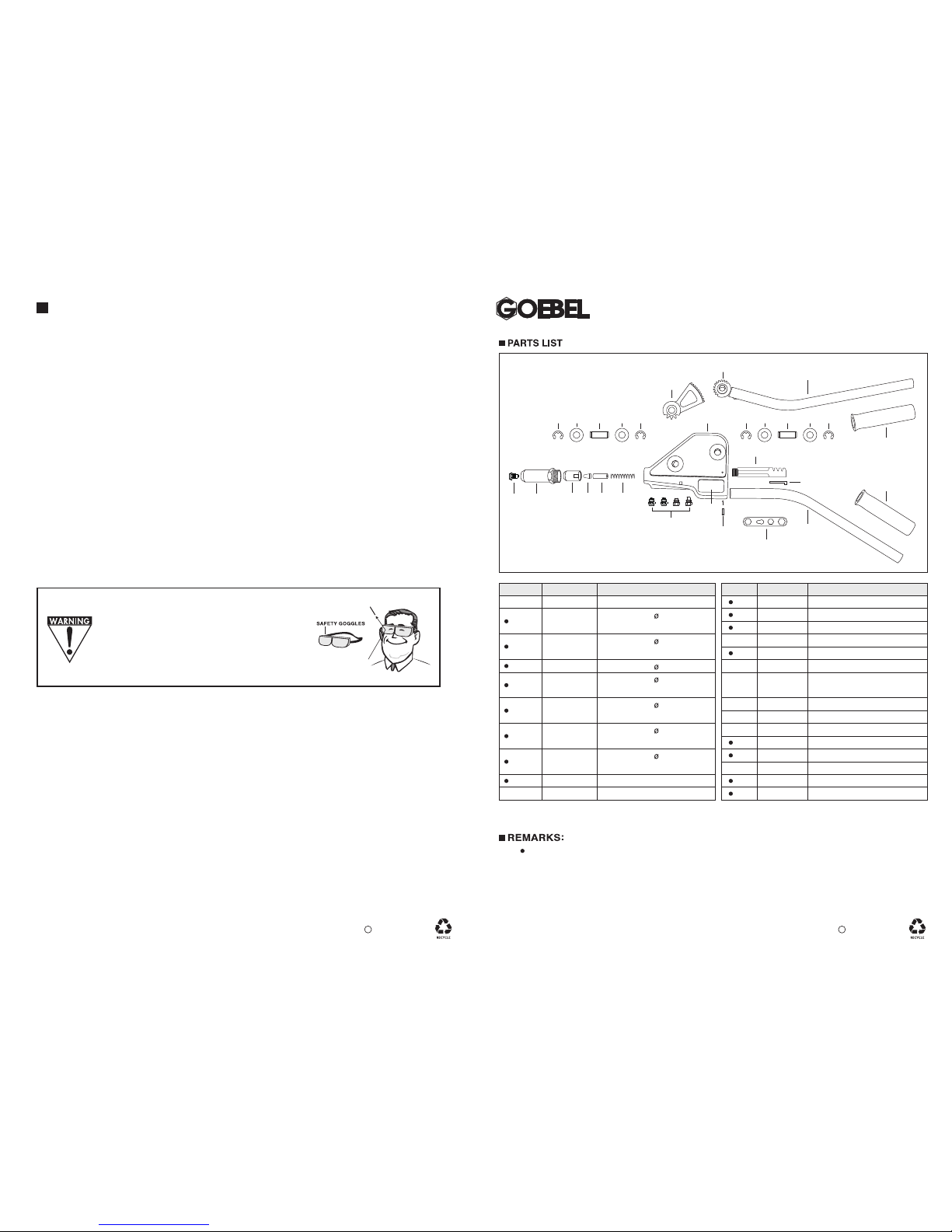
No. Part No. Part Name
1
2-40
2-48
2-64
2-48M
2-64M
2-64T
GO-39-0240
GO-39-0248
GO-39-0264
GO-39-01 Aluminum Body
Nosepiece, for 4.0 mm or
5/32” Rivet
Nosepiece, for 4.8/5.0 mm or
3/16” Rivet
Nosepiece, for 6.0 mm
Nosepiece, for 6.4 mm or
1/4” Rivet
Nosepiece, for 4.8/5.0 mm or
3/16” *Monobolt Rivet
Nosepiece, for 6.4 mm or
1/4” *Monobolt Rivet
Nosepiece, for 6.4 mm or
1/4” *T Rivet
Head, Standard
Jaw Case
No. Part No. Part Name
5
6
7
8
9
10
12
13
14
15
16
17
18
19
11 GO-39-11
GO-39-05
GO-39-06
GO-39-07
GO-39-08
GO-39-09
GO-39-10
GO-39-12
GO-39-13
GO-39-14
GO-39-15
GO-39-16
GO-39-17
GO-39-18
GO-39-19
1
4 5 6 7
18
14
19
19
13
8
15 16 17 16 1515 16 17 16 15
32
10
11
Driving Gear
12
2
9
2017 GOEBEL
C
Jaws, 3-pc Type
Jaw Pusher
Jaw Pusher Spring
Gear Rack
Rack Bearing Plate
Gear Sector
Driving Gear & Upper
Handle Assembly
Lower Handle
Name Plate
Drive Pin
Snap Ring
Pivot Pin Washer
Pivot Pin
Wrench
Grip
1) means Wearing Parts or Possible Missing Parts.
2) GO-39 Rivet Tool can set Ø4.8 mm (3/16") & Ø6.4 mm (1/4") *Monobolt Rivets and Ø6.4 mm (1/4") *T Rivet.
3) GO-39 Rivet Tool may install various Nosepieces for different applications on request.
4) GO-39 Rivet Tool can be packed in a Plastic Carry Case or Steel Carry Case on request.
5) *Monobolt Rivet and *T Rivet are the registered trademark of Avdel.
Gear Type Hand Rivet Tool GO-39
Industrial
Heavy Duty
GO-39-0260
GO-39-03
GO-39-04
GO-39-0248M
GO-39-0264M
GO-39-0264T
2-60
3
4
Lorem ipsum
A. FEATURES:
GOEBEL Big Shark GO-39 Heavy-Duty Rivet Tool has advanced Gear & Lever Dual System offering powerful
riveting capacity, 3-Jaw System provides not only stronger riveting power but also Rivet Mandrel easy loading and
Spent Mandrel easy ejection. Powerful riveting capacity can set 4.0, 4.8/5.0, 6.0, 6.4 mm or 5/32", 3/16", 1/4"
diameter Blind Rivets in all materials (Aluminum, Steel, Copper, Stainless Steel/Inox), also can set 4.8/5.0 & 6.4 mm
or 3/16" & 1/4" diameter *Monobolt rivets and set 6.4 mm or 1/4" diameter *T-Rivet. Quick-Maintain Head is easy to
clean or replace Jaws, Jaw Pusher and Jaw Pusher Spring. No adjustment is required after reassembling the parts.
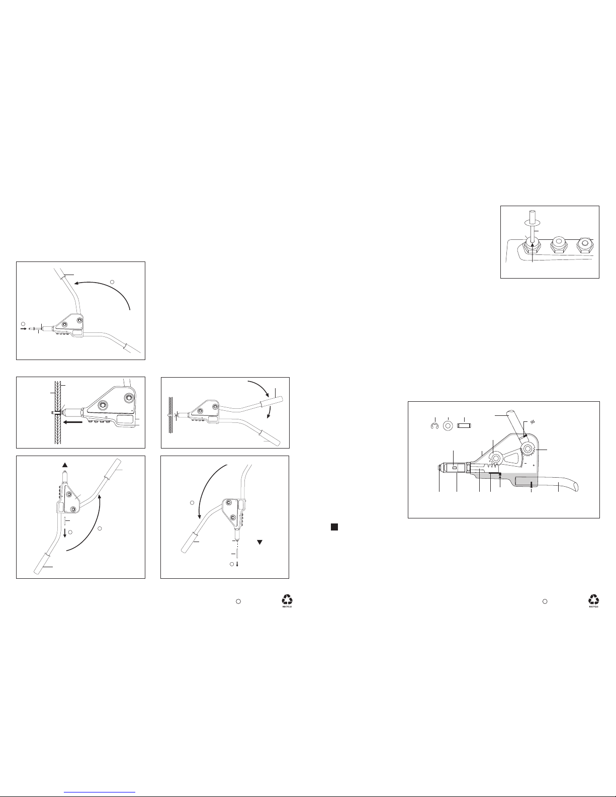
C. HOW TO SELECT AND CHANGE NOSEPIECES (2):
B. HOW TO OPERATE GO-39 TOOL TO SET BLIND RIVET:
1)
2)
3)
4)
Open Upper Handle (11) fully and insert Rivet Mandrel all
the way into Working Nosepiece (2) (Fig. 1).
Hold Rivet Mandrel in the Tool, insert Rivet Body into the
prepared hole of work pieces to be fastened, and press
Blind Rivet firmly to assure the Rivet Head is in contact
with the work piece (Fig. 2).
Squeeze Upper Handle (11) toward Lower Handle (12)
until Rivet Mandrel breaks off (Fig. 3). If more than one
squeeze is required to break off Rivet Mandrel, open
Upper Handle (11) fully, push Working Nosepiece (2) to
contact Rivet Head and squeeze Upper Handle (11)
again.
Open Upper Handle (11) fully and tilt Tool up to eject
the Spent Mandrel from the rear of Aluminum Body (1)
(Fig. 4), or open Upper Handle (11) fully and tilt Tool down
to eject the Spent Mandrel from the Working Nosepiece
(2) (Fig. 5).
2
1)
2)
3)
4)
Use the Mandrel of Blind Rivet to be applied as a Gauge, select the
Working Nosepiece (2) with the smallest hole that Mandrel can insert
into easily (Fig. C).
Close Tool Handles (11, 12) completely. CAUTION: If Tool Handles
(11, 12) are not completely closed before loosening the Working
Nosepiece (2) installed in Head (3), the Working Nosepiece (2) may
be forcibly ejected by the Jaw Pusher Spring (7). Do Not point Tool
at anyone when changing Nosepieces!
Remove Working Nosepiece (2) from Head (3) and store it into
Aluminum Body (1) with service Wrench (18).
Install and tighten the selected Working Nosepiece (2) to Head (3)
with service Wrench (18).
D. HOW TO CLEAN AND REPLACE JAWS (5), JAW PUSHER (6) AND JAW
PUSHER SPRING (7):
1)
2)
3)
4)
NOTE: If Jaws (5) can not bite or slip on the Rivet Mandrel, it is suggested to clean teeth of Jaws or replace new
Jaws (5). When Tool Handles (11, 12) are fully opened, but Jaws (5) are still not open completely, it is suggested
to check and replace new Jaw Pusher (6), Jaw Pusher Spring (7) and Nosepiece (2).
Close Tool Handles (11, 12) completely.
Remove Head (3) from Aluminum Body (1).
Remove Jaw Case (4), take out Jaws (5), Jaw Pusher (6) and Jaw Pusher Spring (7) from Jaw Case (4) and
Gear Rack (8). Clean teeth of Jaws with a wire brush, inspect Jaws for worn or broken teeth. Replace new
Jaws (5), Jaw Pusher (6) and Jaw Pusher Spring (7) if needed.
Lubricate outside surface of Jaws (5) and inside surface of Jaw Case (4) with a film of light machine oil.
Reverse above steps to reassemble, making sure Jaw Case (4) and Head (3) are tightened firmly.
3
E.E.HOW TO REPLACE GEAR RACK (8), RACK BEARING PLATE (9), GEAR SECTOR (10),
AND DRIVING GEAR & UPPER HANDLE ASSEMBLY (11):
NOTE:
Carefully check the Fig. E
and follow instructions,
otherwise damage might be
caused to the Tool.
1)
2)
3)
4)
Remove Head (3).
Remove Jaw Case (4), take out Jaws (5), Jaw Pusher (6) and Jaw Pusher Spring (7).
Remove the rear Snap Ring (15) and rear Pivot Pin Washer (16) from one side of Aluminum Body (1), then
press out rear Pivot Pin (17). Now the Driving Gear & Upper Handle Assembly (11) can be removed.
Remove front Snap Ring (15) and front Pivot Pin Washer (16) from one side of Aluminum Body (1), then press
out front Pivot Pin (17). Now the Gear Sector (10), Gear Rack (8) and Rack Bearing Plate (9) can be removed
from the rear of Aluminum Body (1). Replace the worn or broken Part(s).
A
DISASSEMBLY:
Fig. E
2017 GOEBEL
C
2017 GOEBEL
C
Fig. 1
Fig. 4
1
11
1
12
Spent
Mandrel
2
TOOL UP
Fig. 5
1
2
11
Spent
Mandrel
TOOL
DOWN
2
11
12
Fig. 3
2
Rivet Mandrel
Fig. 2
3.2
W
832
4
10
1
11
9
12
SLOT
14
Driving Gear
or 1/8”
Rivet
Fixed by a
15 16 17
Fig. C
Mandrel ( =Gauge)
Smallest Hole
2
2
11
Rivet Mandrel
2
1
Work Piece 1
Rivet Head
Work Piece 2
 Loading...