

Page 1
OPERATOR HANDBOOK
Heidra Pumps
HS80
HS100
HS100NC
HS100-SG
HS103
HS150
HS150NC
HS150-SG
HS150V
HS150V-SG
HS150HH
HS200
HS200-SG
HS250
HS300
READ BEFORE INSTALLING OR OPERATING THIS EQUIPMENT
Xylem Dewatering Solutions UK
Ltd
Quenington
Cirencester
Gloucestershire
GL7 5BX,
England
Tel: *44 (0)1285 750271
Fax: *44 (0)1285 750352
E-mail: sales@godwinpumps.co.uk
Website: www.godwinpumps.co.uk
Pump Serial Number
Xylem Dewatering Solutions
One Floodgate Road
Bridgeport
New Jersey 08014
U.S.A.
Tel: 856 467 3636
Fax: 856 467 4841
E-mail: sales@godwinpumps.com
Website: www.godwinpumps.com
Book No
95-0014-0000/A
Issue
6
Date
September 2012
Page 2

OPERATOR Book No.: 95-0014-0000/A
HANDBOOK Issue: 06
Page 2 of 30
CONTENTS
1 INTRODUCTION ........................................................................................................... 3
2 HOW TO USE THIS HANDBOOK ................................................................................. 3
3 SAFETY PRECAUTIONS .............................................................................................. 4
4 IDENTIFICATION .......................................................................................................... 4
5 INSTALLATION ............................................................................................................. 5
5.1 General Notes ....................................................................................................................................................... 5
5.2 Hydraulic motor ..................................................................................................................................................... 5
5.2.1 Determining motor inlet and outlet ports ....................................................................................................... 5
5.2.2 Front seal removal ........................................................................................................................................ 6
5.3 Hoses .................................................................................................................................................................... 7
6 OPERATION .................................................................................................................. 7
6.1 Starting ................................................................................................................................................................. 7
6.2 Draining ................................................................................................................................................................ 7
6.3 Storage Procedure ................................................................................................................................................ 7
7 MAINTENANCE ............................................................................................................ 8
7.1 HS80 pumps ......................................................................................................................................................... 8
7.1.1 Dismantling ................................................................................................................................................... 8
7.1.2 Reassembly .................................................................................................................................................. 9
7.2 HS100, HS100-SG, HS103, HS150, HS150-SG, HS150V & HS150V-SG pumps ............................................. 10
7.2.1 Dismantling ................................................................................................................................................. 10
7.2.2 Reassembly ................................................................................................................................................ 12
7.3 HS150HH, HS200-SG, HS200 & HS250 pumps................................................................................................. 13
7.3.1 Dismantling ................................................................................................................................................. 13
7.3.2 Reassembly ................................................................................................................................................ 14
7.4 HS300 pumps ..................................................................................................................................................... 16
7.4.1 Dismantling ................................................................................................................................................. 16
7.4.2 Reassembly ................................................................................................................................................ 18
7.5 HS100NC & HS150NC Pumps ........................................................................................................................... 19
7.5.1 Dismantling ................................................................................................................................................. 19
7.5.2 Reassembly ................................................................................................................................................ 21
7.5.2.1 Guide Pin Fitting ..................................................................................................................................... 21
7.5.2.2 Impeller Fit t ing ........................................................................................................................................ 23
7.5.2.3 Adjusting Impeller Front Clearance ......................................................................................................... 24
8 WARRANTY ................................................................................................................ 25
9 FAULT FINDING ......................................................................................................... 25
10 TECHNICAL DATA ..................................................................................................... 26
10.1 HS80, HS100, HS100-SG, HS103, HS150, HS150V & HS150V-SG Pumps ..................................................... 26
10.2 HS150HH, HS200, HS200-SG, HS250 & HS300 Pumps ................................................................................... 27
10.3 HS100NC & HS150NC Pumps ........................................................................................................................... 28
10.4 Fastener Torques ................................................................................................................................................ 29
Page 3
Book No.: 95-0014-0000/A OPERATOR
Issue: 06 HANDBOOK
Page 3 of 30
1 INTRODUCTION
The purpose of this Installation, Operating and Maintenance Handbook is to provide the owner or user of the equipment
with sufficient information to carry out those tasks on the Heidra hydraulically driven range of vertical suct io n
Submersible Pumps.
Pump models covered: HS80 HS103 HS150V-SG HS250
HS100 HS150 HS150HH HS300
HS100NC HS150NC HS200
HS100-SG HS150V HS200-SG
Because this handbook covers so many variants the user must ensure that they are reading the correct diagrams and
instructions for the unit they are working on.
Installation and maintenance is designed to be carried out using simple hand and service tools. A range of special tools
designed to ease dismantling and reassembly is available from Xylem Dewatering Solutions. When the user has
insufficient tools, experience or ability, this work should not be attempted. Under no circum stances should makeshift
tools or equipment be used, as this may adversely affect safe working practices and pump operation.
Ensure that suitably qualified personnel carry out the installation. The variety of conditions and environments in which
this equipment can be used means that the operator and those responsible must satisfy themselves as to the safety
and acceptability of each application and operating condition of this equipment. Under no circumstances will Xylem
Dewatering Solutions be responsible or liable for indirect or consequential damages arising from the use or application
of this equipment.
The pump may be supplied with or without a hydraulic motor fitted. This handbook covers the pump end only. For
packaged pump sets, information on equipment other than the pump end is contained in separate documentation.
Parts that have not been approved by Xylem Dewatering Solutions cannot be relied upon for correct material,
dimensions or finish. Xylem Dewatering Solutions cannot therefore be held responsible for any damage arising from the
use of such parts. This and failure to observe any instruction or procedure in this handbook will invalidate the warranty.
The information contained in this handbook was correct at the time of publication. It is subject to amendment at any
time. Should any doubt exist about the veracity of the information, contact Xylem Dewatering Solutions for clarification
before proceeding.
Associated Publications: - 95-0014-0000/B Operator handbook – Heidra Power Packs.
2 HOW TO USE THIS HANDBOOK
Read this section before installing, opera ting or carrying out any maintenance on the unit.
When the pump is being installed operated or maintained there are a number of practices that may lead to personal
injury or product damage. Your attention is drawn to the following symbols used throughout this handbook.
CAUTION. This caution symbol draws attention to special instructions or procedures which, if not correctly
followed, may result in damage to, or destruction of equipment.
WARNING. This warning symbol draws attention to special instructions or procedures which, if not strictly
observed, may result in personal injury.
WARNING. A WARNING SYMBOL WITH THIS TYPE OF TEXT DRAWS ATTENTION TO SPECIAL
INSTRUCTIONS OR PROCEDURES WHICH, IF NOT STRICTLY OBSERVED MAY RESULT IN SEVERE
PERSONAL INJURY, OR LOSS OF LIFE.
NOTE: A note is used to draw your attention to additional important information.
Page 4
OPERATOR Book No.: 95-0014-0000/A
HANDBOOK Issue: 06
Page 4 of 30
3 SAFETY PRECAUTIONS
WARNING. ALL ITEMS IN THIS SECTION, IF NOT STRICTLY OBSERVED, COULD RESULT IN SEVERE
PERSONAL INJURY OR LOSS OF LIFE.
Only use lifting equipment of suitable capacity for the size and weight of the equipment being lifted. The pump units are
designed for lifting by wire rope in use or slings around the workshop.
The equipment must always be lifted using safe working practices and in accordance with any local and national
guidelines or statutes. If in doubt, consult Xy lem Dew ater in g Soluti ons or a local lifting expert.
Whilst lifting the unit keep personnel well away and never allow people underneath.
Personnel working on the pump must always wear clean, correctly fitting clothing and safety footwear. Clothing
impregnated with oil or fuel can constitute a health hazard through prolonged contact with the skin and may also
constitute a fire hazard.
Check the type of liquid the pump has been used for before working on them. Residues could be hazardous to your
health. If in doubt, flush thoroughly with clean water before commencing work.
Rotating equipment presents a hazard in itself. Alert surrounding personnel before starting and post notifications whilst
in operation.
Moving parts are guarded to protect you. Guards removed for maintenance must be replaced before starting the pump.
Never insert anything into the pump body whilst the pump is running and the delivery hoses are disconnected.
Where connections are flanged, use all flange bolt holes and ensure the correct bolt size and quality is utilised when
connecting suction and delivery hoses.
Where connections are threaded, ensure the threads are sound before use and protected from damage if left
unconnected during storage or transpor ta tio n.
Although the pump can handle solids up to the size indicated in the Technical Data section of this manual, larger or
irregular solids may cause blockage with consequent damage to pump components.
Always allow adequate ventilation for the pump driver. Diesel engines require air for both combustion and cooling.
Electric motors require air for cooling purposes. This air must never be allowed to recirculate.
Be aware of burn and fire risks from items such as diesel engine exhaust pipes and silencers. Never place flammable
items around the unit.
Diesel engines exhaust and some of its constituents are known in the State of California to cause cancer, birth defects
and other reproductive harm.
Liquid pressure may still be present even after shutdown of the pump. Particular attention should be paid to delivery
lines that are long, or rise through any height, as these can contain large volumes of liquid. These lines must be
isolated and drained down before commencing work. Sudden release of this liquid can cause serious injury to an
operator either directly or indirectly through the rotational motion it can induce.
Never run the pump above its maximum speed.
Wear protective gloves when handling the equipment. There may be sharp metal edges.
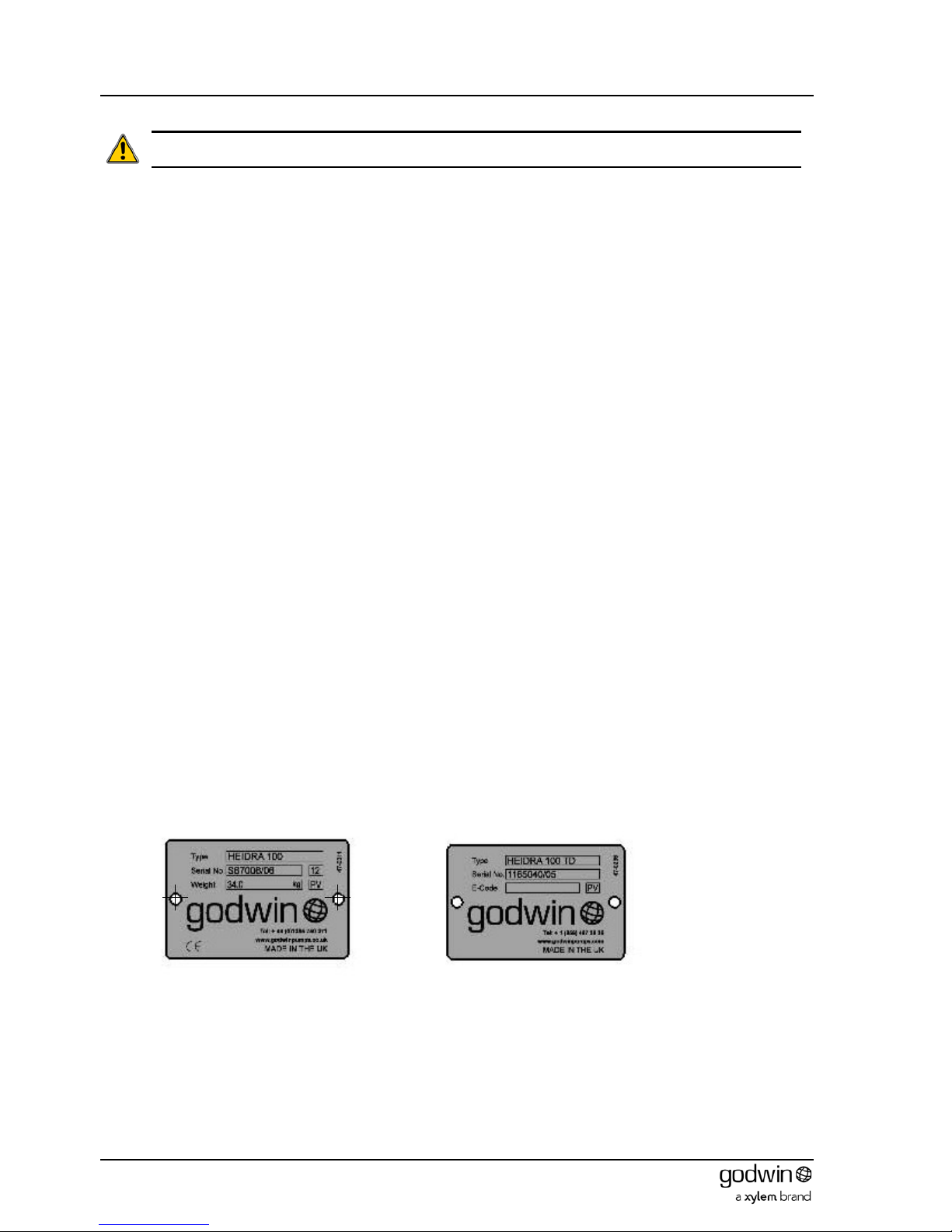
4 IDENTIFICATION
Every pump unit has a nameplate similar to one of those shown below. This nameplate lists the serial number and type
of the pump. These numbers must be quoted in any enquiry for spares or service.
Page 5
Book No.: 95-0014-0000/A OPERATOR
Issue: 06 HANDBOOK
Page 5 of 30
5 INSTALLATION
5.1 General Notes
Xylem Dewatering Solutions may refute warranty liability if the installation does not meet the requirements of the pump.
Consult Xylem Dewatering Solutions should any doubt exist over the suitability of an installation .
Only suitably qualified personnel (both mechanical and electrical) should carry out the installation. All local and national
regulations in force must be observed.
The delivery pipe work s houl d be kept as short as possible with a minimum number of large radii bends to minimise
pipe friction losses. Fitting larger diamet er pipe work than the pump outlet will maximise flow rates. Size increases in
the horizontal plane should be achieved using eccentric reducers to minimise the risks of air locks.
Lay out above ground piping runs before connecting to the pump to ensure that tight bends and other flow restrictions
are not included.
5.2 Hydraulic motor
CAUTION. Hydraulic motors on submersible pumps can suffer serious damage, including catastroph ic fail ure, if
they are operated in the wrong rotation.
This occurs when either the hydraulic pipe connections are made incorrectly; i.e. inlet line to the outlet side of the motor
and vice versa or, a wrong rotation motor is fitted on replacement. Failures result in unnecessary down time and
possible pollution from escaped hydraulic fluid. Correctly specifying a replacement motor and identifying the inlet and
outlet motor ports on new or existing motors before connection and start up is critical.
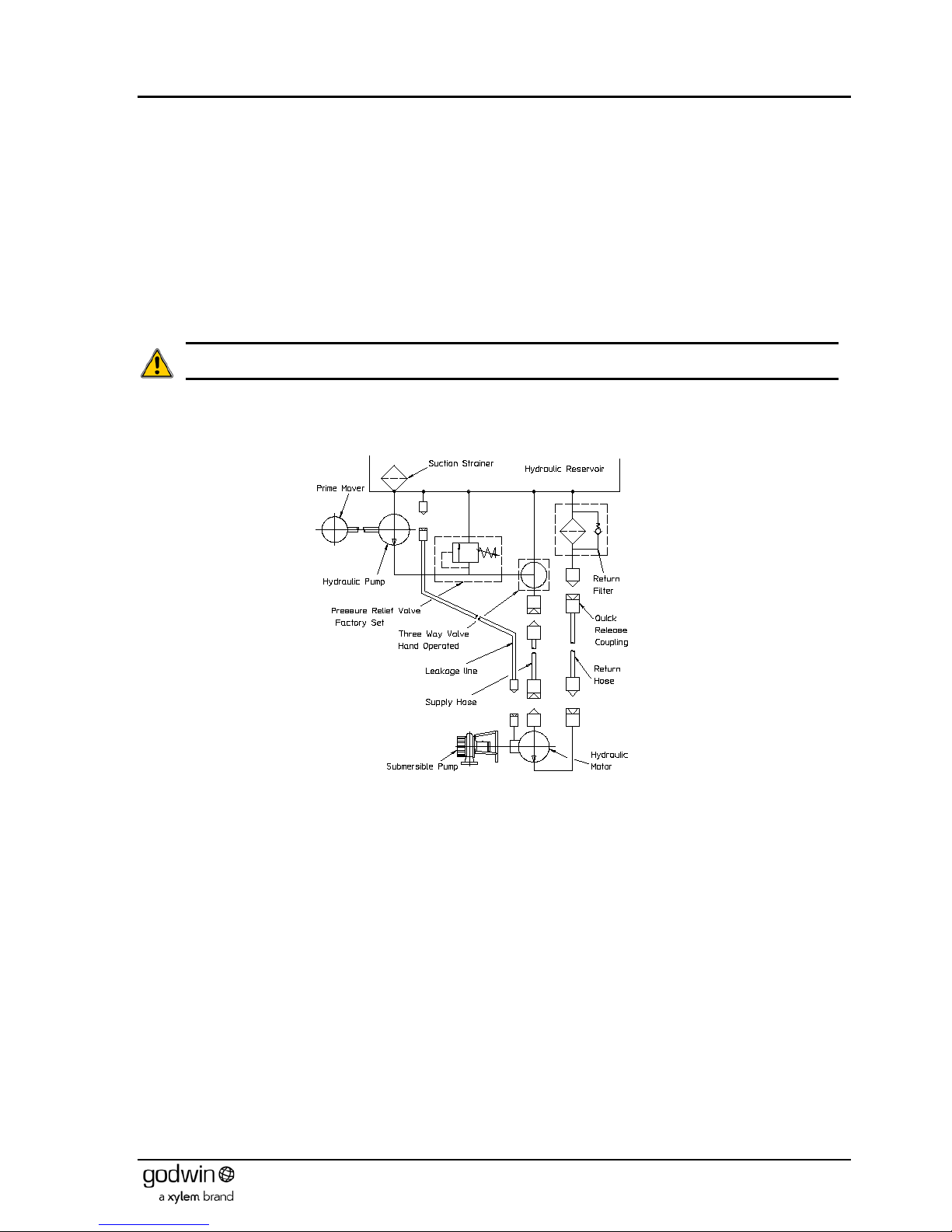
Figure 1 Hydraulic system schematic
A Xylem Dewatering Solutions supplied system is fitted with male and female quick release couplings at all terminal
points to prevent incorrect connection. A typical system illustrating this is shown in Figure 1.
5.2.1 Determining motor inlet and outlet ports
Many older motors have their bolted on connecting ports stamped with ‘IN’ or ‘HIGH PRESSURE’. These stampings
should be treated with a degree of caution as the ports could have previously been removed from the motor and
replaced incorrectly. Later motors will have their rotation and ‘IN’ stamped on the body (see Figure 3). These may be
taken as much more reliable, but even so caution must be exercised and the user must be satisfied that they are
correct before proceeding.
The Xylem Dewatering Solutions serial number of the pump is vitally important in any request for spares. It will be found
on a serial plate located on the main body of the pump. If the serial number cannot be found then the following
procedure should be employed to determine the requirement.
It is important to understand that when specifying any directional rotation it must be qualified by stating the direction in
which that rotation is viewed. This is illustrated in Figure 2 where, when viewed from above the submersible pump, the
direction of rotation is clockwise, but the Xylem Dewatering Solutions method of specification is the direction of rotation
looking from the underside (i.e. the inlet side) of the pump and is anti-clockwise. Figure 2 shows a Heidra 10022
submersible pump but the principles are equally applicable to any submersible pump.
1. Identify the submersib le pump rot ati on – clockwise or anti-clockwise? (Refer to Figure 2).
2. The hydraulic motor rotation notation is the same as the pump; i.e. an anti-clockwise pump requires an anticlockwise motor and vice versa.
Page 6

OPERATOR Book No.: 95-0014-0000/A
HANDBOOK Issue: 06
Page 6 of 30
3. The output shaft from the motor is offset one way from the port centres in the body (see Figure 3). Ensure the
motor is in the correct orientation to Figure 3 and identify the motor ports accordingly. Mark appropriately. Note
that the hydraulic fluid passes around the outside of the gear wheels and not through the middle.
4. Connect the high pressure feed to the ‘IN’ inlet port and the low pressure return to the outlet port.
Figure 2 Pump rotation
Figure 3 Hydraulic motor ports
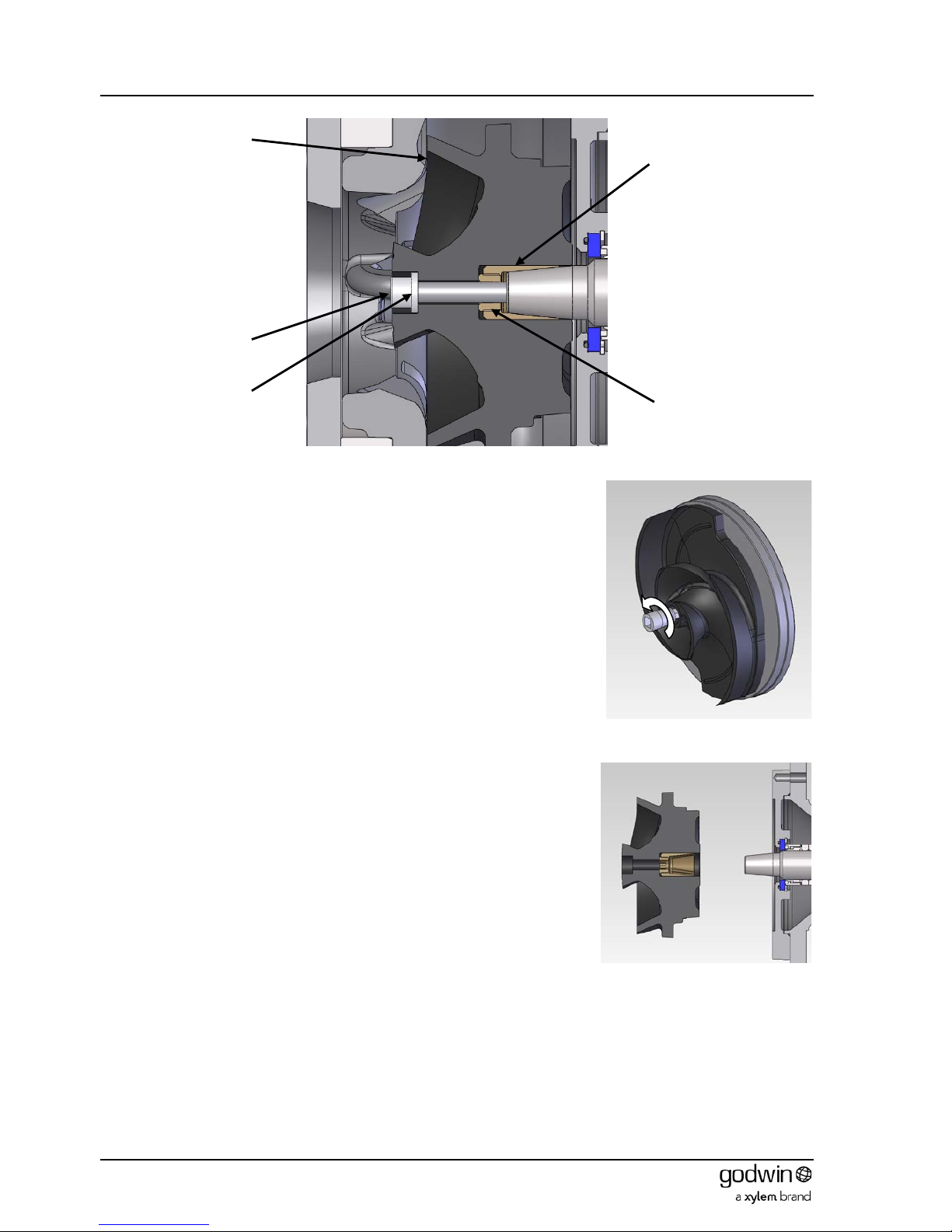
5.2.2 Front seal removal
The bearings (and mechanical seal for HS80 units) of HS80, HS100, HS150, HS100-SG,
HS150V, HS150V-SG, HS100NC and HS150NC pumps are designed to be lubricated
and cooled by the hydraulic motor system oil. The oil is bled from the motor by removing
the seal from the front cover. A typical motor front cover arrangement is shown in Figure
4. Removing the circlip allows the seal and O-ring to be withdrawn. On some pumps the
seal is fitted from the inside of the front cover. In these cases the front cover will need to
be removed prior to removing the seal.
Note that this oil is returned to the hydraulic reservoir by a separate leakage line (see
Figure 1).
On all other pumps the bearings and mechanical seal are enclosed in their own
separately sealed housings and the motor seal must not be removed.
Figure 4 Typical motor front seal
arrangement
Page 7

Book No.: 95-0014-0000/A OPERATOR
Issue: 06 HANDBOOK
Page 7 of 30
5.3 Hoses
Maximum recommended hose lengths are: -
Pump
Flow Rate
GPM(Imperial)/ litres per min
Hose length
Metres/feet
HS80
2.6 / 12
35 / 115
2.4 / 11
45 / 148
2.2 / 10
50 / 164
2.0 / 9.2
65 / 213
The lengths are for ½”nominal bore hose with SAE 10 oil at 15°C. They may be increased by 50% if
¾”nominal bore hoses are used.
HS100
9.6 / 36.4
15 / 49.2
9.0 / 34.0
20 / 65.5
8.5 / 32.0
30 / 98.5
8.1 / 29.5
35 / 115
6.8 / 25.5
40 / 131
The lengths are for 5/8”nominal bore hose with SAE 10 oil at 15°C. They may be increased by 50% if
¾”nominal bore hoses are used.
HS150
14.7 / 55.8
20 / 65.5
(3)
14.5 / 55.0
30 / 98.5
(3)
13.7 / 52.0
35 / 115
(3)
13.0 / 49.0
40 / 131
(3)
The lengths are for 3/4” nominal bore hose with SAE 10 oil at 15°C. They may be increased by 50% if 1”
nominal bore hoses are used.
Long hose lengths result in high back pressure in the return line
Table 1 Recommended hose length table
6 OPERATION
6.1 Starting
1. Before starting a system, the three-way valve (see Figure 1) is turned to direct the flow back into the reservoir.
2. Start the prime mover. This immediately starts the hydraulic pump. The flow should be allowed to continue back
into the reservoir for a few minutes to allow the system to warm and enables visual checking for leaks or faults.
3. Operate the three-way valve to direct the flow to the hydraulic motor and product pump.
4. Vary the speed of the prime mover to regulate the product pump.
CAUTION. The three way valve should never be used to control the speed of the hydraulic motor and product
pump. This will lead to overheating of the hydraulic fluid and consequential failure.
6.2 Draining
A pump situated in a position where it could be exposed to frost must be drained when that possibility exists unless
steps have been taken to alleviate the condition.
CAUTION. Failure to drain the pump and non-return valve in these conditions could result in the pumped
product residue freezing and cracking the casing.
It should also be drained if it is to be stopped for an extended period.
6.3 Storage Procedure
Disconnect the pump from the pipelines.
Allow air to circulate and try to ensure that the body is completely dry internally.
A proprietary flushing/protective fluid may be used if required. Ensure that this is compatible with any pump residue
before using it.
Place the pump to a cool dry storage area.
Page 8
OPERATOR Book No.: 95-0014-0000/A
HANDBOOK Issue: 06
Page 8 of 30
7 MAINTENANCE
In this section it is assumed that the pump: -
has been removed from its operating position
has been drained of pumped product
has been drained of hydraulic oil
all hoses have been disconnected
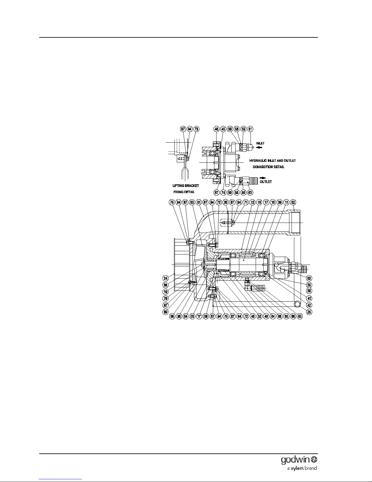
7.1 HS80 pumps
7.1.1 Dismantling
1. Undo set screws (75) holding lifting
bracket (25) to both the pump body (1)
and outlet pipe (2). Remove lifting
bracket.
2. Undo set screws (75) holding the strainer
(24) to the pump body (1). Remove
strainer.
3. Release the screws (72) holding the
bearing bracket, wear plate and impeller
assembly to the pump body (1). (NOTE.
These are the screws on the larger PCD.
The screws on the smaller PCD retain the
wear plate to the bearing bracket).
4. Extract the bearing bracket assembly
from the pump body (1). The extension
pipe (2) and front wear plate (6) can be
removed from the pump body (1) if
required by removing the respective
screws (71) or (79).
5. Place a bar through the vanes of the
impeller (3) to lock it in position and
prevent rotation. Unscrew (RH thread)
and remove the impeller retaining screw
(68) and washer (19). Note that the screw
has a nylon plug through it that provides a
self-locking function. The screw will
therefore remain stiff to turn until this
nylon plug is clear of the shaft.
6. Remove the impeller (3) and the wearing
sleeve (4). Remove the impeller shims (if
any were fitted) noting the number and
thickness for comparison on rebuild.
Remove the key (36).
7. Release the screws (72) holding the rear wear plate
(5) to the bearing bracket assembly. Remove the
wear plate to expose the mechanical seal housing (8).
8. Extract the mechanical seal housing (8) complete with O-ring (46) from the bearing bracket (12). The stationary
seat of the mechanical seal will probably stay in the seal housing and can be removed by pressing out.
9. Carefully extract the mechanical seal (52) from the bearing bracket.
10. Release the screws (74) holding the hydraulic motor (55) to the bearing cover (11) and remove the motor.
11. Undo the screws (67) and remove the bearing cover (11) from the bearing bracket.
12. Press the shaft assembly out of the bearing bracket from the pump end.
13. Flatten the tags on the locking washer (42), prevent the shaft from rotating, and unscrew the bearing locknut (41).
14. Pull the ball bearing (39) off the shaft and remove the bearing outer (17) and inner (16) spacers.
15. Pull the roller bearing inner race (40) off the shaft.
Dismantling is now complete. Inspect all parts for damage or wear.
Figure 5 Typical HS80 pump
Page 9
Book No.: 95-0014-0000/A OPERATOR
Issue: 06 HANDBOOK
Page 9 of 30
7.1.2 Reassembly
New seals and O-rings must be fitted when reassembling. It is also prudent to fit a new impeller retaining screw.
1. Heat both bearings (39 & 40) with a temperature controlled bearing heater until they are a consistent 110°C. Do
not overheat or allow the bearings to remain at this temperature for longer than their fitting time.
CAUTION. Bearing races must be pressed into position and not hammered either directly or by drift. Direct
hammering will damage the bearing or rollers. Drift hammering will introduce swarf into the assembly. Either will
result in early bearing failure.
2. Once up to temperature, slide the roller bearing inner race (40) up hard against the shaft shoulder, fit the bearing
inner (16) and outer (17) spacers and slide the ball bearing (39) up hard onto the spacers. Hold them in position for
a minimum of 30 seconds. The locknut (41) fitted without the tab washer is suitable for this purpose. This allows
the races to grip the shaft and prevent them from creeping away from the shoulder during cooling. Let the
assembly cool completely.
3. Once cool, remove the lock nut (41), fit the locking washer (42) and refit the lock nut. Knock up at least two tags on
the locking washer to secure.
4. Press the shaft assembly into the bearing bracket (12) from the motor end until the back of the ball bearing race is
6-7 mm below the surface. Use the bearing cover (11) without an O-ring (46) to press the assembly to its final
position.
5. Remove the bearing cover (11), fit an O–ring (46), refit the cover and secure with screws (67).
6. Fit the hydraulic motor (55) to the bearing cover (11) and secure with screws (74). Note that the oil seal in the front
of the motor must be removed beforehand (see section 5.2.2 for details).
CAUTION. Failure to remove the hydraulic motor oil seal will block the oil feed to both the bearings and
mechanical seal. Immediate failure of the seal and damage to the bearings will result.
7. Clean the shaft thoroughly and lubricate with clean water or a diluted soft soap solution. Do not use heavy grease,
silicone or PTFE based lubricants, as these would prevent the seal from gripping the shaft.
CAUTION. Mechanical Seals are precision engineered devices. Extreme care must be taken to ensure that no
damage occurs to the lapped faces. These faces must be kept absolutely clean throughout the entire
installation. Do not touch them or allow any contaminant to come into contact with them. Soiled faces will have
to be cleaned with appropriate degreasing cleaner and soft tissue. Failure to observe these precautions will
lead to premature seal failure.
8. Carefully slide the rotating parts of the mechanical seal (52) over the shaft until they abut the shaft shoulder.
9. Press the stationary seat of the mechanical seal (52) into the seal housing (8). Fit an O-ring (46) to the outside
diameter and carefully press the assembly into the bearing bracket from the pump end.
10. Fit the rear wear plate (5) to the bearing bracket assembly using screws (72).
11. Fit the key (36), wearing sleeve (4) and impeller (3) to the shaft. Secure with the impeller retaining screw (68) and
washer (19).
12. Measure the clearance between rear of impeller and rear wear plate. Remove the impeller and add shims as
necessary to obtain the clearance given in the Technical Data section.
13. Refit the impeller, lock the assembly with a bar through the vanes of the impeller and torque the retaining screw to
the value given in the Technical Data section.
14. Fit the front wear plate (6) to the pump body (1) using screws (79), spring (97) and plain (89) washers.
15. Fit the pump body (1) to the bearing bracket, wear plate and impeller assembly with screws (75), spring (94) and
plain (87) washers. Measure the clearance between the front of the impeller and front wear plate and check that it
corresponds to the value given in the Technical Data section. If it is not correct then the build is incorrect and the
cause must be investigated before proceedin g fur ther.
16. Place a gasket (30) on the pump body (1), fit the extension pipe (2) and attach with screws (71) and washers (87).
17. Attach the strainer (24) to the pump body with screws (75), spring (94) and plain (87) washers.
18. Attach the lifting bracket (25) to both the pump body (1) and outlet pipe (2) using set screws (75), spring (94) and
plain (87) washers.
Assembly is now complete, but before attaching the hydraulic lines, the unit must be filled with hydraulic oil to prevent
dry running on start up. Ensure the unit is completely filled with no air lock s before pr oc eed i ng.
Page 10

OPERATOR Book No.: 95-0014-0000/A
HANDBOOK Issue: 06
Page 10 of 30
7.2 HS100, HS100-SG, HS103 , HS150, HS150-SG, HS150V & HS150VSG pumps
NOTE! The HS100NC & HS150NC pumps differ only in volute, impeller and associated parts. Therefore these
dismantling and reassembly instructions can be followed in principle, but refer to section 7.5 for detail differences.
Note that dismantling and reassembly procedures refer to the item numbers in the illustrations and are correct for a
directly corresponding build. However because of the number of possible build configurations some interpretation of the
diagrams will be necessary for other pump variants. Some additional illustrations have been included to aid in this
purpose.
7.2.1 Dismantling
Horizontal and vertical discharges pumps are
available. Only one representative type of each
pump has been illustrated for clarity.
1. If not previously done remove the stud
adaptor (87) and associated fittings and
drain the bearing bracket of hydraulic oil.
2. Remove plug (83) and drain the seal housing
of oil.
3. HS100 pumps: -Undo set screws (56)
holding lifting bracket (17) to the pump body
(1).
HS150 pumps: - Undo nuts (64) from bolts
(55) holding lifting bracket (17) to the
extension pipe (6) and screws (59) holding
lifting bracket to the pump body (1).
Remove lifting bracket.
4. Undo set screws (HS100 – 57; HS150 – 60)
holding the strainer (16) to the pump body
(1). Remove strainer.
5. Release the screws (HS100 – 55; HS150 -
58) holding the bearing bracket, wear plate
and impeller assembly to the pump body
(1). (NOTE. These are the screws on the
larger PCD. The screws on the smaller
PCD retain the wear plate to the bearing
bracket).
6. Extract the bearing bracket assembly from the
pump body (1). The front wear plate (5) can be
removed from the pump body if required by
removing the screws (HS100 – 58; HS150 - 59).
7. Place a bar through the vanes of the impeller
(3) to lock it in position and prevent rotation.
Unscrew (RH thread) and remove the impeller
retaining nut (63) and washer (14). Note that
the nut has a nylon insert that prov ides a selflocking function. The nut will therefore remain
stiff to turn until this nylon insert is clear of the
shaft.
8. Pull the impeller (3) off the shaft (13) and
remove the key (9). Two off M10 tapped jacking
screw holes are provided in the boss of the
impeller if required to aid in its removal.
9. Release the screws (HS100 – 55; HS150 - 58)
holding the rear wear plate (4) to the bearing
bracket assembly. Remove the wear plate to
expose the mechanical seals (40 & 39). The
wear plate contains a seal seat (20) that is
removed by releasing the circlip (43).
10. Slide the mechanical seals (40 & 39) off the
shaft (13) and extract the seal seat from the
bearing bracket (10).
Figure 7 Typical HS100 pump
Figure 6 Typical 15022 pump
Page 11
Book No.: 95-0014-0000/A OPERATOR
Issue: 06 HANDBOOK
Page 11 of 30
11. Release the nuts (65) holding the hydraulic
motor (76) to the bearing cover (11) and
remove the motor.
12. HS100 only. Undo the screws (60) and
remove the bearing cover (11) from the
bearing bracket.
HS150 only. Remove bearing cover (11) from
bearing bracket.
13. Press the shaft assembly out of the bearing
bracket from the pump end.
14. Remove the internal plugs (84) from the pump
end of the bearing bracket and using a pair of
rods, press the roller bearing outer race out.
15. Flatten the tags on the locking washer (50),
prevent the shaft from rotating, and unscrew
the bearing locknut (49).
16. Pull the ball bearing (48) off the shaft and remove
the bearing outer and inner (12) spacers.
17. Pull the roller bearing inner race (47) off the
shaft.
Dismantling is now complete. Inspect all parts for
damage or wear.
Figure 8 Typical HS150V pump
Figure 9 Typical HS150V-SG
Page 12

OPERATOR Book No.: 95-0014-0000/A
HANDBOOK Issue: 06
Page 12 of 30
7.2.2 Reassembly
New seals and O-rings must be fitted when reassembling. It is also prudent to fit a new impeller retaining nut.
1. Heat both bearings (47 & 48) with a temperature controlled bearing heater until they are a consistent 110°C. Do
not overheat or allow the bearings to remain at this temperature for longer than their fitt ing t ime.
CAUTION. Bearing races must be pressed into position and not hammered either directly or by drift. Direct
hammering will damage the bearing or rollers. Drift hammering will introduce swarf into the assembly. Either
will result in early bearing failure
2. When to temperature, slide the roller bearing inner race (47) up hard against the shaft shoulder, fit the bearing
inner and outer (12) spacers and slide the ball bearing (48) up hard onto the spacers. Hold them in pos itio n for a
minimum of 30 seconds. Use the locknut (49) fitted without the tab washer for this purpose. This allows the races
to grip the shaft and prevent them from creeping away from the shoulder during cooling. Let the assembly cool
completely.
3. Once cool, remove the lock nut (49), fit the locking washer (50) and refit the lock nut. Knock up at least two tags on
the locking washer to secure.
4. Press the roller bearing inner race down to the bottom of the bearing bracket (10) bore. Fit plugs (84) to the internal
channels at the pump end of the bearing bracket.
5. Press the shaft assembly into the bearing bracket from the motor end until it is clamped hard together.
6. Fit an O–ring (36) to the bearing cover (11) and for 10022 pumps attach the cover to the bearing bracket with
screws (60). On HS150 pumps place the cover in position.
7. Fit the hydraulic motor (76) and O-ring (34) to the bearing cover (11) and secure with half nuts (65) for HS100
pumps or full nuts (65) for HS150 pumps and spring washers (68). Check t o see t hat the oil seal in the front of the
motor has been removed (see sect ion 5.2 details).
CAUTION. Failure to remove the hydraulic motor oil seal will block the oil feed to the bearings. Damage to the
bearings will result.
8. Clean the shaft thoroughly and lubricate with clean water or a diluted soft soap solution. Do not use heavy
grease, silicone or PTFE based lubricants, as these would prevent the seal from gripping the shaft.
CAUTION. Mechanical Seals are precision engineered devices. Extreme care must be taken to ensure that no
damage occurs to the lapped faces. These faces must be kept absolutely clean throughout the entire
installation. Do not touch them or allow any contaminant to come into contact with them. Soiled faces will have
to be cleaned with appropriate degreasing cleaner and soft tissue. Failure to observe these precautions will
lead to premature seal failure.
9. Carefully slide the rotating parts of the mechanical seals (39 & 40) over the shaft until they abut the seal seat.
10. Place an O-ring (35) in the groove in the back of the rear wear plate (4), place the seal seat (20) in position and
secure with circlip (43).
11. Fit the rear wear plate (4) to the bearing bracket assembly using screws (HS100 – 55; HS150 – 58) and spring
washers (68) having first fitted an O-ring (37) to the bearing bracket.
12. Fit the key (9) and impeller (3) to the shaft. Secure with the impeller retaining nut (63) and washer (14).
13. Measure the clearance between rear of impeller and rear wear plate. Remove the impeller and add shims (HS100
– 95; HS150 – 95, 96 & 97) as necessary to obtain the clearance given in the Technical Data section.
14. Refit the impeller, lock the assembly with a bar through the vanes of the impeller and torque the retaining screw to
the value given in the Technical Data section.
15. Fit the front wear plate (5) to the pump body (1) using screws (HS100 – 58; HS150 - 59) and spring washers
(HS100 – 69; HS150 - 68).
16. Fit the pump body (1) to the bearing bracket, wear plate and impeller assembly with screws (HS100 – 55; HS150 -
58) and spring washers (68). Measure the clearance between the front of the impeller and front wear plate.
Remove the pump body from the assembly, detach the wear plate from the pump body and fit shims (HS100 - 97,
98 & 99; HS150 - 94) to obtain the clearance given in the Technical Data section. Reassemble and recheck.
17. Attach the strainer (16) to the pump body with screws (HS100 - 57; HS150 - 60) and spri ng w ashers (68).
18. HS100 pumps: -Attach the lifting bracket (17) to the pump body using set screws (56) and spring washers (68).
HS150 pumps: - Attach the lifting bracket (17) to the pump body with screws (59), plain (71) and spring (68) and
with nuts (64), bolts (55) and washers (71) to the extension pipe (6).
19. Fill the seal chamber with oil (see Technical Data section) ensuring that no air pockets remain and plug off with
plug (83).
Assembly is now complete, but before attaching the hydraulic lines, the unit must be partially filled with hydraulic oil to
prevent dry running on start up.
Page 13

Book No.: 95-0014-0000/A OPERATOR
Issue: 06 HANDBOOK
Page 13 of 30
7.3 HS150HH, HS200-SG, HS200 & HS250 pumps
Note that dismantling and reassembly procedures refer to the item numbers in the illustration and are correct for a
directly corresponding build. However because of the number of possible build configurations some interpretation of the
diagram will be necessary for other pump variants. Some additional illustrations have been included to aid in this
purpose.
7.3.1 Dismantling
1. If not previously done remove the plugs (45)
from the bearing bracket (75) and drain the
oil. Remove the plug (44) from the adaptor (8)
and drain any leakage.
2. Remove the plug (45) from the adaptor and
drain the seal housing of oil.
3. Undo set screws (56) holding the strainer (9)
to the pump body (1). Remove strainer.
4. Release the nuts (70) holding the bearing
bracket, adaptor, wear plate and impeller
assembly to the pump body (1). (NOTE.
These are the nuts on the larger PCD. The
screws on the smaller PCD retain the wear
plate to the bearing bracket).
5. Extract the bearing bracket assembly from the
pump body (1). The front cover (2) and wear
plate (5) may be removed from the body by
releasing the nuts (70). The front wear plate
can be removed from the front cover by
removing the screws (57).
6. Place a bar through the vanes of the impeller
(3) to lock it in position and prevent rotation.
Unscrew (RH thread) and remove the impeller
retaining nut (47) and washer (48). Note that
the nut has a nylon insert that provides a selflocking function. The nut will therefore remain
stiff to turn until this nylon insert is clear of the
shaft.
7. Pull the impeller (3) off the shaft (80) and
remove the key (49). Four off M8 tapped
jacking screw holes are provided in the boss
of the impeller if required to aid in its removal.
Shims (15, 16, 17 & 18) may be found on the
shaft behind the impeller. These have been
used to achieve the required rear clearance.
Keep a check on quantity and thickness for
comparison purposes when rebuilding.
8. Release the nuts (10) holding the rear wear
plate (6) to the bearing bracket assembly.
Remove the wear plate.
9. Undo and remove the socket head cap
screws (60) holding the inner wear plate and
seal carrier (4) to the adaptor (8). Remove
this inner wear plate with care as it carries the
seal seat (27). Once removed, the seal seat
can be removed from the wear plate by
undoing the screws (59) to release the seal
clamping plate (7).
10. The mechanical seals (29) are now exposed
and can be released by undoing their
clamping screws. Ensure that the screws are
fully retracted before moving the seals to
ensure that they do not mark the shaft during
removal. Slide the mechanical seals (2 off 29)
off the shaft (80) and extract the seal seat from
the adaptor (8).
Figure 10 Typical HS200 pump
Page 14
OPERATOR Book No.: 95-0014-0000/A
HANDBOOK Issue: 06
Page 14 of 30
11. Release the nuts (69) from bolts (54) and remove the
lifting bracket (11) and adaptor (8) from the bearing
bracket assembly.
12. Release the screws (57) holding the hydraulic motor (84)
to the bearing cover (77) and remove the motor.
13. Undo the screws (61) and remove the bearing cover (77)
from the bearing bracket (75).
14. Press the shaft assembly out of the bearing bracket from
the pump end.
15. The pump end bearing cover (76) can be removed from
the bearing bracket (75) by releasing the bolts (55).
16. Press the roller bearing (89) outer race out of the bearing
bracket.
17. Flatten the tags on the locking washers (92), prevent the
shaft from rotating, and unscrew the bearing locknuts
(91).
18. Pull the angular contact ball bearings (2 off 90) off the
shaft and remove the bearing spacer (78).
19. Pull the roller bearing (89) inner race off the shaft.
Dismantling is now complete. Inspect all part s for damage or
wear.
7.3.2 Reassembly
New seals and O-rings must be fitted when reassembling. It is also prudent to fit a new impeller retaining nut.
1. Heat the roller bearing (89) inner race and both angular contact ball bearings (2 off 90) with a temperature
controlled bearing heater until they are a consistent 110°C. Do not overheat or allow the bearings to remain at this
temperature for longer than their fitting time.
CAUTION. Bearing races must be pressed into position and not hammered either directly or by drift. Direct
hammering will damage the bearing or rollers. Drift hammering will introduce swarf into the assembly. Either
will result in early bearing failure.
Figure 12 Typical HS150HH pump
Figure 11 Typical HS150-SV pump
Page 15

Book No.: 95-0014-0000/A OPERATOR
Issue: 06 HANDBOOK
Page 15 of 30
2. Once up to temperature, slide the roller bearing (89) inner race up hard against the shaft shoulder, fit the bearing
spacer (78) and slide the angular contact ball bearings (2 off 90) up hard onto the other shaft shoulder. Hold them
in position for a minimum of 30 seconds. The lock nuts (91) fitted without the tab washers are suitable for this
purpose. This allows the races to grip the shaft and prevent them from creeping away from the shoulder during
cooling. Let the assembly cool completely.
3. Once cool, remove the lock nuts (91), fit the locking washers (92) and refit the lock nuts. Knock up at least two tags
on the locking washers to secure.
4. Press the roller bearing (89) outer race sufficiently into the bearing bracket (75) bore so that it is deep enough to
allow the bearing covers (76) spigot to engage with the bore. Fit the bearing cover without a lip seal (95) or O-ring
(36) and press the outer race fully home.
5. Press the shaft assembly into the bearing bracket from the motor end until it is clamped hard together.
6. Remove the pump end bearing cover (76), fit a lip seal (95) and O-ring (36) and refit the cover.
7. Fit O–ring (36) to motor end bearing cover (77). Attach the cover to bearing bracket with screws (61).
8. Fit the hydraulic motor (84) and O-ring (37) to the bearing cover (77) and secure with screws (57) and spring
washers (64). Note that the hydraulic motor front oil seal is NOT removed for this pump model.
9. Attach the adaptor (8) to the bearing bracket assembly using screws (57) and spring washers (64).
10. Attach lifting frame (11) to bearing bracket assembly using bolts (54), spring washers (63) and nuts (69).
11. Clean the shaft thoroughly and lubricate with clean water or a diluted soft soap solution. Do not use heavy grease,
silicone or PTFE based lubricants, as these would prevent the seal from gripping the shaft.
CAUTION. Mechanical Seals are precision engineered devices. Extreme care must be taken to ensure that no
damage occurs to the lapped faces. These faces must be kept absolutely clean throughout the entire
installation. Do not touch them or allow any contaminant to come into contact with them. Soiled faces will have
to be cleaned with appropriate degreasing cleaner and soft tissue. Failure to observe these precautions will
lead to premature seal failure.
12. Press the seal seat into the adaptor (8).
13. Carefully slide the rotating parts of the first mechanical seal (29) over the shaft until they abut the seal seat. Set the
seal to the dimension given in the technical Data section and lock lightly in position tightening the grub screws
evenly a part turn at a time.
14. Slide the rotating parts of the second mechanical seal (29) over the shaft until they abut the first seal. Lock lightly in
position tightening the grub screws evenly a part turn at a time. Confirm that both se als are correctly posit ion ed
and tighten the grub screws fully.
15. Place an O-ring (34) in the groove in the inner wear plate (4), place the seal seat (27) and seal clamp plate (7) in
position and secure with screws (59) and spring washers (66).
16. Fi t an O-ring (38) to the inner wear plate (4) and fasten to the adaptor assembly using socket head cap screws
(60).
17. Attach the rear wear plate (6) to the adaptor (8) using studs (53), rubber bonded washers (40) and nuts (10).
18. Fit the key (4) and impeller (3) to the shaft. Secure with the impeller retaining nut (47) and washer (48).
19. Measure the clearance between rear of impeller and rear wear plate. Remove the impeller and add shims (15, 16,
17 & 18) at ‘X’ as necessary to obtain the clearance given in the Technical Data section.
20. Refit the impeller, lock the assembly with a bar through the vanes of the impeller and torque the retaining screw to
the value given in the Technical Data section.
21. Fit the front wear plate (5) to the front cover (2) using screws (57) and bonded rubber washers (40).
22. Attach the front cover and wear plate to the pump body (1) using studs (51), spring washers (64) and nuts (70).
23. Fit the pump body assembly to the bearing bracket, wear plate and impeller assembly with studs (52), spring
washers (64) and nuts (70). Measure the clearance between the front of the impeller and front wear plate. Remove
the pump body from the assembly and fit gaskets (21, 22, 23 & 24) at ‘Y’ to obtain the clearance given in the
Technical Data section. Reassemble and recheck.
24. Attach the strainer (9) to the front cover with screws (57) and bonded rubber washers (40).
25. Fill the seal chamber with oil (see Technical Data section) ensuring that no air pockets remain and plug off with
plug (45).
26. Fill the bearing chamber with oil (see Technical Data section) ensuring that no air pockets remain and plug off with
plugs (2 off 45).
Assembly is now complete, but before attaching the hydraulic lines, the unit must be partially filled with hydraulic oil to
prevent dry running on start up.
Page 16

OPERATOR Book No.: 95-0014-0000/A
HANDBOOK Issue: 06
Page 16 of 30
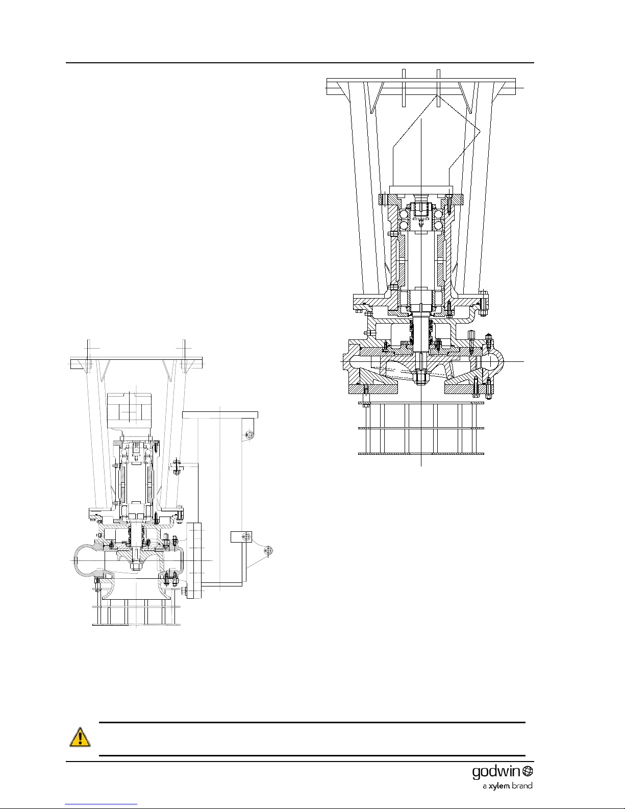
7.4 HS300 pumps
Note that dismantling and reassembly procedures refer to the item numbers in the illustration and are correct for a
directly corresponding build.
Figure 13 HS300 cross section
7.4.1 Dismantling
The HS300 arrangement differs from the rest of the range because of the extra weight and bulk of the unit. It has an
external lifting bracket. This does not require removal for maintenance tasks such as wear plate, impeller or mechanical
seal replacement.
1. Disconnect and remove all hydraulic and discharge piping and the hydraulic motor from the pump.
2. Remove the two plugs (51) from the bearing and seal chambers and drain the oil.
Page 17

Book No.: 95-0014-0000/A OPERATOR
Issue: 06 HANDBOOK
Page 17 of 30
3. Using suitable lifting gear rotate the whole unit 90° until it is resting with the shaft horizontally and th e pump mo unti ng
foot towards the ground.
4. Remove the 4 off nuts, bolts and washers (81, 74 & 62) holding the strainer to the frame.
5. Support the strainer (10) and remove the 8 off nuts, bolts and washers (81, 74 & 62) holding it to the strainer support
(9). Slide the strainer out sideways from the frame.
6. Steady the strainer support (9) and remove the 4 off nuts, & washers (81 & 74) holding it to the front cover (2). Ease
the strainer support forwards until access can be gained to the nuts holding the front cover to the pump body (1). Let
it rest on the front cover.
7. Remove the 4 off nuts and washers (81 & 74) holding the front cover to the pump body. After removal attach suitable
lifting gear to the front cover and loose strainer support. Fit 4 off M12 x 45 (minimum length) screws to the holes in
the front cover and jack it (complete with front wear plate and loose strainer support) clear of the pump body (1).
Remove this assembly sideways from the frame.
8. Remove the loose strainer support from around the front cover. The front wear plate (5) and the front of the impeller
(3) may now be inspected for wear or damage. If necessary, the front wear plate can be detached from the front
cover by removing the retaining nuts and washers (72 & 80).
9. Inspect the hydraulic motor end of the shaft. If there are two flats on the top diameter, then an anti-rotation tool is
available to aid in further dismantling. If there are no flats then a suitable block of wood must be wedged between an
impeller blade and the pump body discharge to prevent rotation. Fit the anti-rotation tool or wedge the impeller.
10. Remove the cover (item 19 - 80mm A/F) in the centre of the impeller (3) to expose the retai ning scr ew (64).
11. Knock down the tab on the tab washer (18) and slacken the retaining screw (64) to remove the tension. Do not undo
by more than one or two turns. The impeller will be removed later in the procedure. If the impeller was wedged in
position, remove the wedge.
NOTE: - If only the mechanical seal requires replacement carry out instructions 15 to 22 at this point and then
reassemble.
12. Return the frame and remainder of the pump to the upright position. Support the bolted in cross member whilst
removing its fastening bolts, nuts and washers (105, 107, 108 & 109). Remove the cross member.
13. Remove the 8 off nuts and washers (81 & 74) attaching the bearing bracket and adaptor assembly to the pump body
(1).
14. Attach suitable lifting gear to the bearing bracket and adaptor assembly and using the screws (59), jack the assembly
(including the impeller) clear of the pump body. Remove this assembly to a suitable place for further dismantling.
15. W ith the removed assembly horizontal, completely undo the impeller retaini ng screw (64) and remove the tab washer
(18) and impeller washer (16).
16. Pull the impeller (3) off the splines on the shaft (23). Note the number and size of shims on the shaft behind the
impeller for reference when re-assembling. NOTE:- The face against which the impeller is fitted is part of the
mechanical seal assembly and care must be taken not to damage it any way during further dismantling. The exposed
rear wear plate (6) can now be inspected for wear or damage.
17. If fitted remove the anti-rotation tool.
18. To remove the rear wear plate (6), remove the 6 off nuts and washers (80 & 72) securing it to the adaptor. Using the
2 off screws (61) the rear wear plate can be jacked off the adaptor.
19. 4 off socket cap screws (56) are now exposed. Undo them to remove the inboard seal seat carrier (item 4 wear
plate). Take care in removal not to damage either the seal seat attached to the back of the carrier or the seal sleeve
on the shaft.
20. Remove the 4 off screws and spring washers (57 & 71) holding the seal clamp ring (7). Push out the inboard seal
seat (12).
21. The double mechanical seal (13) is a one piec e assembly and it can now be withdrawn from the shaft.
22. The outboard seal seat carrier (11) can now be released from the adaptor (8) by undoing and removing the 4 off
socket cap screws and washers (55 & 70). The outboard sea l seat (14) can now be pushed out of the carrier (11).
23. Separate the adaptor (8) from the bearing bracket (20) assembly by undoing and removing the 8 off nuts, bolts and
washers (63, 74 & 81).
24. Undo the screws and spring washers (60 & 73) and remove the bearing cover (22) from the bearing bracket (20).
25. Press the shaft assembly out of the bearing bracket from the pump end.
26. The pump end bearing cover (21) can be removed from the bearing bracket (20) by releasing the 6 off screws and
spring washers (58 & 72).
27. Remove the spacer (28) from the bearing bracket.
28. Press the roller bearing outer race (part of 24) out of the bearing bracket.
29. Flatten the locking washers (26) tags, prevent the shaft from rotating, and unscrew the bearing locknuts (27).
30. Pull the 2 off angular contact ball bearings (25) off the shaft.
31. Pull the roller bearing inner race (part of 24) off the shaft.
32. The pump body (1) may now be removed from the lifting frame (100).
Dismantling is now complete. Inspect all part s for damage or wear.
Page 18

OPERATOR Book No.: 95-0014-0000/A
HANDBOOK Issue: 06
Page 18 of 30
7.4.2 Reassembly
New seals, O-rings and impeller retaining screw must be fitted when reassembling.
1. Heat the roller bearing inner race (part of 24) and both angular contact ball bearings (2 off 25) with a temperature
controlled bearing heater until they are a consistent 110°C. Do not overheat or allow the bearings to remain at this
temperature for longer than their fitting time.
CAUTION. Bearing races must be pressed into position and not hammered either directly or by drift. Direct
hammering will damage the bearing or rollers. Drift hammering will introduce swarf into the assembly. Either will
result in early bearing failure.
2. Once up to temperature, slide the roller bearing inner race up hard against the shaft shoulder, fit the bearing spacer
(28) and slide the angular contact ball bearings up hard onto the other shaft shoulder. Hold them in position for a
minimum of 30 seconds. The lock nuts (27) fitted without the tab washers are suitable for this purpose. This allows
the races to grip the shaft and prevent them from creeping away from the shoulder during cooling. Let the assembly
cool completely.
3. Once cool, remove the lock nuts (27), fit the locking washers (26) and refit the lock nuts. Knock up at least two tags
on the locking washers to secure.
4. Press the roller bearing outer race (part of 24) into the bearing bracket (20) leaving it about 1mm proud of the end. Fit
the bearing cover (21) with 6 off screws and spring washers (58 & 72). Tighten evenly until the cover is flat and
square against the bearing outer race. Continue tightening half a turn at a time and press the outer race fully home.
5. Press the shaft assembly into the bearing bracket from the motor end until it is clamped hard together.
6. Fit O–ring (44) to motor end bearing cover (22). Attach cover to the bearing bracket with cap head screws and spring
washers (60 & 73).
7. Fit filler elbow (85) and plug (52) to bearing cover (22) ensuring fill will be vertical when pump is fully assembled.
8. Take adaptor (8) and fit filler elbow, extension pipe, socket and plug (85, 86, 87 & 52). Ensure fill will be vertical when
pump is fully assembled. Fit 2 off drain plugs (51).
9. Press the outboard seal seat (14) into the carrier (11). Fit the O-ring (40) to the carrier and secure into the adaptor (8)
using 4 off socket cap screws and washers (55 & 70).
10. Fit the O-ring (37) to the top face of the adaptor (8). Orientate the adaptor correctly in relation to the bearing bracket
assembly so that the oil filler assembly will pass through the hole in the bearing bracket and secure them together
with 8 off bolts, nuts and spring washers (63, 74 & 81).
11. Press the inboard seal seat (12) into the carrier (4) and secure with the seal clamp ring (7) held by 4 off screws and
spring washers (57 & 71).
12. Fit the one piece double mechanical seal (13) over the shaft ensuring that the seal faces meet and the seal sleeve is
butted against the shaft shoulder.
13. Place the O-ring (38) over the inboard seal carr ier (4) spigot . Pass the carrier over the shaft taking care not to
damage the seal seat and locate it in the recess in the adaptor. Secure with 4 off cap headed screws (56).
NOTE: - The seal working lengths are obtained automatically and no setting is required.
14. Fit 6 off studs (66) to the rear wear plate (6). Position the rear wear plate and secure with 6 off nuts and spring
washers (80 & 72).
15. Press the roll pin (15) into the end of shaft (23).
16. Slide the impeller (3) onto the shaft. Temporarily fit the impeller washer (16) without an O-ring and secure with a
hand tight bolt. NOTE: - This bolt should not be the one used finally.
17. Measure the gap between the back of the impeller and the rear wear plate with feeler gauges at three positions 120°
apart. Rotate the impeller 60° and measure again. Average the readings. If it is already less than the tolerances
given in the Technical Data section, remove the impeller, add appropriate shims and refit.
18. If the hydraulic motor end of the shaft has two flats on the sides, an anti-rotation tool (available from Xylem
Dewatering Solutions) can be fitted f or the following process. If the shaft is plane ended, then a baulk of timber
wedged across the impeller blades and against some suitably rigid structure will have to be employed.
19. Tighten the impeller bolt and recheck the clearance. If outside the given tolerance, remove the impeller and add or
remove shims (30, 31, 32) as appropriate.
20. Once the correct running clearance has been achieved, remove the fastening bolt and discard. Remove the impeller
washer and fit the O-ring (42) and roll pin (17). Replace the impeller washer, fit the tab washer (18) over the roll pin
and secure all in place with the bolt (64) torqued to the value in the Technical Data section.
21. Fit the O-ring (43) to the impeller washer and screw down the impeller washer cover (item 19 – 80 A/F) fully.
22. Remove the anti-rotation tool or wedge.
23. Place the pump body (1), suitably supported from its front cover mounting face so that it’s axis vertical. Fit 8 off studs
(81) to the adaptor face. Attach suitable lifting gear to the bearing bracket/adaptor assembly. Lift the assembly,
position it over the pump body, and orientate it so that the oil fillers are over the discharge trumpet and at right angles
to the flange. Lower it into position on the pump body. Secure with 8 off nuts and spring washers (81 & 74).
24. Rotate the assembly to the horizontal.
25. Fit 4 off studs (65) to the front wear plate (5).Attach the front wear plate to the front cover (20) using 4 off nuts and
spring washers (72 & 80).
Page 19

Book No.: 95-0014-0000/A OPERATOR
Issue: 06 HANDBOOK
Page 19 of 30
26. Fit 4 off studs (67) every other hole in the pump body. Fit 4 off studs (68) in the remaining holes. Pass the front cover
assembly over the studs and secure with 4 off nut and spring washers (74 & 81) on the shorter studs.
27. Measure the clearance between all impeller vanes and the front wear plate. Take the average and compare with the
running clearance given in the Technical Data section. If required add or remove shims (33, 34, 35, 36) as
appropriate.
28. Pass the strainer support (9) over the front cover and studs, locating it so that the larger holes in the support fit over
the previously fitted nuts. Secure in place with 4 off nuts and spring washers (74 & 81).
29. Attach the strainer (10) to the strainer support with 8 off nuts, bolts, and washers (81, 74 & 62).
30. Rotate the whole assembly so that the shaft is vertical (strainer down) Tilt the lifting bracket (100) to angle of about
20° with the open side up and lift the pump assembly into place, allowing the frame to return to the vertical as it is
done. Position within the bracket so that all securing bolts can be fitted. Secure with the appropriate nuts, bolts and
washers.
NOTE: - Tolerances between the pump assembly and the lifting bracket can be several millimetres. It is recommended
that the pump foot is fitted directly to the bracket and space elsewhere is made up with washers.
Assembly is now complete, but before attaching the hydraulic lines, the unit must be filled with oil in both the bearing
bracket and seal chambers.
7.5 HS100NC & HS150NC Pumps
The HS100NC and HS150NC pumps share many parts with the 10022 and15022
pumps, differing only in the volute, impeller and associated items. Therefore the
method of dismantling and reassembly follow almost exactly the same procedures
(see section 7.2) except for the following:-
7.5.1 Dismantling
After removing the strainer, the impeller must be loosen ed sl ightly before extracting
the bearing bracket assembly (including the impeller) from the pump body.
Loosening the impeller will require the following tool in addition to a standard Allen
key required to remove the impeller locking screw :
½” drive Hexagon head (Allen bit) 12mm x 65mm long (Figure 15
).
Remove access plug from pump body (shown in Figure 14) and insert an antirotation bar to prevent the impeller rotating.
Remove the impeller retaining cap screw (Figure 16) and washer (see Figure 17).
The impeller will still be retained by the friction fit of the sleeve between the shaft
and the impeller. Even if it this is dislodged the impeller will be retained within the
body.
Figure 14 Typical HS100NC pump
Figure 15 1/2" drive Hexagon
head (Allen bit) 12mm x 65mm
Figure 16 Removal of impeller
retaining cap screw
65mm
Page 20
OPERATOR Book No.: 95-0014-0000/A
HANDBOOK Issue: 06
Page 20 of 30
Figure 17 Typical HS100NC & HS150NC cross sectional view
To break the friction fit between the impeller sleeve and the shaft, the adjustment
screw is turned anticlockwise (it is left hand threaded -Figure 18 ) using the 65mm
long Allen key (Figure 15). Turn sufficiently until it contacts the shaft and just breaks
the engagement.
Refit the impeller washer and screw hand tight as a security measure. This will
ensure that the impeller is retained on the shaft when the bearing bracket assembly
is removed from the volute.
The impeller is then removed from the shaft be undoing and removing the hand
tight impeller screw and washer. The impeller , impeller sleeve and adjustment
screw can then be removed.
All remaining dismantling procedure follow those in section 7.2.1.
1
4
5
2
3
1. Impeller
2. Impeller sleeve
3. Adjustment screw
4. Impeller screw
5. Washer
Figure 18 Detaching impeller from shaft
Figure 19 Removal of impeller and sleeve
Page 21

Book No.: 95-0014-0000/A OPERATOR
Issue: 06 HANDBOOK
Page 21 of 30
7.5.2 Reassembly
7.5.2.1 GUIDE PIN FITTING
The HS100NC and HS150NC are fitted with a ’chopper’ insert ring. It is critical to efficient operation of the
pump that the guide pin used is fitted correctly.
Place impeller on flat surface – blades up.
Locate insert ring on the impeller, ensure the insert ring is
centralized on the impeller (Figure 20).
Figure 20 Locating insert ring on impeller
The guide pin comprises of three items, lip (1), cap screw (2) and nut (3)
(Figure 21).
Figure 21 Lip, cap screw and nut
Assemble the cap screw into the lip and apply non setting thread lock
compound to the cap screw (Figure 22).
Figure 22 Applying non-setting thread lock compound
Place nut on to the cap screw and fit the assembly in to the
locating slot (Figure 23).
Figure 23 Locating guide pin assembly into insert ring
Impeller
Insert Ring
Page 22

OPERATOR Book No.: 95-0014-0000/A
HANDBOOK Issue: 06
Page 22 of 30
Align the guide pin lip with the centre boss of the impeller
(Figure 24).
Figure 24 Aligning the guide pin lip with the centre boss of the impeller
Hold the lip tip firmly against the centre of the impeller boss
and tighten the cap screw with Allen wrench until it is held in
place (Figure 25).
Figure 25 Tightening the cap screw with Allen wrench
Place the complete assembly into a vice and then tighten the
cap screw using a torque wrench (Figure 26) to the correct
torque. Check cap screw size and see Technical data section
for detail.
Figure 26 Tightening the cap screw with torque wrench
Page 23

Book No.: 95-0014-0000/A OPERATOR
Issue: 06 HANDBOOK
Page 23 of 30
7.5.2.2 IMPELLER FITTING
The impeller is fitted to the tapered shaft by
means of a tapered sleeve with an adjusting
screw locked onto the shaft with a screw and
washer (Figure 27).
Figure 27 Impeller & fittings
Inspect the end of the shaft for any damage, remove any burrs and polish off any flaws with fine emery cloth.
Lightly apply grease film to the shaft end and remove any surplus grease from the taper.
Lightly apply a grease film to the inside of the tapered sleeve and remove any surplus grease.
Lightly grease the threads of the adjustment screw if needed, remove any surplus grease.
NOTE! The impeller can become loose. Remove any surplus grease from the conical and cylindrical surfaces of the
shafts and sleeves.
Important: Before any assembly begins rotate the adjustment screw until
it is level with the sleeve (Figure 28). This is the initial setting up point for
the impeller.
The adjustment screw has a left hand thread. Turning it clockwise
moves it outward and turning it anti-clockwise moves it into the sleeve.
The adjustment screw is used to adjust the clearance between the
impeller and the insert ring (wear plate).
Figure 28 Taper sleeve and adjustment screw
Insert the taper sleeve (2) complete with adjustment screw (3) in its correct
position into the impeller (1) (Figure 29).
Lightly lubricate the impeller cap head screw.
Load impeller complete as above on the shaft.
Insert the impeller cap head screw with its plain washer and hand tighten, this
will ensure the impeller is in the correct position on the taper, and prevent the
impeller falling off during further assembly.
Continue with assembly, attaching the bearing bracket/impeller assembly to the
volute.
Figure 29 Impeller, sleeve and adjustment screw
1. Impeller
2. Impeller sleeve
and adjustment
screw
3. Impeller screw
4. Washer
3
2
1
4
1
2 & 3
Page 24

OPERATOR Book No.: 95-0014-0000/A
HANDBOOK Issue: 06
Page 24 of 30
7.5.2.3 ADJUSTING IMPELLER FRONT CLEARANCE
Unscrew and remove the impeller cap screw and flat washer.
Using the Hexagon head (Allen bit) 12mm x 65mm long with extension bars (Figure 30 if needed) turn the adjustment
screw clockwise by hand until the impeller firmly makes contact with the wear plate (insert ring).
Figure 30 Hexagon head (Allen bit) and extension bar
Remove the Hexagon head (Allen bit), reach into the pump inlet and check the impeller cannot be rotated from this
position by hand.
Insert the anti-rotation bar through the access plug in the pump body to
prevent the impeller rotating.
Fit the lubricated impeller cap screw and flat washer.
Tighten the impeller cap screw to the correct torque using a torque
wrench, and then turn it an extra 1/8 turn (45°) with a wrench or bar.
(Check cap screw size and see Section 10.4
Table 2 for values ).
Using feeler gauges reach into the pump inlet and measure the
available impeller to wear plate (insert ring) clearance.
The minimum acceptable running clearance is 0.2mm (0.008”)
Important: Remove the anti-rotation bar and replace access plug in the
pump body.
Figure 31 Cross-section of pump inlet
Page 25

Book No.: 95-0014-0000/A OPERATOR
Issue: 06 HANDBOOK
Page 25 of 30
8 WARRANTY
Unless special arrangements have been agreed and signed by both partie s Xylem Dewatering Solutions will apply the
following policy over defects found after delivery.
We will make good, by repair or the supply of a replacement, defects which, under proper use, appear in the goods within
a period of twelve calendar months after the goods have been delivered
(1)
and arise solely from faulty design (other than
a design made, furnished or specified by you for which we have disclaimed responsibility in writing), materials or
workmanship: provided always that defective parts have been returned to us if we shall have so required. We shall refund
the cost of carriage on such returned parts and the repaired or new parts will be delivered by us free of charge.
Our liability under this clause shall be in lieu of any warranty or condition implied by law as to the quality or fitness for any
particular purpose of the goods, and save as provided in this clause we shall not be under any liability, whether in
contract, tort or otherwise, in respect of defects in goods delivered or for any injury
(2)
, damage or loss resulting from such
defects as from any work done in connection therewith.
(1)
For export orders, within a period of twelve calendar months after the goods have been delivered or, if delivery is
delayed by reason of customer instructions or lack of instructions, within a period of 18 months after the goods have
been notified as ready for despatch (whichever period expires the earlier)
(2)
For UK orders, other than personal injury caused by our negligence as defined in Section 1 of the Unfair Contract
Terms Act, 1977.
9 FAULT FINDING
If possible fit a suction and pressure gauge to assist fault finding and check pump rating
POSSIBLE CAUSE
FAULT
REMEDY
Pump dose
not discharge
sufficient
head
Repeated
mechanical
seal failure
High oil
temperature
Milky
hydraulic oil
Aerated
hydraulic oil
Pump end blocked or worn
√ √
Clean/repair pump
Discharge hose kinked or blocked
√ √
Clear obstruction
Worn hydraulic motor or pump
√ √
Replace
Pump end running slow √
Check prime mover speed.
Check hydraulic oil flow from
control end under load
Blocked return filter element
√
Renew
Return hose too long √
Check with table for maximum
hose lengths
Hose coupling failing to operate
properly (if quick release couplings
are employed)
√ √ Clean, repair or replace
Insufficient oil √ √
Fill reservoir or increase in size
Pressure or return line blocked
√
Clean, repair or replace
Water contamination causing
emulsification
√
Drain all system oil
Check reservoir for water entry
Pump mechanical seal failure –
replace
Page 26

OPERATOR Book No.: 95-0014-0000/A
HANDBOOK Issue: 06
Page 26 of 30
10 TECHNICAL DATA
10.1 HS80, HS100, HS100-SG, HS103, HS150, HS150V & HS150V-SG
Pumps
PUMP HS80 HS100 HS100-SG HS103 HS150
HS150V
HS150V-SG
Rotation
ACW looking at
impeller from
suction end
See Note 1
ACW looking at impeller from suction end
Max pump
speed
rpm
2600 2400 2400 2200 1500 2400
Max head
m (ft)
25 (82)
35 (115) 52
20 (66)
33 (108)
Max flow
m3/hr
(Imp.
gpm)
80 (293) 200 (733) 175 230 400 (1466) 432 (1590)
Nominal solids
capacity
Ø mm (“)
40 (1.575) 45 (1.77) 75 65 (2.56) 127 (5)
Impeller
clearance (front
and rear)
mm (“)
0.50 – 0.63 (0.020 – 0.025)
0.4 – 0.5
(0.015 – 0.020)
Rear 0.50 – 0.63
(0.020 – 0.025)
Front
N/A
Impeller screw
(nut) torque
Nm
(lbs.ft)
98 (72) 197 (145)
Mechanical
seal sett ing
dimension
mm (ins)
N/A N/A N/A
Mechanical
seal oil
N/A. Seal is fed
from hydraulic
system
Any SAE 20/20 or Biopus 46 Biodegradeable
Bearing bracket
oil
N/A SAE 20/20
Discharge
connection
Female 3”NPT
or 3”BSP
Female
4”NPT or
4”BSP
Flanged 4”
ASA150 or
4” BS10
Table D
Female
4”NPT or
4”BSP
Female 6”NPT
or 6”BSP
150V: -Female 6”NPT
150V-SG: -
Flanged 6”
ASA150
Bearing bracket
leakage
connection size
¼”BSPT female
3/4” NPSM for ASA150 or NPT units;
3/8” BSPT female for BS10 or BSP units
Hydraulic motor interface
Flange
SAE ‘A’ 2 bolt
SAE ‘B’ 2 bolt
SAE ‘C’ 4 bolt
Shaft
1 1/8” x 24 straight
sided serrations to
BS2059: 1953
SAE ‘A’ spline
Ø15.5
9 teeth 16/32 DP
SAE spline
Ø21 13 teeth
16/32 DP
SAE spline 1 ¼” 14
teeth
12/24 DP
Xylem Dewatering Solutions supplied motors
Drive pressure
bar (psi)
280 (4060)
250 (3625)
Flow & Return
connection size
(supplied with quick
release couplings
on 8022, 10022 &
10022)
½”BSPT female 3/4”BSPT female
Bearing
leakage
connection size
(supplied with quick
release couplings
on 8022, 1002 &
15022)
¼”BSPT female 3/8”BSPT female
Pump leakage
connection size
N/A N/A
Hydraulic oil
Fluid conforming to ISO 32-46
Standard Biodegradeable
Shell Tellus Oil 27 Shell Naturelle Fluid HF-E 32
Shell Naturelle Fluid HF-E 46
Texaco Rando HD 32 or 46 Texaco Hydra 46
Texaco Rando HDZ 32 or 46 Terrasolve Envirologic 132
Max flow
l/min @
rpm
12.0 @ 2600 36 @ 2300 55.9 @ 1670 100@2000
NOTES. 1.Exercise particular caution with these units. Early 10022 are CW looking at impeller from suction end; later
units are ACW.
Page 27

Book No.: 95-0014-0000/A OPERATOR
Issue: 06 HANDBOOK
Page 27 of 30
10.2 HS150HH, HS200, HS200-SG, HS250 & HS300 Pumps
PUMP HS150HH HS200 HS200-SG HS250 HS300
Rotation
ACW looking at impeller from suction end
Max pump
speed
rpm
2000 1800
Max head
m (ft)
100 (328)
40 (131)
63
Max flow
m3/hr
(Imp.
gpm)
275 (1000) 750 (2750) 700 760 (2785) 1368
Nominal solids
capacity
Ø mm
(“)
35 (1.375) 75 (2.95) 79 75 95
Impeller
clearance (front
and rear)
mm (“)
0.50 – 0.63 (0.020 – 0.025) 0.50 – 0.63 (0.020 – 0.025)
Impeller screw
(nut) torque
Nm
(lbs.ft)
633 (467) 240
Mechanical
seal sett ing
dimension
mm
(ins)
34 ± 0.3 (1.339 ± 0.012)
N/A
Mechanical
seal oil
SAE 20/20 or Bioplus 46 Biodegradeable
Bearing bracket
oil
SAE 20/20
Discharge
connection
Flanged
6”ASA 150
Flanged
8”
ASA150
Flanged 8” BS10 Table D
Flanged 10”
BS10 Table D
Flanged 12”
ASA150
Hydraulic motor interface
Flange
SAE ‘D’ 4 bolt
SAE ‘C’ 4 bolt
SAE ‘D’ 4 bolt
Shaft
SAE spline 1
¾”
13 teeth
8/16DP
SAE spline 1 ¼” 12/24 DP
SAE spline 1 ¾”
13 teeth
8/16DP
14
teeth
17 teeth
Xylem Dewatering Solutions supplied motors
Drive pressure
bar
(psi)
N/A 250 (3625) 310 (4495)
Flow & Return
connection size
(supplied with quick
release couplings
on HS80, HS100 &
HS150)
1 1/4”BSPT female
Twin 1 1/2
”BSPT
female
Bearing
leakage
connection size
(supplied with quick
release couplings
on HS80, HS100 &
HS150)
½” BSPT female
3/4” BSPT
female
Pump leakage
connection size
7/8”-14 UNF
Hydraulic oil
Fluid conforming to ISO 32-46
Standard Biodegradeable
Shell Tellus Oil 27 Shell Naturelle Fluid HF-E 32
Shell Naturelle Fluid HF-E 46
Texaco Rando HD 32 or 46 Texaco Hydra 46
Texaco Rando HDZ 32 or 46 Terrasolve Envirologic 132
Max flow
l/min
@ rpm
N/A 100 @ 2000 320@1800
Page 28
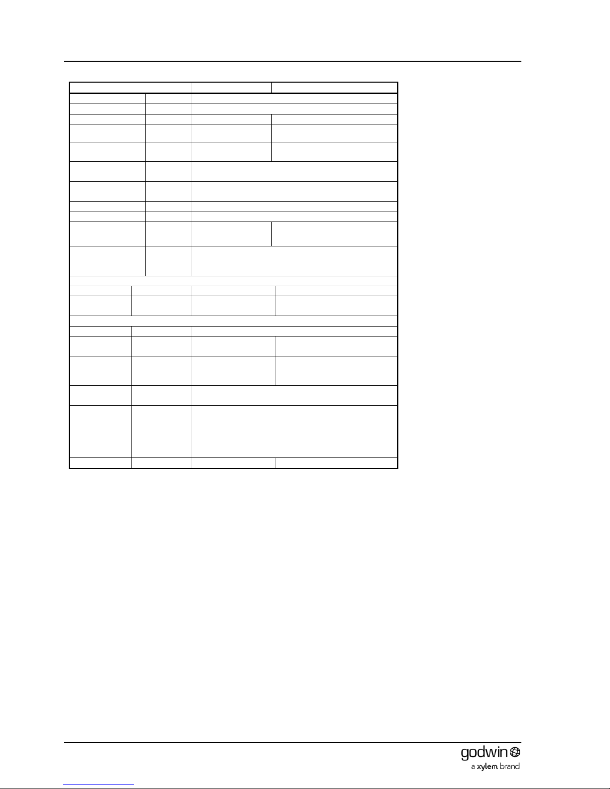
OPERATOR Book No.: 95-0014-0000/A
HANDBOOK Issue: 06
Page 28 of 30
10.3 HS100NC & HS150NC Pumps
PUMP
HS100NC
HS150NC
Rotation ACW looking at impeller from suction end
Max pump speed
rpm
2200
Max head
m (ft)
40 (131)
52 (170)
Max flow
m3/hr (Imp.
gpm)
225 (825) 370 (1356)
Nominal solids
capacity
Ø mm (“)
35 (1.37) 42 (1.65)
Impeller clearance
(front and rear)
mm (“)
0.2mm to 0.8mm (0.008” to 0.031”)
Impeller screw
(nut) torque
Nm (lbs.ft)
76 (56)
Mechanical seal oil
N/A. Seal is fed from hydraulic system
Bearing bracket oil
N/A
Discharge
connection
4” NPT or 4” BSP 6” NPT or 6” BSP
Bearing bracket
lea
kage connection
size
3/4” NPT for NPT units or 3/8”BSPP for BSP units
Hydraulic motor interface
Flange SAE ‘B’ 2 bolt
SAE ‘C’ 4 bolt
Shaft
SAE ‘B’ spline
13 teeth 16/32 DP
SAE ‘C’spline
14 teeth 12/24 DP
Xylem Dewatering Solutions supplied motors
Drive pressure
bar (psi)
250 (3625)
Flow & Return
connection size
3/4”BSPT female 1”BSPT female
Bearing
leakage
connection size
3/8”BSPT female 1/2”BSPT female
Pump leakage
connection size
N/A
Hydraulic oil
Fluid conforming to ISO 32-46
Standard Biodegradeable
Shell Tellus Oil 27 Shell Naturelle Fluid HF-E 32
Shell Naturelle Fluid HF-E 46
Texaco Rando HD 32 or 46 Texaco Hydra 46
Texaco Rando HDZ 32 or 46 Terrasolve Envirologi c 132
Max flow
l/mi n @ rpm
60 @ 2000
100 @ 2000
Page 29
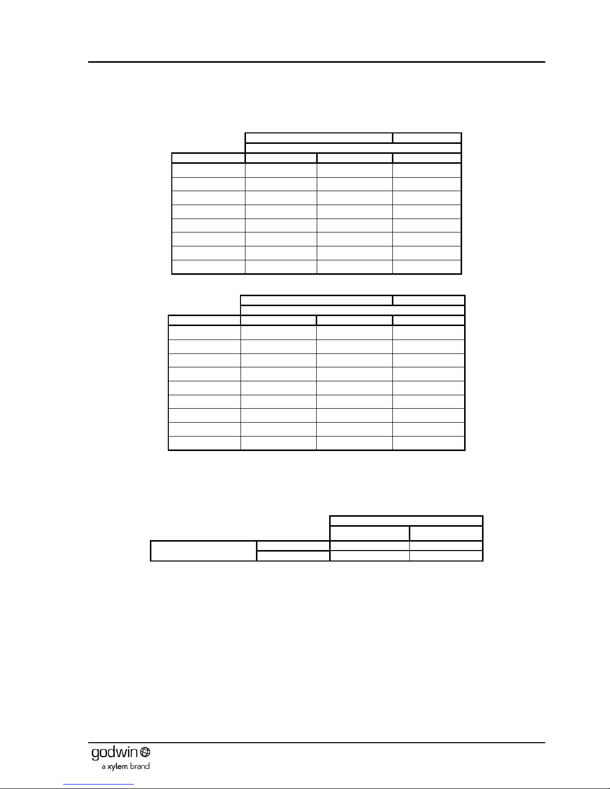
Book No.: 95-0014-0000/A OPERATOR
Issue: 06 HANDBOOK
Page 29 of 30
10.4 Fastener Torques
The following tables give the recommended tightening torques for general purpose metric and UNC fasteners. They are to be
used only when the joint is metal to metal (i.e. no joints or gaskets) and no special figures (e.g. for impeller retaining bolts) have
been quoted.
Table 2 Metric
Fasteners
Steel
Stainless
Torque (N-m)
Thread Size
Nuts & Bolts
Nuts on Studs
All
M6 x 1.0 11.7 4.6 9
M8 x 1.25 28 11 22
M10 x 1.5 56 22 44
M12 x 1.75 98 38 76
M16 x 2.0 244 95 187
M20 x 2.5 476 185 364
M24 x 3.0 822 320 629
M30 x 3.5 1633 633 1240
Table 3 UNC
Fasteners
Steel
Stainless
Torque (N-m)
Thread Size
Nuts & Bolts
Nuts on Studs
All
¼” - 20 13.5 5.4 10.5
5/16” – 18 27.1 10.5 21.0
3/8” – 16 48.8 20 37.8
7/16” – 14 74.6 30 57.8
½” – 13 122 48 94.6
5/8” – 11 237.3 95 183.9
¾” – 10 420.4 167 325.8
7/8” – 9 664.4 266 514.9
1” - 8 1003 401 777.3
Table 1 figures are for Metric fasteners to BS3692. Steel fasteners: - Grade 8.8 for bolts, Grade 4.6 for studs, Grade 10 for nuts;
Stainless Steel fasteners: - Grade A2 or A4, Class 70 or 80.
Table 2 figures are for UNC fasteners to BS1768 Steel fasteners: -Grade S and Grade 3 for nuts; Stainless Steel fasteners: Grade A2.
If steel fasteners are of dissimilar condition then the figures Table 1 or Table 2 must be multiplied by those in Table 3.
Table 4 Correction factors
PLATING CONDITION OF BOLT
BLACK ZINC
PLATING CONDITION OF
NUT
BLACK
1.0
0.9
ZINC
0.9
0.8
Page 30

OPERATOR Book No.: 95-0014-0000/A
HANDBOOK Issue: 06
Page 30 of 30
NOTES
 Loading...