

Godrej Appliances Eyetrace Elite ET 8L1E User's Installation And Operation Manual
USER MANUAL
ET 8L1E

DVR User’s Installation and Operation Manual
Welcome
Thank you for purchasing our DVR.
This manual is designed to be a reference tool for the installation and operation of your
system.
Here you can find information about this series, DVR features and functions as well as a
detailed menu tree.
Before installation and operation, please read the following safeguards and warnings
carefully!
Important Safeguards and Warnings:
1. Do not place heavy objects on DVR.
2. Do not let any solid or liquid fall into or infiltrate the DVR.
3. Please brush printed circuit boards (PCBs), connectors, fans, machine box and so on
regularly.
4. Before the dust cleaning, please Switch OFF the power supply and unplug it.
5. Do not disassemble or repair the DVR by yourself. Do not replace the components by
yourself.
Environment:
1. Please place and use the DVR between 0 – 40 degree Celsius. Avoid direct sunlight. Stay
away from heat source.
2. Do not install the DVR in damp environment.
3. Do not use the DVR in smoky and dusty environment.
4. Please ensure that the DVR level installation is in a stable workplace.
5. Please install in ventilated place. Keep the vent clean.
6. Use within the rating input and output scope.

Table of Contents
1. Product Introduction.............................................................................................................5
1.1 Product overview................................................................................................................5
1.2 Main functions ...................................................................................................................5
2. DVR Description ....................................................................................................................6
2.1 Description of front panel...................................................................................................6
2.2 Description of rear panel.....................................................................................................6
2.3 Hard Disk Installation..........................................................................................................7
3. Basic operation......................................................................................................................7
3.1 Turn on................................................................................................................................7
3.2 Turn off................................................................................................................................7
3.3 Login....................................................................................................................................7
3.4 Preview................................................................................................................................8
3.5 Desktop shortcut menu.......................................................................................................8
3.5.1 Main menu.......................................................................................................................8
3.5.2 Video playback.................................................................................................................9
3.5.3 Record Mode..................................................................................................................10
3.5.4 Alarm output..................................................................................................................10
3.5.5 PTZ control.....................................................................................................................11
3.5.6 Colour Settings...............................................................................................................14
3.5.7 TV Adjust........................................................................................................................14
3.5.8 Logout............................................................................................................................14
3.5.9 Window switch...............................................................................................................14
4. Main Menu..........................................................................................................................14
4.1 Main menu navigation......................................................................................................14
4.2 Recording function............................................................................................................16
4.2.1 Recording Configuration................................................................................................16
4.2.2 Video playback...............................................................................................................17
4.2.3 Video backup..................................................................................................................17
4.3 Alarm Function..................................................................................................................17
4.3.1 Motion Detect................................................................................................................18
4.3.2 Video Blind.....................................................................................................................19
4.3.3 Video Loss......................................................................................................................19
4.3.4 Alarm input.....................................................................................................................19
4.3.5 Alarm output..................................................................................................................19
4.3.6 Abnormality....................................................................................................................20
4.4 System setup.....................................................................................................................20
4.4.1 General setup.................................................................................................................20
4.4.2 Encode setup..................................................................................................................21
4.4.3 Network setup................................................................................................................21
4.4.4 Network service.............................................................................................................22
4.4.5 GUI display.....................................................................................................................24
4.4.6 PTZ setup........................................................................................................................24
4.4.7 Serial port setup.............................................................................................................25
4.4.8 Tour setup......................................................................................................................25
4.5 Management tools............................................................................................................25
4.5.1 Hard disk management..................................................................................................25

4.5.2 User management..........................................................................................................26
4.5.3 Online user.....................................................................................................................27
4.5.4 TV Adjust........................................................................................................................27
4.5.5Auto maintenance...........................................................................................................28
4.5.6 Resume default..............................................................................................................28
4.5.7 Upgrade..........................................................................................................................28
4.6 System information...........................................................................................................29
4.6.1 Hard disk information....................................................................................................29
4.6.2 Code stream statistics....................................................................................................29
4.6.3 Log information..............................................................................................................29
4.6.4 Edition information........................................................................................................29
4.7 Shut down system.............................................................................................................29
5. FAQs and Maintenance.......................................................................................................30
5.1 FAQs..................................................................................................................................30
5.2 Maintenance.....................................................................................................................34
Appendix 1.Remote controller operation ..............................................................................34
Appendix 2.Mouse Operation.................................................................................................35
Information on E-waste handling and management..............................................................36
Warranty.................................................................................................................................37

1. Product Introduction
1.1 Product overview
The series DVR is designed especially for security and defense field which is outstanding
Digital Surveillance product. It introduces embedded LINUX operating system which is more
stable. It introduces standard H.264 video compression format and G 711A audio
compressed format which ensures the high quality image, low error coding ratio and single
frame playing. It introduces TCP/IP network technology which achieves the strong network
communication ability and telecommunication ability. The series DVR can be used
individually or online applied as a part of a safety surveillance network. With the
professional network video surveillance software it achieves the strong network
communication ability and telecommunication ability. The series DVR can be applied in the
bank, telecom, electric power system, judicial system, factory, storehouse, water
conservancy and so on.
1.2 Main functions
Real-time surveillance
· Analog interface and VGA interface (VGA interface is equipped selectively).
· Surveillance function through monitor or display.
Storage
· Special storage format which ensures the data safety.
Compression
· Real time compression which ensures the audio and video signal stable
synchronization.
Backup
· Through SATA interface and USB interface such as USB equipment, removable hard
disk and so on.
· Through net download the files in the hard disk.
Playback
· Individual real time video recording as well as searching, playback, network
surveillance, recording check, downloading and so on.
· Multi-Playback mode zooms at arbitrary region.
Net operating
· Through net tele-surveillance in the real time.
· Tele-PTZ control.
· Tele-recording and real time playback.
Alarm linkage

· Multi-route relay output which is convenient for the alarm linkage and light control
Screen
To
Power ON/OFF
the s
creen
IR receiver
Receive signal from remote control.
ESC Press
it to exit from the inferior menu
MENU
Press this key to
view
the main menu.
Mouse
To connect USB mouse
Video Input
Standard BNC port connected with the Camera.
Video output
Connected with the video input of the monitor.
VGA
VGA video signal output port connected with a VGA port of a
Audio output
Connected with earphone or cable speaker.
Audio input port
Connected to audio input device.
and the sort.
· Protecting circuits at the alarm input and output interface which protects the main
machine from damage.
Communication interface
· RS485 interface which fulfills the PTZ control.
· Standard Ethernet network interface which fulfills the telecommunication function.
Intelligent operating
· Mouse action function.
· Fast copy and paste operating for the same setting.
2. DVR Description
2.1 Description of front panel:
LED Indications To show the working status of the DVR.
"REC” is recording indicator; "POW” is
power indicator;
REC Press it to view record mode menu.
and return to the superior menu.
Direction & confirm Keys In menu mode, select the listed options
upward/ downward/ leftward/
rightward; In PTZ, control the dome to
upward/downward/ rotate/leftward/
rightward. Enter key confirms the
selection and operation.
USB2.0 To connect Backup Device
2.2 Description of rear panel:
Name Description
computer monitor.

“485” (AB) port
RS485, it can connect PTZ or decoder, and can Control PTZ via the
panel, mouse, remote control and network.
NET
RJ-
45 network port connected to network cable and used for
Power
Power input is DC 12V/2
A.
USB port Connected to USB Pen-drive or mouse and used for system
software upgrade or video file backup
remote browse or control.
2.3 Hard Disk Installation
· Take off the cover
· Fix the HDD to the housing with help of screws
· Fix the DVR cover
3. Basic operation
3.1 Turn on
Plug the power supply and turn on the power supply switch. Power supply indicator light
indicates “turning on” of the video recorder. After the startup you will hear a beep. The
default setting of video output is multiple-window output mode. If the startup time is within
the video setting time, the timing video recording function will start up automatically. Then
the corresponding channel is shining and the DVR is working normally. Note:
1. Make sure that the input voltage corresponds with the switch of the DVR power supply.
2. Power supply demands: 220V ±10% /50Hz.
3. Suggest using the UPS to protect the power supply under allowable conditions.
3.2 Turn off
There are two methods to turn off the DVR. Entering [main menu] and choosing [turn off] in
the [turn off the system] option is called soft switching. Pressing the power supply switch is
called hard switching. Illumination:
· Auto resume after power failure. If the DVR is shut down abnormally, it can
automatically backup video and resume previous working status after power failure.
· Replace the hard disk. Before replacing the hard disk, the power supply switch in the
rear panel must be turned off.
· Replace the battery. Before replacing the battery, the setting information must be
saved and the power supply switch in the real panel must be turned off. The DVR
uses button battery. The system time must be checked regularly. If the time is not
correct you must replace the battery, we recommend replacing the battery every
year and using the same battery type.
Note: The setting information must be saved before replacing the battery, otherwise,
information will be lost.
3.3 Login
When the DVR boots up, the user must login and the system provides the corresponding
functions with the user purview. There are two user settings. The names are 'admin' and
'guest'. These names have no password. 'Admin' is the super user purview; and 'Guest'
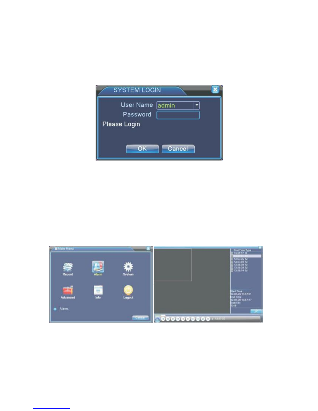
permissions are preview and video playback. User 'admin' and 'guest' passwords can be
revised, while their permissions can’t be revised. Password protection: If the password is
continuous wrong three times, the alarm will start. If the password is continuous wrong five
times, the account will be locked. (The account can be unlocked through reboot or after half
an hour, the account will be unlocked automatically). For your system security, please
modify your password after first login.
Picture 3.1 Login
3.4 Preview
You can right click mouse to choose to switch between the windows. The system date, time
and channel name are shown in each viewing window. The surveillance video and the alarm
status are shown in each window.
3.5 Desktop shortcut menu
In preview mode you can right click mouse to get a desktop shortcut menu. The menu
includes: main menu, video playback, video control, alarm output, PTZ control, color setup,
TV adjust, shut down system, window switch.
3.5.1 Main menu
When you login, the system main menu is shown as below.
Picture 3.2 Main menu Picture 3.3 video playback
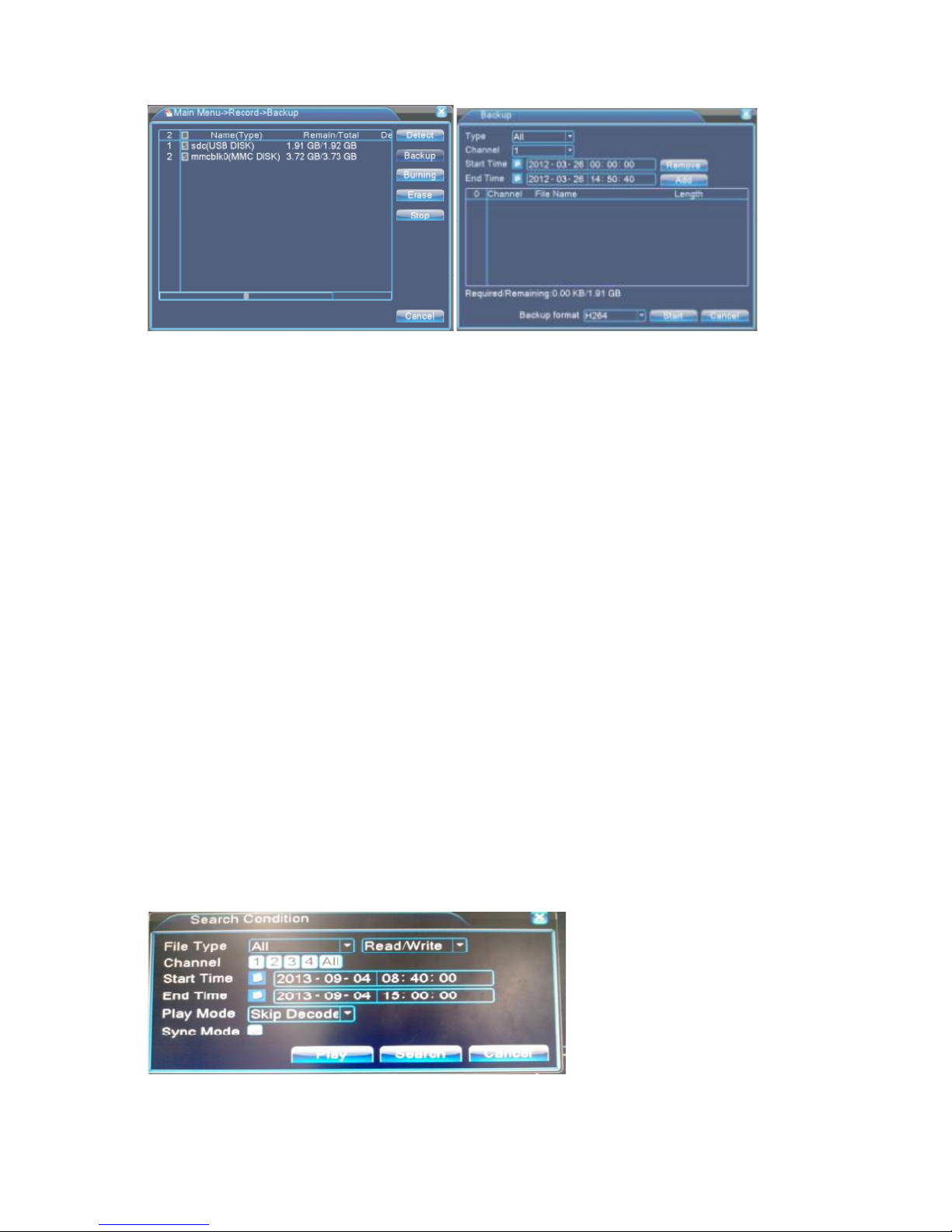
Picture 3.4 detect the storage Picture 3.5 Recording backup
3.5.2 Video playback
There are two methods for you to play the video files in the hard disk.
1. In the desktop shortcut menu.
2. Main menu > video recording > video playback.
Note: The hard disk that saves the video files must be set as read-write or read-only state.
[Listed files] Look up the listed files that accord with the searching criteria.
[File information] Look up the found file information.
[File backup] Backup the chosen file. Click the button and operate as followed.
Note: The storage must be installed before the file backup. If the backup is terminated,
the already existing backup can playback individually.
Detect: Detect the storage connected with the DVR such as hard disk or universal disk.
Erase: Choose the file to delete and click 'Erase' to delete the file.
Stop: Stop the backup.
Backup: Click 'Backup' button and the dialog box is popped up. You can choose the backup
file according to type, channel and time.
Remove: Clear the file information.
Add: Show the file information satisfying the set file attributes.
Start/Pause: Click the 'Play' button to start the backup and click the 'Pause' button to stop
the backup.
Cancel: During backup you can exit the page layout to carry out their functions.
[File searching]: Search the file according to the searching parameter.
Picture 3.6 File searching
File type: Set the searching file type.
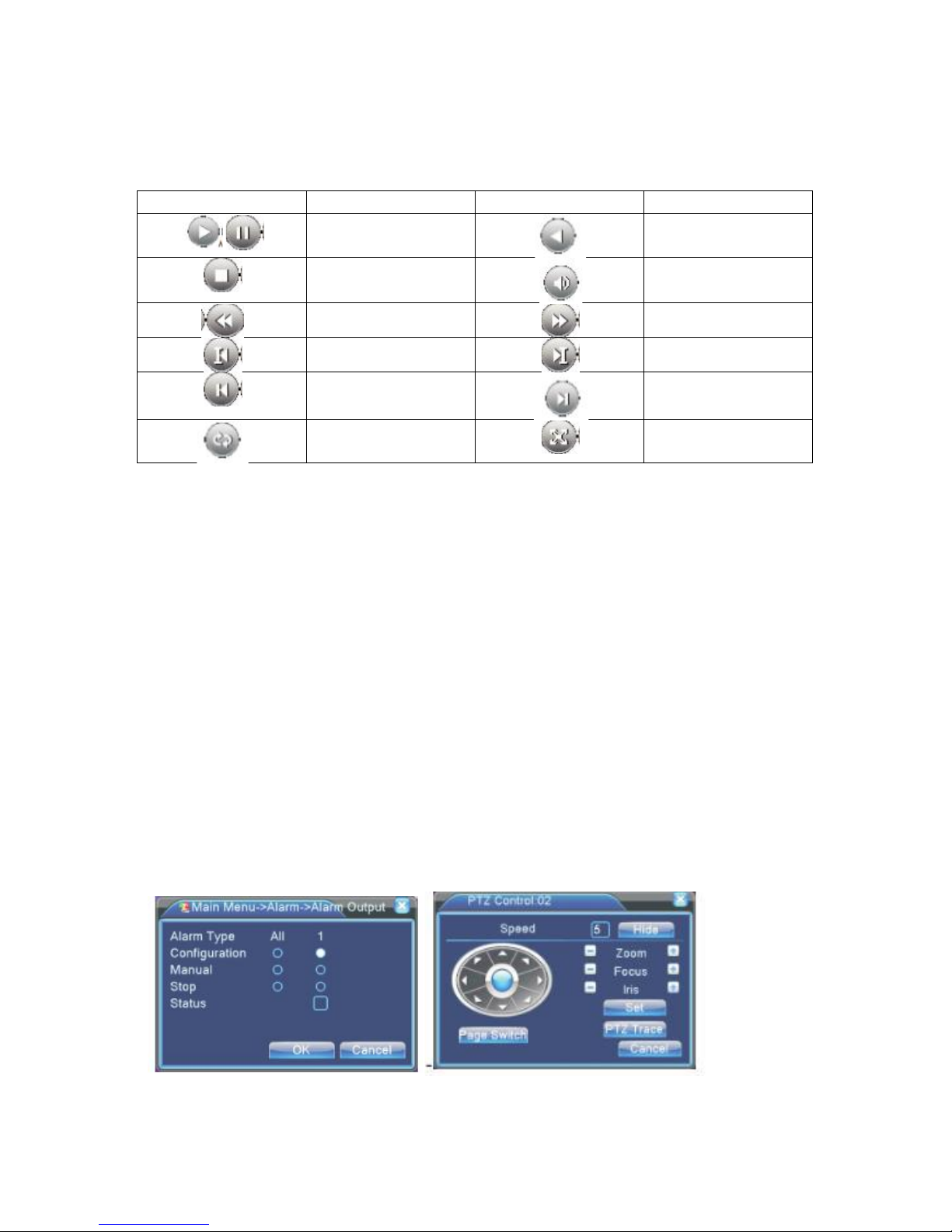
Button
Function
Button
Function
Stop
Volume
Slow play
Fast play
Previous frame
Next frame
Previous file
Next file
Repeat playback
Full screen
Channel: Set the searching channel.
Start Time: Set the searching time scan.
Playback control: Refer to the following sheet for more information.
Play/pause
Backward
Operation hint: Displays the function of the cursor place.
NOTE: Frame by frame playback is only performed in the pause playback mode Special
Functions: Accurate playback: Input time (H/M/S) in the time column and then click 'Play'.
The system can operate accurate playback according to the searching time.
Local zoom: When the system is in single-window full-screen playback mode, you can drag
your mouse in the screen to select a section and then left click mouse to realize local zoom.
You can right click mouse to exit.
3.5.3 Record Mode
Please check current channel status: “o” means it is not in recording status “●” means it is in
recording status. You can use desktop shortcut menu or click [main menu] > [recording set]
to enter the recording control interface.
[Schedule] Record according to the configuration.
[Manual] Click the 'All' button and the corresponding channel starts recording, no matter
the channel in any state.
[Stop] Click the 'Stop' button and the corresponding channel stops recording, no matter the
channel in any state.
3.5.4 Alarm output
Picture 3.8 Alarm output Picture 3.9 PTZ Setup
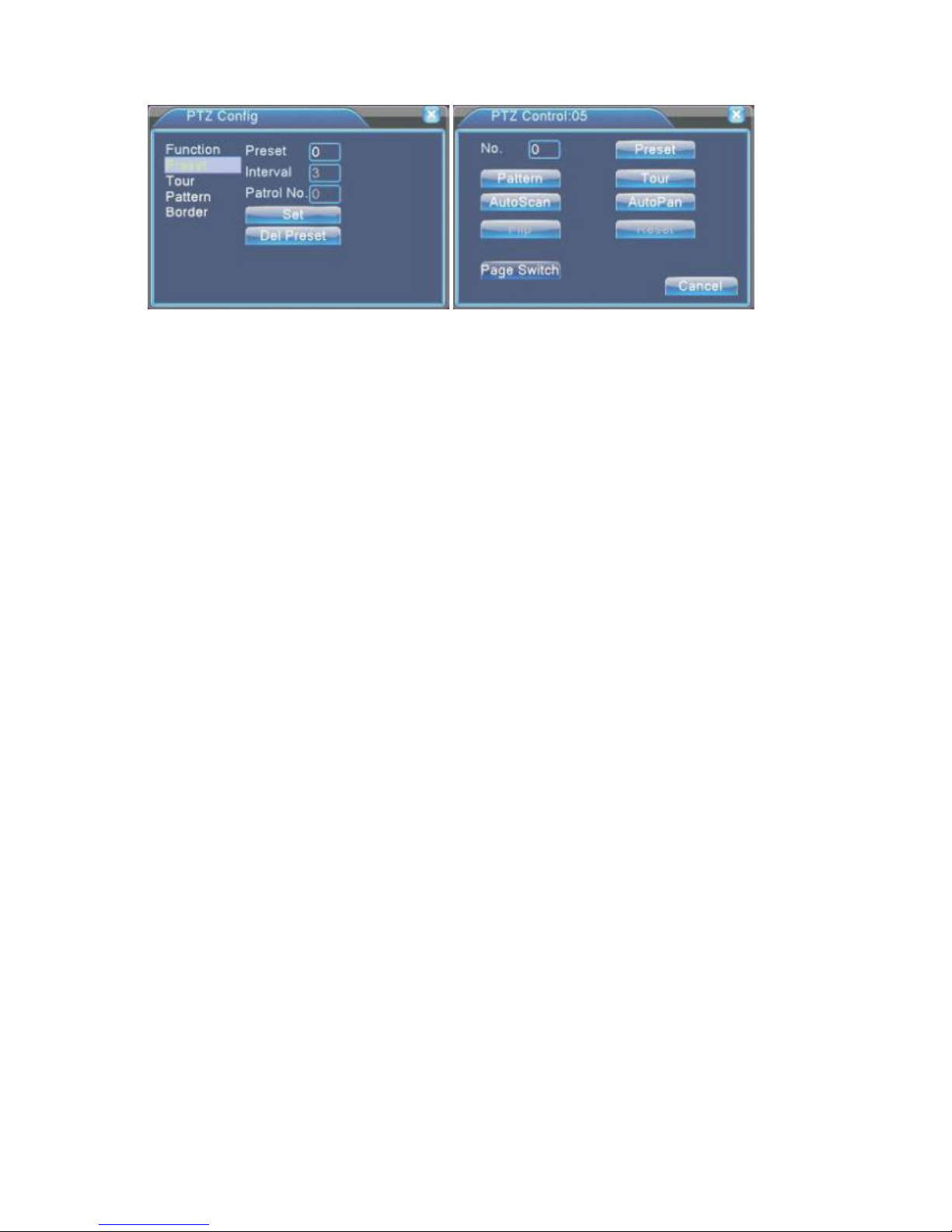
Picture 3.10 Preset Settings Picture 3.11 PTZ Control
3.5.5 PTZ control
Operation interface is as follows. The functions include: PTZ direction control step, zoom,
focus, iris, setup operation, tour between spots, trial tour, boundary scan, assistant switch,
light switch, level rotation and so on. Note
1. Decoder A(B) line connects with DVR A(B) line. The connection is right.
2. Click [main menu] > [system configuration] > [PTZ setup] to set the PTZ parameters.
3. The PTZ functions are decided by the PTZ protocols.
[Step] Set the PTZ rotation range, Default range 1-8.
[Zoom]click +/ - button to adjust the zoom multiple of the camera.
[Focus]click +/ - Button to adjust the focus of the camera.
[Iris] click +/ - Button to adjust the iris of the camera.
[Direction control] Control the PTZ rotation, 8 directions control is supportive, (4 directions
in front panel is supportive).
[High speed PTZ] Full screen shows channel image, left press mouse and control PTZ to
rotate, then rotate the mouse to adjust the zoom multiple of the camera.
[Setup] Enter the function operation menu.
[Window switch] Switch between different windows.
Special Function:
1. Preset. Set a location for the preset, calls the preset points, PTZ automatically turns to the
set position.
1) Preset option
Set a location for the preset, procedure is as follows:
Step 1:In picture 3.10, clicking the direction buttons will turn into preset position, click the
'set' button to enter Picture 3.11.
Step 2:Click the 'Preset' button, then write the preset points in the input box.
Step 3:Click 'Set' button, return to the picture 3.10. Complete setup that is the preset points
and preset position corresponds to the values entered.
DEL Preset: After entering preset points, click 'Del Preset' button to remove the preset.
2) Preset point calls
In picture 3.10, click 'Page switch' button, enter PTZ control interface as shown in picture
3.12. In the input blank, write the preset point number, then click 'Preset' button, PTZ turns
to the corresponding preset point.
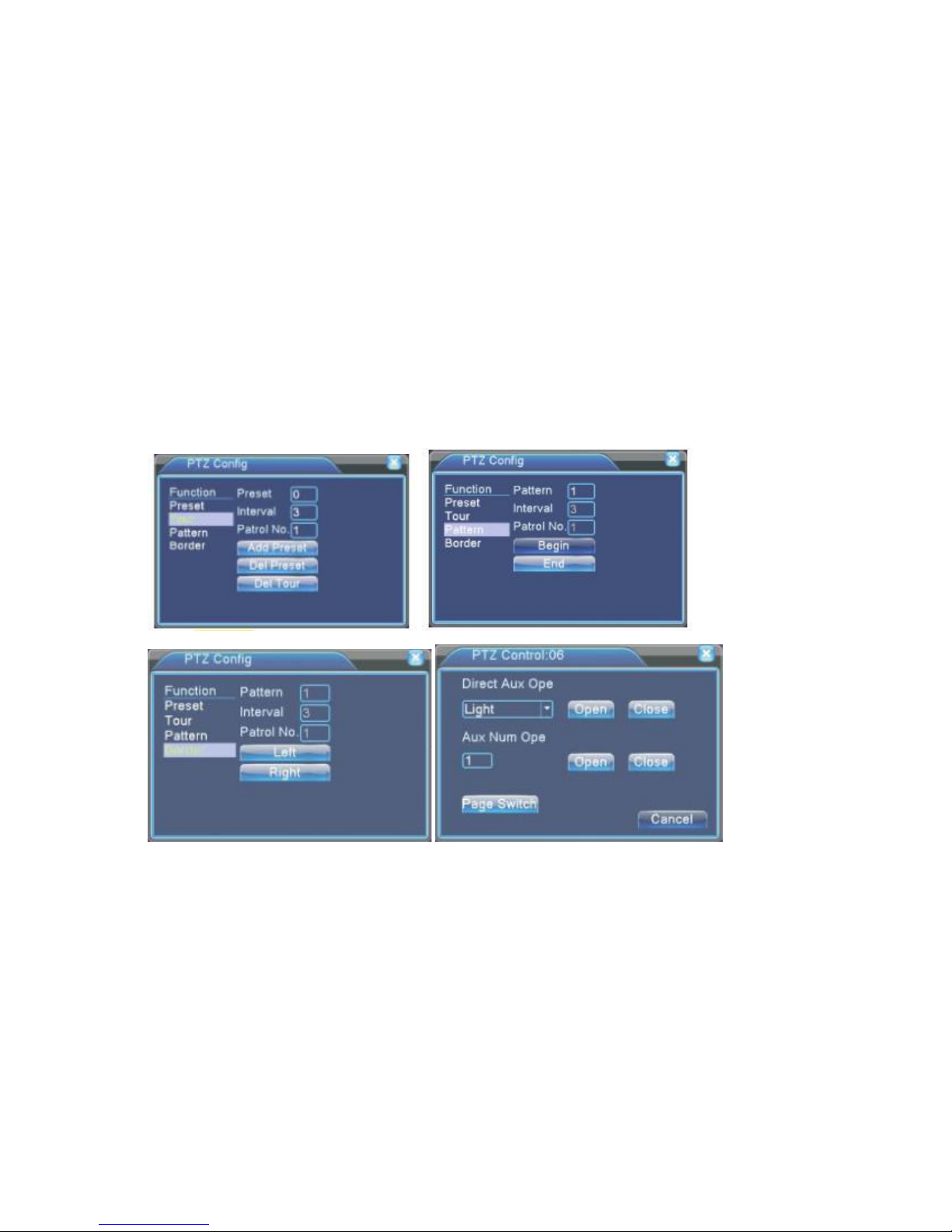
2. Tour between Points Multiple preset points connected tour line, call tour points, the PTZ
run around on the line.
1) Tour between points settings
Tour line is connected by multiple preset points, setting procedure is as follows:
Step 1: In picture 3.10, the Direction key will turn PTZ to designated location, click 'Set'
button to enter Picture 3.13.
Step 2: Click 'Tour' button, then write proper values in the 'Preset' box, then click 'Add
preset' button and complete settings (also can add or delete tour which has been set up).
Step 3: Repeat step 1 and step 2, until all the points in the preset designated tour is set.
Del Preset: Please input preset value in the box, click 'Del Preset' button to remove the
preset points.
Del Tour: Input the number of tour line, click 'Del Tour' button to remove the tour lines set.
2) The Calls of Tour between Points.
In picture 3.10, click 'Page Switch' button, enter PTZ control menu as shown in picture 3.12.
Please input the number of tour in the box, then click 'Tour' & PTZ begins to work on the
tour line.
Picture 3.12 Tour between point settings Picture 3.13 Scan Setup Picture
Picture 3.14 Boundary Scan Setup Picture 3.15 Auxiliary Function
3. Pattern PTZ also can work on the preset scan line repeatedly.
1) Pattern setup
Step 1: In picture 3.10, click 'Set' button, enter picture 3.14.
Step 2: Click Pattern button, then enter proper values in the scan box.
Step 3: Click Begin button, enter picture 3.10, here you can set the following terms: Zoom,
Focus, Iris, Direction and soon click 'Set' button to go back picture 3.14.
Step 4: Click 'End' button to complete setup. Click right button of the mouse to exit.
2) Pattern Calls
 Loading...