

Page 1
深圳市神牛摄影器材有限公司
GODOX Photo Equipment Co., Ltd.
地址/Add: 深圳市宝安区福永镇福洲大道西新和村华发工业园A4栋
Building A4, Xinhe Huafa Industrial Zone, Fuzhou RD West, Fuyong
Town, Baoan District, Shenzhen 518103, China
电话/Tel: +86-755-29609320(8062) 传真/Fax: +86-755-25723423
邮箱/E-mail: godox@godox.com
705-X1C000-00
Made In China
TTL
无线引闪器
TTL Wireless Flash Trigger
For Canon
Instruction Manual
说 明 手 册
Chinese English Bilingual
中英文双语
Page 2

规格参数
可控从属单元组
传输范围(约)
频道
其他
时延设置
无线快门
ZOOM设置
显示屏
输出接口
固件更新
记忆功能
发射器尺寸/净重
接收器尺寸/净重
GR 分组模式下,最多5组(A/B/C/D/E)
Ratio光比分组模式下,3组(A/B/C)
>100米
32个
有(0~10ms,以100us为单位设置)
接收器端可以通过2.5mm同步接口控制相机拍摄
可以通过发射器调节闪灯焦距值
宽屏液晶显示,背光开启或关闭
发射器:PC 端子输入、输出;接收器:2.5mm同步线输出
通过机身上的 Micro USB进行固件升级
设置2秒后的参数会自动记忆,重新开机自动恢复
72x75x52(mm)/100g
70x65x47(mm)/70g
兼容相机
Canon EOS 数码单反相机, 包括:
1Dx Mark II, 1Dx, 5Ds/5Dsr, 5D Mark IV, 5D Mark III, 5D Mark II, 5D, 7D Mark II, 6D, 7D,
80D, 77D, 70D, 60D, 50D, 40D, 30D, 750D/760D, 100D, 800D, 700D, 650D, 600D, 550D,
500D,450D, 400D DIGITAL(EOS Kiss Digital X), 350D DIGITAL, 1300D(Rebel T6),1200D,
1100D, 1000D, M6, M5, M3,
- 23 - - 24 -
Contents
Foreword
25
Warning
26
Names of Parts
28
Body
LCD Panel
Accessories
Battery
30
Installing Batteries
Low Battery Level Indication
Using the Flash Trigger
31
As a Wireless Studio Flash Trigger
As a Wireless Speedlite Trigger
As a Wired Shutter Release
As a Wireless Studio Flash Trigger
or Speedlite
Trigger with PC Sync Socket
Setting the Transmitter
33
Power Switch
Power Switch of AF Assist Beam
Channel Settings
Mode Settings
Current Group Settings
Multi Flash Settings (Times & Frequency)
Multi Flash Settings (Output Value)
Group Settings
Test Flash
Modeling Lamp Control
Setting GR Grouping Mode
Automatically Enter Power Saving Mode
C.Fn: Setting Custom Functions
Wireless Shutter Release Mode
Setting the Camera
Setting the Receiver
41
Channel Settings
Group Settings
Automatically Enter Power Saving Mode
Selecting the Operation Method
43
Attentions
47
Caring for Flash Trigger
48
Technical Data
49
Page 3

Foreword
Warning
Thanks for your purchase of this X1C TTL wireless flash trigger.
This TTL wireless flash trigger can be used with a transmitter and one or more receivers for
studio flash, speedlite, and camera shutter. Featuring multi-channel triggering, stable signal
transmission, and sensitive reaction, it gives photographers unparalleled flexibility and
control over their strobist setups. The flash trigger applies to hotshoe-mounted Canon EOS
series cameras, as well as the cameras which have PC sync sockets.
With X1C wireless flash trigger, high speed synchronization is available for most of camera
flashes in the market which support E-TTL II. The max flash synchronization speed is up to
1/8000s *.
*: 1/8000s is achievable when the camera has a max camera shutter speed of 1/8000s. 1/8000s is not
achievable because some models of Canon EOS cameras have a max camera shutter speed of only 1/4000s.
- 25 - - 26 -
Do not disassemble. Should repairs become necessary, this product must be
sent to an authorized maintenance center.
Always keep this product dry. Do not use in rain or in damp conditions.
Keep out of reach of children.
Do not use the flash unit in the presence of flammable gas. In certain
circumstance, please pay attention to the relevant warnings.
Do not leave or store the product if the ambient temperature reads over 50℃.
Turn off the flash trigger immediately in the event of malfunction.
Observe precautions when handling batteries
Use only batteries listed in this manual. Do not use old and new batteries or
batteries of different types at the same time.
Read and follow all warnings and instructions provided by the manufacturer.
Batteries cannot be short-circuited or disassembled.
Do not put batteries into a fire or apply direct heat to them.
Do not attempt to insert batteries upside down or backwards.
Batteries are prone to leakage when fully discharged. To avoid damage to the
product, be sure to remove batteries when the product is not used for a long
time or when batteries run out of charge.
Should liquid from the batteries come into contact with skin or clothing, rinse
immediately with fresh water.
Page 4
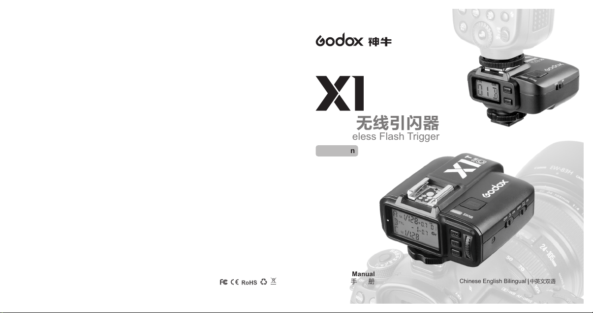
Names of Parts
Names of Parts
Body
Transmitter
Battery
Compartment
Micro USB Port
PC Sync Socket
Hot Shoe Speedlite
Connection
LCD Panel
Hot Shoe Camera
Connection
Receiver
TEST Trigger Button
--Half Press
--Fully Press
AF Assist Beam Switch
--ON(AF Assist Beam outputs)
--OFF(AF Assist Beam do
not output)
Power Switch
--ON (Power On)
--OFF (Power Off)
Status Indicator Lamp
--LED Red Color Lamp
CH/OK Channel
Setting Button
GR Group Setting
Button
Select Dial
MODE Mode Selection
Button
- 27 - - 28 -
Hot Shoe Speedlite
Battery
Compartment
Micro USB Port
2.5mm Shutter
Release Port
Connection
LCD Panel
TEST Trigger Button
Power Switch
--ON (Power On)
--OFF (Power Off)
Status Indicator Lamp
--LED Red Color Lamp
CH Channel Setting Button
GR Group Setting Button
Page 5
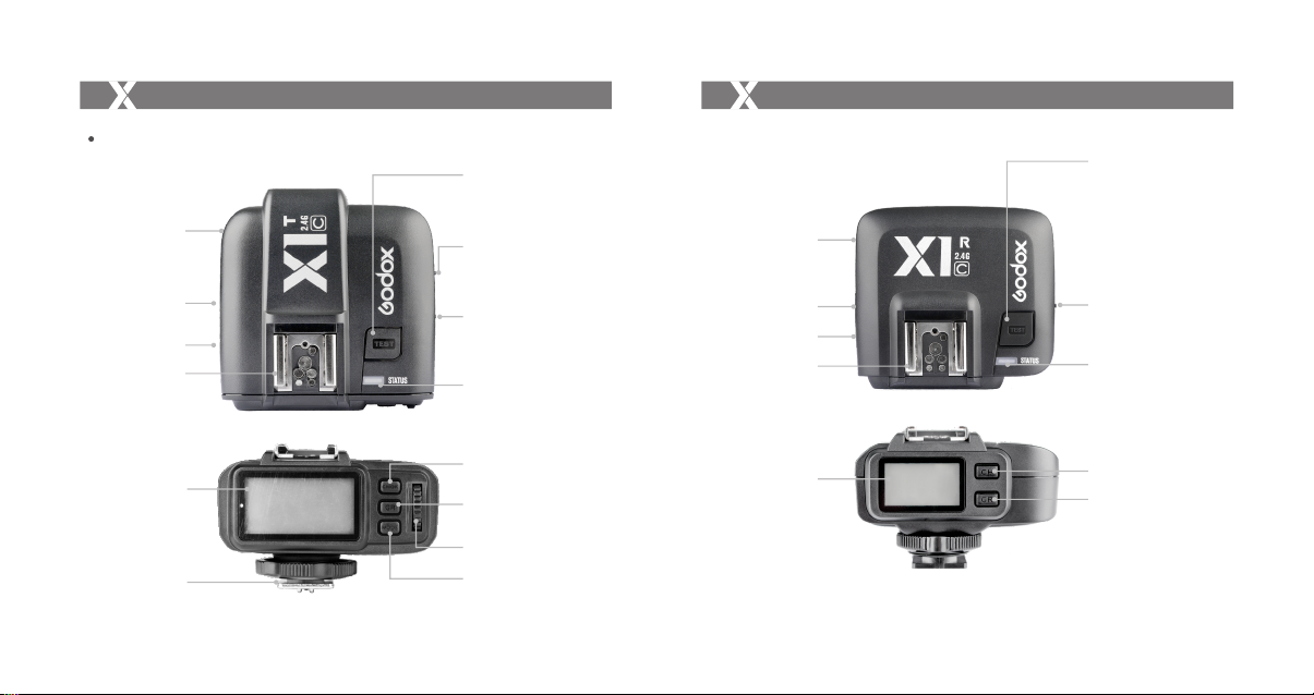
Names of Parts
Names of Parts
Transmitter Panel
CH
D
C
(A) Output Settings per Group in the M Mode; FEC Settings per Group in the TTL Mode
(B) Mode Settings (C) Group (D) Currently Selected Group (E) Channel Settings
(F) Low Battery Warning (G) GR Grouping Icon (H) Synchronization Delay Setting Icon
(I) Multi Mode Icon (J) Single Contact Icon (K) Second Curtain Sync
Gr
AB
E
F
G
H
I
J
K
Receiver Panel
GRCH
B
(A) Group Setting (B) Channel Setting (C) Low Battery Indicator
A
- 29 - - 30 -
C
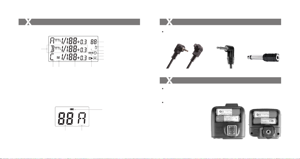
Accessories
1. Remote Cable(C1, C3) 2. Sync Cable 3.Sync Adapter
Battery
Installing Batteries
As shown in the illustration, slide the battery compartment lid of the transmitter and
receiver and insert two AA batteries (sold separately)separately.
Low Battery Indication
When the battery power (2 AA
batteries <2.0V) gets low,
Status Indicator Lamp blinks
quickly (blink cycle=0.5s).
Please replace new batteries,
as low power leads to no flash
or flash missing in case of
long distance.
Page 6

Using the Flash Trigger
Using the Flash Trigger
The flash trigger features the following functions:
1. As a Wireless Studio Flash Trigger
1.1 Mount the transmitter on camera hotshoe and turn it
on before turning on the camera.
1.2 Connect the receiver to studio flash by Sync Cable
(one end in 2.5mm Shutter Release Port of the
receiver, the other end in sync port of studio flash)
before turning on the studio flash.
1.3 Set the transmitter and the receiver to the same
channel.
1.4 Press the camera shutter button, and the studio
flash will be triggered simultaneously. Status
Indicator Lamp of both transmitter and receiver
units turn red.
2. As a Wireless Speedlite Trigger
2.1 Mount the transmitter on camera hotshoe and turn it
on before turning on the camera.
2.2 Mount the speedlite to Hot Shoe Speedlite
Connection of receiver unit. Set the speedlite to M
mode.
2.3 Set the transmitter and the receiver units to the
same channel.
2.4 Press the camera shutter button, and the speedlite
will be triggered simultaneously. Status Indicator
Lamp of both transmitter and receiver units turn red.
- 31 - - 32 -
3. As a Wired Shutter Release
3.1 Connect the receiver and the camera by Remote
Cable (one end in receiver’s Shutter Release
Port, the other end in camera’s shutter port)
before turning on the camera.
3.2 Half press the <TEST> Trigger Button to focus.
When fully press the <TEST> Trigger Button to
shoot, the Status Indicator Lamp will turn red until
releasing the button.
4. As a Wireless Studio Flash Trigger or Speedlite
Trigger with PC Sync Socket
4.1 The connection method of the receiver can be
found in As a Wireless Studio Flash Trigger and As
a Wireless Speedlite Trigger section.
4.2 The transmitter will control the flash on the
receiver end to fire via using PC Sync Socket as
input by default.
4.3 Press the camera shutter and use the PC Sync
Socket’s signal to control the flash.
4.4 PC Sync Socket can also be set as output. Long
press the <CH/OK> Button of the transmitter until
<Fn> is displayed on the panel. Then, set the
value of C.Fn-03 to ou, and the PC Sync Socket is
under output mode.
Page 7

Setting the Transmitter
Setting the Transmitter
Power Switch
Slide the Power Switch to ON, and the device is on and Status Indicator Lamp will not blink.
Note: In order to avoid power consumption, turn off the transmitter when not in use.
Power Switch of AF Assist Beam
Slide the power switch to ON, and the AF lighting is allowed to output.
Channel Setting
1. Short press the <CH/OK> Button until the
channel amount blinks.
2. Turn the Select Dial to choose the
appropriate channel. Press the <CH/OK>
Button again to confirm the setting.
3. This flash trigger contains 32 channels
which can be changed from 1 to 32. Set the
transmitter and the receiver to the same
channel before usage.
- 33 - - 34 -
CH
Gr
Mode Setting
1. Short press the <MODE> Button, and the
mode of the current group will change.
2. To NON-GR grouping mode, all the groups’
modes will be changed simultaneously by
CH
Gr
the order of TTL/M/Multi, in accordance
with Ratio flash mode. To GR grouping
mode, only the current group’s mode will
be changed by the order of TTL/M/--.
Current Group Settings
1. Short press the <GR> Button to set the
current group.
2. The current group settings will blink and
turn the Select Dial to change the settings.
3. When the current group is in the M mode,
the power output value is changeable from
1/1 full power to Min.[Note 1] power in 0.3
stop increments. When the current group
is in the TTL mode, the FEC amount is changeable
from -3 to 3 in 0.3 stop increments. When the current group is in the -- mode (flash
off), the amounts will not change.
4. Short press the <GR> Button again to confirm the setting.
[Note 1]
Min. refers to the minimum power output value that can be set in M/Multi mode.
X1C's minimum power output value is 1/128 for most of camera flashes. However, the value can
change to 1/256 when using in combination with Godox strong power flashes e.g. AD600, etc.
CH
Gr
Page 8

Setting the Transmitter
Setting the Transmitter
Multi Flash Settings (Times & Frequency)
1. In the multi flash (TTL and M icon are not
displayed), long press the <MODE> Button to
enter multi flash setting submenu.
2. The two lines are separately displayed as T
(flash times) and H (flash frequency).
3. Short press the <GR> Button to choose the
related setting amounts. Turn the Select Dial
to change the blinking settings.
4. Continue to short press the <GR> Button, and the blinking settings on the next line can
be changed.
5. Until all the amounts are set. Short press the <MODE> Button to exit the setting status.
6. In the multi flash setting submenu, short press the <MODE> Button to return to main
menu.
Multi Flash Settings (Output Value)
1. In the multi flash (TTL and M icon are not
displayed), short press the <GR> Button to
set the current group.
2. In multi flash mode, the power output will be
changed from Min. to 1/4.
Note: As flash times are restricted by flash output value and flash frequency, the flash times
cannot surpass the upper value that permitted by the system.
The times that transported to the receiver end are a real flash time, which is also related to the
camera's shutter setting.
- 35 - - 36 -
CH
Group Settings
1. Long press the <GR> Button to set all effective groups simultaneously.
2. The settings of all effective groups will blink. Turn the Select Dial to change the
settings, until one of the group's setting turns to the maximum or the minimum and all
settings of the effective groups will not change now.
3. If the current group is in the M mode, the power output value is changeable from 1/1
full power to Min. power in 0.3 stop increments, until one of the group’s setting turns to
the maximum(1/1) or the minimum(Min.). If the current group is in the TTL mode, all
the other groups which are in the M mode will change their FEC amount
simultaneously. The FEC amount is changeable from -3 to 3 in 0.3 stop increments,
until one of the group’s setting turns to the maximum(3) or the minimum(-3). If the
current group is in the -- mode (flash off), the amounts will not change.
4. If the groups in the M mode or TTL mode work together, the first FEC amount which
up to the maximum or the minimum is considered as the limitation.
5. Short press the <GR> Button again to confirm the setting.
Page 9

Setting the Transmitter
Setting the Transmitter
Test Flash
1. Press the <TEST> Trigger Button to see the
whether flash will fire normally or not.
2. Fully press the <TEST> Trigger Button, and
the Status Indicator Lamp turns red and the
flash on the receive end can be triggered.
3. Use the transmitter to control camera to
focus or shoot, and the transmitter is
connecting to the camera (do not connect to
the flash) now.
4. In the standby mode, press the TEST
Button can wake up the receiver.
5. The settings on the transmitter end will synchronize to the receiver end at the same
time.
Modeling Lamp Control
Double-click the <CH/OK> Button to power ON/OFF the modeling lamp.
Setting GR Grouping Mode
1. Press the <MODE> Mode Button until Gr
icon is displayed, which shows that GR
grouping mode has been set.
2. To cancel GR grouping mode, press the
<MODE> Button again until the Gr icon
disappeared.
Note: GR mode can only be used normally when attaching to the CANON EOS cameras that
issued after 2012. In the GR mode, multi flash cannot be set.
CH
Gr
Automatically Enter Power Saving Mode
1. The flash trigger will go into standby mode after the transmitter enter sleep mode, and
the displays on the LCD panel will disappear.
2. Press any of the button (<TEST> fully pressed/<CH/OK>/<GR>/<MODE>) can wake
up the flash trigger. If the transmitter is attached to the CANON EOS camera, half
press the shutter can also wake up the system.
3. If the transmitter is set to single contact mode( isdisplayed), the system will not
enter power saving mode.
C.Fn: Setting Custom Functions
The following table lists the available and unavailable custom functions of this flash. The
icon“√”indicates the flash custom function is supported but “0”indicates the custom
function is not supported.
Custom
Functions No.
C.Fn-00
C.Fn-01
Functions
Synchronization
delay setting
Single contact
mode
Setting Signs
1~100
Settings and Description
No delay
00
Synchronization delay N*100 us
(synchronization delay icon is displayed.)
--
OFF
on
ON(The single contact mode set icon
is displayed.)
- 38 -- 37 -
Application
√
√
Page 10

Setting the Transmitter
Setting the Transmitter
Custom
Functions No.
C.Fn-01
C.Fn-02
C.Fn-03
C.Fn-04
C.Fn-05
C.Fn-06
C.Fn-07
Functions
Single contact
mode
Zoom setting
PC sync socket
as an input/
output
Second curtain
sync [Note 2]
Minimum power
output value in
M/Multi mode
Displayed
groups
Beeper ON/OFF
Setting Signs
on
--
AU
20,24,28,35,50,70,
80,105,135,200
In
ou
--
on
1/128
1/256
03
05
--
on
Settings and Description
It is advisable to set the transmitter to single
contact mode when using it to trigger the flash
by PC cord or through camera’s single contact.
OFF
Changing with camera's zoom value.
Zoom(20/24/28/35/50/70/80/105/135/
200mm)
PC sync socket connects with camera as an input
PC sync socket connects with flash as an output
Second curtain sync off
Second curtain sync on
1/128
1/256
3 groups are displayed
5 groups are displayed
Turn off the beeper on the receive end
Turn on the beeper on the receive end
- 39 - - 40 -
Application
√
√
√
√
√
√
√
Functions No.
C.Fn-08
C.Fn-09
Double-click the CH Button to turn on/off the modeling lamp of the receive end.
Press the TEST Button to turn on the flash trigger. When the Status Indicator Lamp blinks two
times, it means the effective remote distance is below 30 meters, thus the transmitter and receiver
can communicate normally no matter how near they are.
[Note 2]:
Second curtain sync cannot be set through the camera's external flash functions setting.
When using second curtain sync, the effective shutter speed range is from 1/30s to 30s. When shutter speed
is set as buLb or is quicker than 1/30s, the settings are invalid.
After being turned on, second curtain sync is effective even though HSS has been set and the shutter speed
range is from 30s to 1/30s.
After second curtain sync is turned on, synchronization delay settings are invalid.
1. Press the <CH/OK> Button for 2 seconds or longer until <Fn> is displayed.
2. Select the custom function No.
3. Change the Setting.
FunctionsCustom
Send the setting
value forcibly
APP mode
* Turn the Select Dial to choose the Custom Function No.
* Press the <GR> Button until the custom function No. blinks.
* Turn the Select Dial to set the desired number. Pressing <GR> button will confirm the settings.
* Press <MODE> button to exit the C.Fn settings.
Setting Signs
Settings and Description
Only send after the setting values have been
--
changed.
Forcibly send the setting values before firing
on
even though the values has not been changed.
The transmitter is in the master mode, which
can set the receiver’s mode and output on the
--
transmitter end.
Open the APP mode and the transmitter can
on
only trigger flashes. Only channel and custom
settings can be adjusted and the LCD panel
will display APP.
Application
√
√
√
√
Page 11

Setting the Transmitter
Setting the Receiver
Wireless Shutter Release Mode
Half press the <TEST> Trigger Button to focus. Fully press the <TEST> Trigger Button,
and the Status Indicator Lamp turns red. Now camera is ready to shoot. When releasing
the button, the Status Indicator Lamp turns off.
Setting the Camera
Use the External Flash Function on the camera to do the setting.
Note: 1. GR mode can only be used normally when attaching to the CANON EOS cameras that
issued after 2012. If the camera model do not support GR grouping flash mode,
NON GR mode will be changed automatically.
2. In the NON-GR mode, Ration Off is steadily set in the TTL mode while A:B C is steadily set
in the M mode.
Setting the Receiver
Channel Setting
1. Short press the <CH> Button and the channel
amount will increase a step each time.
2. Long press the <CH> Button will enter quicker
adjustment mode. The channel amount will
increase fast in this mode.
3. Release the <CH> Button and the current
channel amount is confirmed.
- 41 - - 42 -
4. The channel amount will increase from 1 to 32. When the current channel is 32, press
the <CH> Button again and the channel 1 will be displayed on the panel.
Group Settings
1. Short press the <GR> Button and the group
amount will increase a step each time.
2. Long press the <GR> Button will enter quicker
adjustment mode. The group amount will
increase fast in this mode.
3. Release the <GR> Button and the current
group amount is confirmed.
4. The group amount will increase from A to E. When the current group is E, press the
<GR> Button again and the group A will be displayed on the panel.
Note: If the transmitter in the same channel is set to NON-GR grouping mode, the effective groups
of the receiver will change from A to C. Make sure the receiver 's group is set to A/B/C.
If the transmitter in the same channel is set to GR grouping mode, the effective groups of the
receiver will change from A to E.
Automatically Enter Power Saving Mode
1. The system will go into standby mode after the transmitter goes into standby mode.
And the displays on the LCD panel disappear now.
2. To wake up the system, press the <TEST> Button or the <GR> Button. Fully press the
<TEST> Trigger Button of the transmitter can also wake up the receiver’s system. If
the transmitter is attached to the CANON EOS camera, half press the camera shutter
can also wake up the system.
Page 12

Selecting the Operation Method
Selecting the Operation Method
Transmitter:
Button
Operation
Short press
CH/OK
Double-click
Long press for
2 seconds
Long press for
5 seconds
GR
Short press
Long press for
2 seconds
MODE
Short press
Status
Select
Normal
Dial
Set the channel
Set the group
X1C Operation Method 1(by default)
TTL/M Mode (In the GR Mode or NON-GR Mode)
Function
(under normal status)Enter CH settings; (under settings)Confirm and back to
normal status
Control the ON/OFF of modeling flash
Enter C.Fn custom settings
Switch the Operation Methods (Method 1/Method 2)
Select the POWER/FEC settings
Select all the group
(under normal status) Switch the < Group> mode (TTL/M/OFF in the GR mode;
TTL/M/Multi in the NON-GR mode)
Function
Set the < Group>
Adjust the channel amount
Adjust the group’s POWER/FEC amount
- 43 -
Button
CH/OK
GR
MODE
Select
Dial
Operation
Short press
Double-click
Long press for
2 seconds
Long press for
5 seconds
Short press
Short press
Long press for
2 seconds
Status
Normal
Set the channel
Set the Group
Set the flash
times
Set the flash
frequency
Multi Mode (In the NON-GR Mode)
Function
(under normal status) Enter CH settings; (under settings) Confirm and back
to normal status
Control the ON/OFF of modeling flash
Enter C.Fn custom settings
Switch the Operation Methods (Method 1/Method 2)
(under PTH status) Set times /frequency hz
(under normal status) Switch the < Group> mode (TTL/M/Multi)
(under PTH status) Back to normal status
Enter PTH status (T-times, and H-hz)
Function
No (3 groups) /Turning (5 groups) [Note 3]
Adjust the channel amount
Adjust the group’s power amount
Adjust the times amount
Adjust the frequency amount
- 44 -
Page 13

Selecting the Operation Method
Selecting the Operation Method
Button
CH/OK
GR
MODE
Select
Dial
Operation
Short press
Double-click
Long press for
2 seconds
Long press for
5 seconds
Short press
Double-click
Long press for
2 seconds
Short press
Status
Normal
Set the channel
Set the group
X1C Operation Method 2
TTL/M Mode
Function
(under normal status) Enter CH settings; (under settings) Confirm and back
to normal status
Control the ON/OFF of modeling flash
Enter C.Fn custom settings
Switch the Operation Methods (Method 1/Method 2)
Select the group downwardly
Select the group upwardly
Select all the group
Switch the group’s flash mode(TTL/M/OFF)
Function
No (3 groups) / Turning (5 groups) [Note 3]
Set the channel amount
Adjust the group’s POWER/FEC amount
- 45 -
Button
CH/OK
GR
MODE
Select
Dial
Operation
Short press
Double-click
Long press for
2 seconds
Long press for
5 seconds
Short press
Double-click
Short press
Long press for
2 seconds
Status
Normal
Set the channel
Set the Group
Set the flash
times
Set the flash
frequency
Multi Mode (In the NON-GR Mode)
Function
(under normal status) Enter CH settings; (under settings) Confirm and back to
normal status
Control the ON/OFF of modeling flash
Enter C.Fn custom settings
Switch the Operation Methods (Method 1/Method 2)
Select the group downwardly (under PTH status) Set times /hz
Select the group upwardly
(under normal) Switch the < group>’s mode(TTL/M/Multi)
(under PTH status) Back to normal status
Enter PTH status(T- times, and H-hz)
Function
No (3 groups) /Turning (5 groups) [Note 3]
Adjust the channel amount
Adjust the group’s power amount
Adjust the times amount
Adjust the frequency amount
- 46 -
Page 14

Selecting the Operation Method
[Note 3] There are 5 groups only in the GR mode while 3 groups in other modes.
Choose 3 or 5 groups by setting C.Fn-06 to 03 or 05.
Receiver:
Button
CH
GR
Operation
Short press
Double-click
Short press
Double-click
Function
Select the channel amount upwardly
Select the channel amount downwardly
Select the group amount upwardly
Select the group amount downwardly
Attentions
1. Unable to trigger flash or camera shutter. Make sure batteries are installed correctly and
Power Switch is turned on. Check if the transmitter and the receiver are set to the same
channel, if the hotshoe mount or connection cable is well connected, or if the flash
triggers are set to the correct mode.
2. Camera shoots but does not focus. Check if the focus mode of the camera or lens is set
to MF. If so, set it to AF.
3. Signal disturbance or shooting interference. Change a different channel on the device.
4. Operating distance limited or flash missing. Check if batteries are exhausted. If so,
change them.
5. No or is displayed on the camera viewfinder, though the camera is mounted on
the transmitter and the power switch is turned on. This is resulted from unusual working
of the transmitter. Check and make sure the flash trigger is well connected to the camera
through Hot Shoe Camera Connection, then power the Transmitter on again.
H
- 47 -
Caring for Flash Trigger
Avoid sudden drops. The device may fail to work after strong shocks, impacts, or
excess stress.
Keep dry. The product isn't water-proof. Malfunction, rust, and corrosion may occur and
go beyond repair if soaked in water or exposed to high humidity.
Avoid sudden temperature changes. Condensation happens if sudden temperature
changes such as the circumstance when taking the transceiver out of a building with
higher temperature to outside in winter. Please put the transceiver in a handbag or
plastic bag beforehand.
Keep away from strong magnetic field. The strong static or magnetic field produced
by devices such as radio transmitters leads to malfunction.
- 48 -
Page 15

Technical Data
Technical Data
Model
Type
Compatible Cameras
Builted-in remote system
Modulation mode
Power supply
Exposure Control
Manual flash
TTL autoflash
TTL Control
High-speed sync
Flash exposure compensation
Flash exposure lock
Focus assist
Multi flash
Second curtain sync
Modeling flash
Wireless Flash
Wireless function
Controllable slave group
X1C
For Canon
Canon EOS cameras (E-TTL II autoflash)
Support for the cameras that have PC sync socket.
2.4G Wireless Transmission
MSK
2*AA batteries
Yes
E-TTL II
Yes
Yes, ±3 stops in 1/3 stop increments
Yes
Manual open
Yes
Yes
Yes, fired with camera's depth-of-field preview button
In TTL mode, Ratio Off
In M mode, Flash Ratio (A:B C)
Support for GR group flash, A~E group can set their flash mode separately.
In the GR grouping mode, 5 (A/B/C/D/E)
In the Ratio grouping mode, 3 (A/B/C)
- 49 - - 50 -
Model
Type
Transmission range(approx.)
Channel
Others
Synchronization delay set
Wireless shutter release
ZOOM setting
LCD panel
Output interface
Firmware upgrade
Memory function
Dimension/Weight for Transmitter
Dimension/Weight for Receiver
X1C
For Canon
>100m
32
Yes (0~10ms, use 100us as the unit)
Receiver can control camera shooting through 2.5mm sync port
Adjust the flash's focal length through the transmitter
Wide LCD panel, backlight on/off
Transmitter: use a PC cord to input and output
Receiver: use a 2.5mm sync cord to output
Use the Micro USB port to upgrade
Settings will be stored 2 seconds after last operation and
recover after a restart
72x75x52(mm)/100g
70x65x47(mm)/70g
Compatible Camera Models
Canon EOS SLR Digital Cameras:
1Dx Mark II, 1Dx, 5Ds/5Dsr, 5D Mark IV, 5D Mark III, 5D Mark II, 5D, 7D Mark II, 6D, 7D,
80D, 77D, 70D, 60D, 50D, 40D, 30D, 750D/760D, 100D, 800D, 700D, 650D, 600D, 550D,
500D,450D, 400D DIGITAL(EOS Kiss Digital X), 350D DIGITAL, 1300D(Rebel T6),1200D,
1100D, 1000D, M6, M5, M3,
 Loading...