

Page 1

TTL Li-ion Camera Flash
For Canon
82.AV860C00-00 VA
INSTRUCTION MANUAL
说 明 手 册
中英文双语 / Chinese English Bilingual
Before using this product
Please read this user manual carefully in order to ensure your safety
and the proper operation of this product. Keep for future reference.
Page 2

Foreword
For Your Safety
Thank you for purchasing this product.
series is a Godox original product and the world’s first Li-ion
powered camera flash, pioneering innovation in the industry. The
LiPo battery obviously enhances recycle, runtime, mobility, and
portability performance. This model applies to Canon EOS series
cameras and is compatible with E-TTL II autoflash. With this
E-TTL II compatible flash, your shooting will become simpler. You
can easily achieve a correct flash exposure even in complex light-
changing environments. This camera flash features:
●
GN58 (m ISO 100, @105mm). Adjust from 1/1 to 1/128 in 1/3rd
stops
●
Support Canon E-TTL II autoflash, Manual and Multi flash modes
●
Workable as Master and Slave unit in a wireless flash group
●
Pro 2000 mAh Li-ion Battery―max. 1.5s recycle―650 full power
pops
●
Super value and no messing with AA’s, external power pack, or
chargers
●
Use optional FT-16S to adjust flash parameters & trigger the flash
●
Stable consistency and color temperature with good even lighting
●
User-friendly LCD display & control panel with firmware upgrade
Always keep this product dry. Do not use in rain or in damp
conditions.
This product contains high-voltage electronic parts. Touching
the high-voltage circuit inside it may result in electric shock. Do
not disassemble. Should repairs become necessary, this
product must be sent to an authorized maintenance center.
Stop using this product if it breaks open due to extrusion, falling
or strong hit. Otherwise, electric shock may occur if you touch
the electronic parts inside it.
Do not fire the flash directly into the eyes (especially those of
babies) within short distances. Otherwise visual impairment
may occur. When taking pictures for babies, keep the flash unit
at least 1 meter (3.3 feet) away from them. Using bounce flash
to reduce light intensity is also recommended.
Do not use the flash unit in the presence of flammable gases,
chemicals and other similar materials. In certain circumstances,
these materials may be sensitive to the strong light emitting
from this flash unit and fire or electromagnetic interference may
result.
Do not leave or store the flash unit in places where the ambient
temperature reads over 50°C (e.g. in automobile). Otherwise
the electronic parts may be damaged.
- 01 - - 02 -
Page 3

Pioneering Li-ion Camera Flash
Conventions used in this Manual
This manual is based on the assumption that both the camera
●
and camera flash’s power switches are powered on.
● Reference page numbers are indicated by “p.**”.
● The following alert symbols are used in this manual:
The symbol gives supplemental information.
Caution
The symbol indicates a warning to prevent shooting
Note
problem.
Contents
Foreword
01
For Your Safety
02
Name of Parts
05
Body
Control Panel
LCD Panel
What’s in the Box of V860C Kit?
What’s in the Box of V860C (only flash unit)?
Separately Sold Accessories
Battery
08
Features
Cautions
Loading and Unloading the Battery
Battery Level Indication
Attaching to a Camera
09
Power Management
09
Flash Mode— E-TTL Autoflash
09
FEC (Flash Exposure Compensation)
FEB (Flash Exposure Bracketing)
FEL: Flash Exposure Lock
High-Speed Sync
Second-Curtain Sync
Flash Mode—M: Manual Flash
12
Flash Mode—Multi/Stroboscopic Flash
13
Wireless Flash
14
Wireless Settings
Fully Automatic Wireless Flash
Master Unit’s Flash OFF
Setting the Communication Channel
Setting the Flash Output for Slave Units
Other Applications
19
Wireless Control Function
Sync Triggering
Modeling Flash
Auto Focus Assist Beam
Bounce Flash
Creating a Catchlight
ZOOM: Setting the Flash Coverage and Using the Wide Panel
C.Fn: Setting Custom Functions
22
Control with the Camera’s Menu Screen
23
Protection Function
24
Technical Data
25
Troubleshooting
26
Firmware Upgrade
27
Compatible Camera Models
27
Maintenance
27
- 03 - - 04 -
Page 4
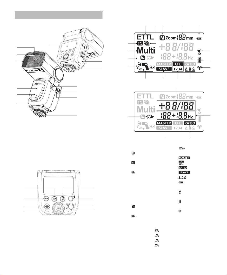
Name of Parts
● LCD Panel
01 05 02 03 18
01
02
03
04
05
13
09
07
12
06
08
● Body
01. Catchlight Panel 08. Hotshoe
02. Built-in Wide Panel 09. LCD Panel
03. Flash Head 10. Lock Ring
04. Optic Control Sensor 11. Li-ion Battery Compartment
05. Focus Assist Beam 12. USB Port
06. Wireless Control Port 13. Slave Flash Ready
07. Sync Cord Jack Indicator
15
14
17
18
16
21
20
19
● Control Panel
14. Mode Selection Button 17. LCD Panel Illumination /
15. Zoom Button / Wireless Custom Function Button
Selection Button 18. Select Dial
16. HSS (FP flash) / Shutter 19. Set Button
Curtain Synchronization 20. Power Switch
Button 21. Test Button / Flash Ready
Indicator
04
06
11
10
09
11
12 16 14 17
07
10
13 15
01. < ETTL > ETTL Autoflash 12. < > S1/S2 Optic Slave
02. < > Manual Zoom Flash
03. Zoom Focal Length 13. < > Master
04. < > Flash Exposure 14. < >Channel
Compensation 15. < > Flash Ratio
05. < > Flash Exposure 16. < > Slave
Bracketing 17. < > Slave ID
06. <M/Multi> Manual Flash / 18. < > Battery Level
Multi Flash Indication
07. Manual Flash Output Level 19. < > Max. Output
08. Multi Flash Times / Indication
Frequency 20. < > Overtemperature
09. < > High-Speed Sync Indication
(FP flash) 21. < > Wireless Signal
10. < > Second-Curtain Transmission
Sync
11. Wireless Flash Modes
Master Flash ON:
Master Flash OFF:
Exit Master-Slave:
Slave Flash:
19
20
21
08
- 05 - - 06 -
Page 5
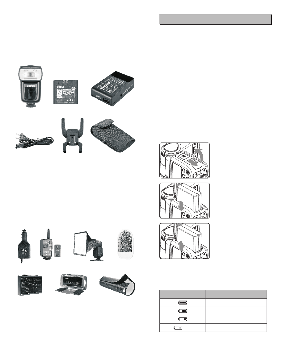
● What’s in the Box of V860C Kit?
Flash unit 2. Li-ion Battery Pack 3. Battery Charger
1.
4. Battery Charger Cable 5. Mini Stand
6. Protection Case 7. Instruction manual
● What’s in the Box of V860C (only flash unit)?
1. Flash unit 5. Mini Stand 6. Protection Case 7. Instruction manual
1
4
2
5
3
6
Battery
● Features
1. This flash unit uses Li-ion polymer battery which has long runtime.
The available charge-and-discharge times are 500.
2. It is reliably safe. The inner circuit is against overcharge,
overdischarge, overcurrent, and short circuit.
3. Take only 2.5 hours to fully charge the battery by using the
standard battery charger.
● Cautions
1. Do not short circuit.
2. Do not expose to rain or immerse into water. This battery is not
water proof.
3. Keep out of reach of children.
4. No over 24 hours’ continuous charging.
5. Store in dry, cool, ventilated places.
6. Do not put aside or into fire.
7. Dead batteries should be disposed according to local regulations.
8. If the battery had ceased using for over 3 months, please make a
full recharge.
● Loading and Unloading the Battery
To load the battery, push the
1
battery compartment cover
downward and open it.
● Separately Sold Accessories
The product can be used in combination with the following
accessories sold separately, so as to achieve best photography
effects:
FT-16S power & trigger control, Car charger, Mini softbox, White &
Silver reflector, Honeycomb, Color gels, Snoot, etc.
According to the triangle sign
2
on the battery pack, insert it
into the compartment until a
white knob locks the battery
with a click sound.
To unload the battery, tap the
3
white knob and the battery
pack will pop out. Then close
the compartment.
● Battery Level Indication
Make sure the battery pack is securely loaded in the flash. Check
the battery level indication on the LCD panel to see the remaining
battery level.
Battery Level Indication
Blinking
- 07 - - 08 -
Meaning
Full
Middle
Low
Battery power will be empty and need
to be charged immediately.
Page 6

Attaching to a Camera
1
2
3
Attach the Camera Flash.
● Slip the camera flash’s
mounting foot into the
camera’s hotshoe all the
way.
Secure the Camera Flash.
● Rotate the lock ring on the
mounting foot until it locks
up.
Detach the Camera Flash.
● Rotate the lock ring on the
mounting foot until it is
loosened.
● Press the camera release button halfway to focus. The shutter
speed and aperture will be displayed in the viewfinder.
● When the shutter button is fully pressed, the flash will fire a pre-
flash that the camera will use to calculate exposure and flash
output the instant before the photo is taken.
When this icon appears on the LCD panel, it means the
flash unit is at the max. power output. If still underexposure,
please make settings on your camera in terms of shutter
speed, aperture, ISO, etc.
FEC: Flash Exposure Compensation
With FEC function, this flash can adjust from -3 to +3 in 1/3rd stops.
It is useful in situations where minor adjusting of the TTL system is
needed based on the environment.
Setting FEC:
Press < > button. The
1
icon < > and flash
exposure compensation
amount will blink on the LCD
panel.
Power Management
Use ON/OFF Power Switch to power the flash unit on or off. Turn off
if it will not be used for an extended period of time. Setting as a
master flash, it will turn the power off automatically after a certain
period (approx. 90 seconds) of idle use. Pressing the camera
shutter halfway or pressing any flash button will wake up the flash
unit. Setting as a slave flash, it will enter sleep mode after a certain
period (adjustable, 60 minutes by default) of idle use. Pressing any
flash button will wake it up.
C.Fn
Disabling Auto Power Off function is recommended
when the flash is used off camera. (C.Fn-01, see P22)
Slave Auto Power Off Timer is set to 60 minutes by
C.Fn
default. Another option “30 minutes” is available. (C.Fn-
10, see P22)
Flash Mode—E-TTL Autoflash
This flash has three flash modes: E-TTL, Manual (M), and Multi
(Stroboscopic). In E-TTL mode, the camera and the flash will work
together to calculate the correct exposure for the subject and the
background. In this mode, multiple TTL functions are available:
FEC, FEB, FEL, HSS, second curtain sync, modeling flash, control
with the camera’s menu screen.
* Press < > Mode Selection Button and three flash modes will
display on the LCD panel one by one with each pressing.
FEB: Flash Exposure Bracketing
You can take three flash shots while automatically changing the
flash output for each shot from -3 to +3 in 1/3rd stops. The camera
will record three images with different exposures: one exposed
according to camera calculations, one over-exposed and another
under-exposed. Over and under exposure amount is user
adjustable. This function helps get correct exposure especially in
shooting moving objects or when environmental lights are complex.
Set the flash exposure
compensation amount.
2
●
Turn the Select Dial to set the
amount.
● To cancel the flash exposure
compensation, set the amount
to “+0”.
Press < > button again to
confirm the setting. Then it
3
turns to FEB settings.
Press < > button. The icon
< > and the exposure
1
bracketing amount will blink
on the LCD panel.
ETTL Mode
Press < > Mode Selection Button to enter E-TTL mode. The
LCD panel will display < ETTL >.
- 09 - - 10 -
Page 7

Set the exposure bracketing
2
amount. Turn the Select Dial to
set the amount.
Press < > button again to
3
confirm the setting. Then
your FEC and FEB settings
are displayed on the LCD
panel.
● FEB will be cancelled after three photos are taken.
●
For best results, set the camera drive mode to “single” and
ensure the flash is ready before shooting.
●
FEB can be used with FEC and FEL.
You can prevent the FEB from being cancelled
C.Fn
automatically after three photos are taken. (C.Fn-03 ,
see P22)
The FEB shooting sequence can be changed. (C.Fn-
C.Fn
04, see P22)
FEL: Flash Exposure Lock
FEL can lock the correct flash exposure setting for any part of the
scene.
With <ETTL> displayed on the LCD panel, press the camera’s
<FEL> button. If the camera does not have the <FEL> button, press
the < * > button.
Focus the subject.
1
Press the <FEL> button.
2
●
Aim the subject at the center of
the viewfinder and press <FEL>
button.
●
The camera flash will fire a
preflash and the required flash
output for the subject is retained
in memory.
●
Each time the <FEL> button is
pressed, a preflash will be fired
and a new flash exposure
setting will be locked.
High-Speed Sync
High Speed Sync (FP flash) enables the flash to synchronize with
all camera shutter speeds. This is convenient when you want to
use aperture priority for fill-flash portraits.
Select < >.
● Press < > button so that
< > is displayed.
● Check that < > is
displayed in the viewfinder.
● If you set a shutter speed that is the same as or slower than
the camera’s maximum flash sync speed, < > will not be
displayed in the viewfinder.
● With high-speed sync, the faster the shutter speed, the
shorter the effective flash range.
● To return to normal flash, press < > button again. Then
< > will disappear.
● Multi flash mode cannot be set in high-speed sync mode.
● Over-temperature protection may be activated after 15
consecutive high-speed sync flashes.
Second-Curtain Sync
With a slow shutter speed, you can create a light train following the
subject. The flash fires right before the shutter closes.
Press < > button so that
< > is displayed on the LCD
panel.
M: Manual Flash
The flash output is adjustable from 1/1 full power to 1/128th power
in 1/3rd stop increments. To obtain a correct flash exposure, use a
hand-held flash meter to determine the required flash output.
Press < > button so that
1
< M > is displayed.
● If the subject is too far away and underexposure, the < >
icon will blink in the viewfinder. Move closer to the subject
and try the FE lock again.
● If <ETTL> is not displayed on the LCD panel, FE lock
cannot be set.
● If the subject is too small, FE lock might not be very
effective.
- 11 - - 12 -
Turn the Select Dial to choose
2
a desired flash output amount.
Page 8

Flash Output Range
The following table makes it easier to see how the stop changes in
terms of f/stop when you increase or decrease the flash output. For
example, when you decrease the flash output to 1/2, 1/2-0.3, or 1/2-
0.7, and then increase the flash output to more than 1/2, 1/2+0.3,
1/2+0.7, and 1/1 will be displayed.
Figures displayed when reducing flash output level→
1/1–0.3
1/1-0.7
1/2+0.7
1/2+0.3
←Figures displayed when increasing flash output level
1/2-0.3
1/4+0.7
1/2-0.7
1/4+0.3
······
1/41/21/1
······
Multi: Stroboscopic Flash
With stroboscopic flash, a rapid series of flashes is fired. It can be
used to capture a multiple images of a moving subject in a single
photograph.
You can set the firing frequency (number of flashes per sec.
expressed as Hz), the number of flashes, and the flash output.
Press < > button so that
1
<MULTI> is displayed.
Turn the Select Dial to choose
2
a desired flash output.
Set the flash frequency and
3
flash times.
●
Press < > button to select the
item (blinks).
●
Turn the Select Dial to set the
number and press < > button
again to confirm. The next item to
be set will blink.
●
After you finish the setting, press
< > button and all the settings
will be displayed.
Calculating the Shutter Speed
During stroboscopic flash, the shutter remains open until the firing
stops. Use the formula below to calculate the shutter speed and set
it with the camera.
Number of Flashes / Flash Frequency = Shutter Speed
For example, if the number of flashes is 10 and the firing frequency is
5 Hz, the shutter speed should be at least 2 seconds.
To ovoid overheating and deteriorating the flash head, do not
use stroboscopic flash more than 10 times in succession.
After 10 times, allow the camera flash to rest for at least 15
minutes. If you try to use the stroboscopic flash more than 10
times in succession, the firing might stop automatically to
protect the flash head. If this happens, allow at least 15
minutes’ rest for the camera flash.
Stroboscopic flash is most effective with a highly reflective
●
subject against a dark background.
Using a tripod and a remote control is recommended.
●
A flash output of 1/1 and 1/2 cannot be set for stroboscopic
●
flash.
Stroboscopic flash can be used with“buLb”.
●
If the number of flashes is displayed as “--”, the firing will
●
continue until the shutter closes or the battery is
exhausted. The number of flashes will be limited as shown
by the following table.
Maximum Stroboscopic Flashes:
Hz
Flash
output
1/4
1/8
1/16
1/32
1/64
1/128
Flash
output
1/4
1/8
1/16
1/32
1/64
1/128
If the number of flashes is displayed as “--”, the maximum number of
flashes will be as shown in the following table regardless of the flash
frequency.
Flash Output
Number of Flashes
1
2
3
4
5
6-7
8-9
7
6
5
4
4
3
3
14
14
12
10
8
6
5
20
20
30
30
30
20
1/16
50
50
80
80
100
100
15-19
20-50
2
4
8
18
35
50
1/32
8
12
60
60
60
90
90
90
100
100
100
Hz
10
11
12-14
2
2
2
4
4
4
8
8
8
20
20
20
50
40
40
70
70
60
1/421/8
4
10
40
30
70
60
90
80
60-199
2
2
4
4
8
8
16
12
30
20
40
40
1/64201/128
40
Wireless Flash
This product supports wireless flash application and functions
as either a master or a slave unit. As a master unit, it can control
Canon speedlites e.g. 580EXII, 600EX-RT via wireless. As a slave
unit, it can receive wireless signals of Canon speedlites e.g.
580EXII, 600EX-RT and commanders of Canon cameras e.g.
7D/60D/600D.
● You can set up two to three slave groups for E-TTL II autoflash
shooting. With E-TTL II autoflash, you can easily create various
lighting effects.
- 13 - - 14 -
Page 9

● Any flash settings (of flash exposure compensation, high-speed
sync, FE lock, FEB, manual flash, Multi flash) on the master unit
will be automatically sent to the slave units. So the only thing you
need to do is to set the master unit to ETTL mode without any
operation for the slave units at all during the shooting.
● This flash can work in ETTL autoflash, M manual flash, and Multi
stroboscopic flash modes when set as a master unit.
Positioning and Operation Range
Indoors
Outdoors
80°
8m(26.2ft) 12m(39.4ft)
● Even with multiple slave units, the master unit can control
all of them via wireless.
●
In this user manual, “master unit” refers to the camera flash
on a camera and “slave unit” will be controlled by the
master unit.
15m(49.2ft)
10m(32.8ft)
1.Wireless Settings
You can switch between normal flash and wireless flash. For normal
flash shooting, be sure to set the wireless setting to OFF.
Master Unit Setting
Press < > button for 2
1
seconds or longer until the
icon in dotted lines blinks.
Set it as the master unit.
2
●
Turn the Select Dial until
< > blinks. Press
the <SET> button to
confirm the settings.
●
< > and < > will
be displayed, meaning the flash
is set as the master unit.
Set it as the slave unit.
2
●
Turn the Select Dial until
< > blinks. Press
the <SET> button to
confirm the settings.
●
< > and < > will
be displayed, meaning the flash
is set as the slave unit.
Optic S1 Secondary Unit Setting
In M manual flash mode, this flash can function as an optic S1
secondary flash with optic sensor. With this function, the flash will fire
synchronously when the main flash fires, the same effect as that by
the use of radio triggers. This helps create multiple lighting effects.
Press < > button for 2
1
seconds or longer until the
icon in dotted lines blinks.
Set it as an optic S1
2
secondary unit.
●
Turn the Select Dial until < S1 >
blinks. Press the < > button to
confirm the settings.
Optic S2 Secondary Unit Setting
The flash can also function as an optic S2 secondary flash with
optic sensor in M manual flash mode. This is useful when cameras
have pre-flash function. With this function, the flash will ignore a
single “preflash” from the main flash and will only fire in response to
the second, actual flash from the main unit.
Press < > button for 2
1
seconds or longer until the
icon in dotted lines blinks.
Set it as an optic S2
2
secondary unit.
●
Turn the Select Dial until < S2 >
blinks. Press the < > button to
confirm the settings.
Slave Unit Setting
Press < > button for 2
1
seconds or longer until the
icon in dotted lines blinks.
- 15 - - 16 -
● S1 and S2 optic triggering is only available in M manual
flash mode.
Page 10

2. Fully Automatic Wireless Flash
This uses E-TTL autoflash to control the total flash output and make
all groups of flashes fire at an average of the total flash output.
Attach a camera flash
1
onto the camera and set
it as the master unit.
3. Master Unit’s Flash OFF
When the master unit is set to OFF, only the slave units will fire a
flash.
Set it as the master unit.
1
Press < > button for
few times until < >
and < > blink.
Set the other camera
2
flash(es) as the wireless
slave unit(s).
Check the communication
3
channel. If the master unit
and slave unit(s) are set
to a different channel, set
them to the same
channel.
Position the camera and
4
flashes.
Set the master unit’s
5
flash mode to <ETTL>.
For shooting, <ETTL>
will automatically be set
for the slave unit(s).
Check that the flash is
6
ready.
Check the flash operation.
Press the master unit’s
7
Test Button and the slave
unit will fire. If not, adjust
the slave unit’s angle
toward the master unit
and distance from the
master unit.
Set the camera in the
8
same way as with
normal flash shooting.
● No matter where the slave unit's flash head is towards, be
sure to make its wireless sensor faces the master unit. Also
ensure that the slave unit is placed within the effective
transmission range of the master unit. Do not place any
obstacles between the master unit and the slave unit(s).
Obstacles may block the transmission of wireless signals.
After positioning the slave unit(s), be sure to test the wireless
●
flash operation before shooting.
Disable the master unit’s
2
flash firing.
Turn the Select Dial until
●
< > is displayed. Press the
< > button to confirm.
● Even if the master unit flash firing is disabled, it still fires a
preflash to transmit wireless signals.
4. Setting the Communication Channel
If there are other wireless flash systems nearby, you can change the
channel IDs to prevent signal interference. The channel IDs of the
master unit and the slave unit(s) must be set to the same.
Press < > button for
1
two times so that < >
blinks.
Set a channel ID.
2
●
Turn the Select Dial to
choose a channel ID and press
the < > button to confirm.
5. Setting the Flash Output for Slave Units
In M manual and Multi stroboscopic flash modes, you can set a
different flash output for each slave unit. All settings are done with
the master unit.
Press < > button to
1
have < M > or < Multi >
displayed.
Press < > button so
2
that < > blinks on the
LCD panel.
- 17 - - 18 -
Page 11

Slave group A
ID= A I D=A
ID= A
Other Applications
Select the flash ratio. Turn
3
the Select Dial to choose
< A:B > or < A:B:C > .
Pressing the < >
button will confirm the
settings.
Set the flash output.
4
●
The flash unit selects < A >
slave ID by default. The
selected ID will be
underlined. After you finish
all the settings for < A >,
press < > button will start
the settings for < B >.
●
Turn the Select Dial to
choose a desired flash
output.
About Slave Group Control
If three slave units are all set to
< A > in terms of slave ID,
these slave units will be
controlled as if they were one
camera flash in slave group A.
Sync Triggering
The Sync Cord Jack is a Φ2.5mm plug. Insert a trigger plug here
and the flash will be fired synchronously with the camera shutter.
Modeling Flash
If the camera has a depth-of-field preview button, pressing it will fire
the flash continuously for 1 second. This is called modeling flash.
It enables you to see the shadow effects on the subject and the
lighting balance. You can fire the modeling flash during wireless or
normal flash shooting.
● To avoid overheating and deteriorating the flash head, do
not fire the modeling flash for more than 10 consecutive
times. If you fire the modeling flash 10 consecutive times,
allow at least 10 minutes’ break for the camera flash.
●
The modeling flash cannot be fired with the EOS 300 and
Type-B cameras.
Auto Focus Assist Beam
In poorly-lit or low-contrast shooting environments, the built-in auto
focus assist beam will automatically light on to make it easier for
autofocus. The beam will light up only when autofocus is difficult
and get out as soon as the autofocus becomes correct.
● If you find the auto focus assist beam does not light up, this
is because the camera has got a correct autofocus.
Position
Center
Periphery
Effective Range
0.6~10m / 2.0~32.8 feet
0.6~5m / 2.0~16.4 feet
Wireless Control Function
The flash unit is built in with a Wireless Control Port so that you can
wirelessly adjust the power level of the flash and the flash triggering.
To control the flash wirelessly, you need a FT-16S
remote control set (on-camera and on-flash).
Insert its receive end into the Wireless Control
Port on the flash and insert the transmit end into
the camera hot shoe. Settings made on the
hotshoe-mounted transmit and receive ends
will be wirelessly communicated
to the flash. Then you can
press the camera shutter
release button to trigger
the flash. You can also hold
the transmit end at hand to
control your off-camera flash.
● When the flash unit receives wireless signals, is shown
on the LCD display.
●
For full instructions on the use of FT series remote control,
see its user manual.
- 19 - - 20 -
Bounce Flash
By pointing the flash head toward a wall or ceiling, the flash will
bounce off the surface before illuminating the subject. This can
soften shadows behind the subject for a more natural-looking shot.
This is called bounce flash.
To set the bounce direction, hold the flash head and turn it to a
satisfying angle.
-7-90
360
Page 12

● If the wall or ceiling is too far away, the bounced flash might
be too weak and result in underexposure.
The wall or ceiling should be a plain, white color for high
●
reflectance. If the bounce surface is not white, a color cast
may appear in the picture.
C.Fn: Setting Custom Functions
The following table lists the available and unavailable custom
functions of this flash. The icon “ √ ” indicates the flash custom
function is supported but “0”indicates the custom function is not
supported.
Creating a Catchlight
With the catchlight panel, you can create a catchlight in the subject’s
eyes to add life to the facial expression.
Point the flash head upward
1
by 90°.
Pull out the wide panel. The
2
catchlight panel will come out
at the same time.
Push the wide panel back in.
Custom
Functions No.
C.Fn-00
C.Fn-01
C.Fn-02
3
●
Push in only the wide panel.
●
Follow the same procedures as
for bounce flash.
● Point the flash head straight ahead and then upward by
90°. The catchlight will not appear if you swing the flash
head left or right.
For best catchlight effect, stay 1.5m/4.9ft away from the
●
subject.
ZOOM: Setting the Flash Coverage and Using
the Wide Panel
The flash coverage can be set automatically or manually. It can be
set to match the lens focal length from 24 mm to 105mm. Also, with
the built-in wide panel, the flash coverage can be expanded for
14mm wide-angle lenses.
If you set the flash coverage manually, make sure it covers
the lens focal length so that the picture will not have a dark
periphery.
- 21 - - 22 -
In Manual Zoom mode,
press the < > button.
●
Turn the Select Dial to
change the flash coverage.
If < > is not displayed, the
flash coverage will be set
automatically.
Using the Wide Panel
Pull out the wide panel and place it
over the flash head as shown. The
flash coverage will then be extended
to 14 mm.
●
The catchlight panel will come out
at the same time. Push the
catchlight panel back in.
●
The < > button will not work.
C.Fn-03
C.Fn-04
C.Fn-05
C.Fn-06
C.Fn-07
C.Fn-08
C.Fn-09
C.Fn-10
C.Fn-11
C.Fn-12
C.Fn-13
C.Fn Custom Functions
Function
Distance indicator
display
Auto power off
Modeling flash
FEB auto cancel
FEB sequence
Flash metering mode
Quickflash with
continuous shot
Test firing with
autoflash
AF-assist beam firing
Auto zoom for
sensor size
Slave auto power
off timer
Slave auto power
off cancel
Flash recycle with
external power source
Flash exposure
metering setting
Setting
No.
0
1
0
1
Enabled (Depth-of-field
0
1
(Test firing button)
2
(with both buttons)
3
0
1
0
1
0
1
External metering:
2
External metering:
3
0
1
0
1
0
1
0
1
0
1
0
1
Flash and external power
0
External power source
1
Speedlite button and dial
0
Speedlite dial only
1
Settings &
Description
Meters (m)
Feet (ft)
Enabled
Disabled
preview button)
Enabled
Enabled
Disabled
Enabled
Disabled
0 -> − -> +
- -> 0 -> +
E-TTL II/E-TTL
TTL
Auto
Manual
Disabled
Enabled
1/32
Full output
Enabled
Disabled
Enabled
Disabled
60 minutes
30 minutes
Within 8 hours
Within 1 hour
Support
or Not
0
√
0
√
√
0
0
0
0
0
√
0
0
0
Page 13

Press < > button for
1
2 seconds or longer until
< > is displayed.
Select the Custom Function
2
No.
● Turn the Select Dial to set
the Custom Function No.
Change the setting.
3
● Press< > button and
the setting No. blinks.
● Turn the Select Dial to set
the desired number.
Pressing < > button will
confirm the settings.
● After you set the Custom
Function and press < >
button, the camera will be
ready to shoot.
Control with the Camera’s Menu Screen
If the camera flash is attached to an EOS camera which has a
speedlite control function, the flash can be controlled using the
camera’s menu screen. For the menu operation procedure, refer to
your camera’s instruction manual.
●
Setting Camera Flash Functions
The following flash functions are settable according to different
flash modes.
1. Flash mode
2. Shutter sync (1st/2nd curtain, high speed sync)
3. FEB
4. Flash exposure compensation
5. Flash firing
6. Clear camera flash’s settings
●
Custom Functions of Camera Flash
C.Fn-01, C.Fn-03, C.Fn-04, and C.Fn-10
Clear All Flash Custom Functions
Flash function settings screen Flash C.Fn settings screen
Protection Function
1. Over-Temperature Protection
● To avoid overheating and deteriorating the flash head, do not fire
more than 30 continuous flashes in fast succession at 1/1 full
power. After 30 continuous flashes, allow a rest time of at least 10
minutes.
● If you fire more than 30 continuous flashes and then fire more
flashes in short intervals, the inner over-temperature protection
function may be activated and make the recycling time about 10
to 15 seconds. If this occurs, allow a rest time of about 10
minutes, and the flash unit will then return to normal.
● When the over-temperature protection is started, is shown on
the LCD display.
Number of flashes that will activate over-temperature
protection:
Power Output Level
1/1
1/2 +0.7
1/2 +0.3
1/2
1/4(+0.3,+0.7)
1/8(+0.3,+0.7)
1/16(+0.3,+0.7)
1/32(+0.3,+0.7)
1/64(+0.3,+0.7)
1/128(+0.3,+0.7)
Number of flashes that will activate over-temperature
protection in high-speed sync triggering mode:
Power Output
1/1
1/2(+0.3,+0.7);
1/4(+0.3,+0.7)
1/8(+0.3,+0.7);
1/16(+0.3,+0.7)
1/32(+0.3,+0.7);
1/64(+0.3,+0.7);
1/128(+0.3,+0.7);
Number of Flashes
30
40
50
60
100
200
300
500
1000
Times
15
20
30
40
50
2. Other Protections
The system provides real-time protection to secure the device and
your safety. The following lists prompts for your reference:
* Screens from the EOS-1D Mark III.
● If flash exposure compensation has already been set with
the camera flash, flash exposure compensation cannot be
set with the camera. To set it with the camera, the camera
flash’s flash exposure compensation must be set to zero.
●
If any Flash Custom Functions and flash settings other
than flash exposure compensation have been set by both
the camera and the flash, the latest settings will take effect.
- 23 - - 24 -
Prompts on LCD Panel
E1
E2
E3
Meaning
A failure occurs on the recycling system so that the
flash cannot fire.
Please restart the flash unit. If the problem still exists,
please send this product to a maintenance center.
The system gets excessive heat. Please allow a rest
time of 10 minutes.
The voltage on two outlets of the flash tube is too high.
Please send this product to a maintenance center.
Page 14

Technical Data
Troubleshooting
Kit Model
Flash-Only Model
• Type
Compatible Cameras
Guide No.
(1/1 output @ 105mm)
Flash Coverage
Flash Duration
• Exposure Control
Exposure control system
Flash exposure
compensation (FEC)
FE lock
Sync mode
Multi flash
• Wireless Flash
Wireless flash function
Controllable slave groups
Transmission range
(approx.)
Channels
Slave-ready indicator
Modeling flash
• Auto Focus Assist Beam
Effective range (approx.)
• Power Supply
Power source
Recycle time
Full power flashes
Power saving
• Sync Triggering Mode
• Color Temperature
• Dimensions
W x H x D
Weight without battery
Weight with battery
V860C Kit (with battery & charger)
V860C (only flash unit)
Canon EOS cameras (E-TTL II autoflash)
58 (m ISO 100)
190 (feet ISO 100)
24 to 105mm (14mm with wide panel)
• Auto zoom (Flash coverage set automatically
to match the lens focal length and image size)
• Manual zoom
• Swinging/tilting flash head (bounce flash): 0 to 360°
horizontally and -7° to 90° vertically
1/300 to 1/20000 seconds
E-TTL II autoflash and manual flash
Manual. FEB: ±3 stops in 1/3 stop increments
(Manual FEC and FEB can be combined.)
With <FEL> button or< * > button
High-speed sync (up to 1/8000 seconds),
first-curtain sync, and second-curtain sync
Provided (up to 100 times, 199Hz)
Master, Slave, Off
3 (A, B, and C)
Indoors: 12 to 15 m / 39.4 to 49.2 ft.
Outdoors: 8 to 10 m / 26.2 to 32.8 ft.
Master unit reception angle: ±40° horizontally,
±30° vertically
4 (1, 2, 3, and 4)
Two red indicators blink
Fired with camera’s depth-of-field preview button
Center: 0.6~10m / 2.0~32.8 feet
Periphery: 0.6~5m / 2.0~16.4 feet
11.1V/2000mAh Li-ion polymer battery
< 1.5 seconds. Red LED indicator will light up
when the flash is ready.
Approx. 650
Power off automatically after approx. 90 seconds
of idle operation. (60 minutes if set as slave)
Hotshoe, 2.5mm sync line, Wireless control port
5600±200k
64*76*190 mm
420g
540g
If there is a problem, refer to this Troubleshooting Guide.
The Camera Flash cannot be charged.
● The battery is installed in the wrong direction.
→Install the battery in the correct direction.
● The camera flash’s internal battery is exhausted.
→If < > appears and blinks on the LCD panel, replace the
battery immediately.
The Camera Flash does not fire.
● The camera flash is not attached securely to the camera.
→Attach the camera’s mounting foot securely to the camera.
● The electrical contacts of the Camera Flash and camera are dirty.
→Clean the contacts.
● < > or < > is not displayed in the view finder of camera.
→Wait until the flash is fully recycled and the flash ready indicator
lights up.
→If the flash ready indicator lights up, but < > or < > is not
displayed in the view finder, check whether this flash unit is
securely attached to the camera hotshoe.
→If the flash ready indicator does not light up after a long wait,
check whether the battery power is enough. If the battery power is
low, < > will appear and blink on the LCD panel. Please
replace the battery immediately.
The power turns off by itself.
● After 90 seconds of idle operation, auto power off took effect if the
flash is set as master.
→Press the shutter button halfway or press any flash button to
wake up.
● After 60 minutes (or 30 minutes) of idle operation, the flash unit
will enter sleep mode if it is set as slave.
→Press any flash button to wake up.
Auto zoom does not work.
● The camera flash is not attached securely to the camera.
→Attach the camera flash’s mounting foot to the camera.
The flash exposure is underexposed or overexposed.
● There was a highly reflective object (e.g. glass window) in the
picture.
→Use FE lock (FEL).
● You used high-speed sync.
→With high-speed sync, the effective flash range will be shorter.
Make sure the subject is within the effective flash range
displayed.
● You used Manual Flash mode.
→Set the flash mode to ETTL or modify the flash output.
- 25 - - 26 -
Page 15

Photos have dark corners or only parts of the target subject
are illuminated.
The focal length of lens exceeds the flash coverage.
●
→Check the flash coverage you set. This flash unit has the flash
coverage between 24 and 105mm, which fits medium-format
cameras. Pull the wide panel out to extend the flash coverage.
Firmware Upgrade
This flash supports firmware upgrade through the USB port. Update
information will be released on our official website.
USB connection line is not included in this product. The USB
port is a standard Micro USB socket. Common USB
connection line is applicable.
Compatible Camera Models
This flash unit can be used on the following
Canon EOS series camera models:
5D Mark III 5D Mark II
600D 550D 500D 450D
This table only lists the tested camera models, not all Canon
EOS series cameras. For the compatibility of other camera
models, a self-test is recommended.
Rights to modify this table are retained.
6D7D60D 50D 40D
400D Digital
30D
1100D 1000D
650D
Maintenance
Shut down the device immediately should abnormal operation be
●
detected.
● Avoid sudden impacts and the product should be dedusted
regularly.
● It is normal for the flash tube to be warm when in use. Avoid
continuous flashes if unnecessary.
● Maintenance of the flash must be performed by our authorized
maintenance department which can provide original accessories.
● This product, except consumables e.g. flash tube, is supported
with a one-year warranty.
● Unauthorized service will void the warranty.
● If the product had failures or was wetted, do not use it until it is
repaired by professionals.
● Changes made to the specifications or designs may not be
reflected in this manual.
- 27 -
 Loading...