

Page 1
TTL
锂电机顶闪光灯
Pioneering Camera FlashTTL Li-ion
For Canon
深圳市神牛摄影器材有限公司
GODOX Photo Equipment Co., Ltd.
地址/Add: 深圳市宝安区福永镇福洲大道西新和村华发工业园A4栋
Building A4, Xinhe Huafa Industrial Zone, Fuzhou RD West, Fuyong
Town, Baoan District, Shenzhen 518103, China
电话/Tel: +86-755-29609320(8062) 传真/Fax: +86-755-25723423
邮箱/E-mail: godox@godox.com
http://www.godox.com
705-V8602C-00
Made In China
INSTRUCTION MANUAL
说 明 手 册
中英文双语 / Chinese English Bilingual
在使用本产品之前:
请先仔细阅读本手册,以确保您能安全使用。请保存好本手册以备将
来查询参考。
Before using this product:
Please read this user manual carefully in order to ensure your safety
and the proper operation of this product. Keep for future reference.
Page 2
固件升级
Foreword
本机通过USB插座可进行固件升级。软件最新公告及说明将会发布在
官方网站上。
注:本品出厂不配USB升级线,请另行购买。普通的USB线可
使用,本产品USB口为Micro USB 接口。
兼容相机列表
本机可兼容以下佳能EOS系列的相机型号:
1DX
5D Mark III 5D Mark II
600D 550D 500D 450D
650D
注:
1. 此表格仅列举目前已测试的相机型号,未涵盖所有佳能EOS
系列相机。其他相机型号,用户可自行测试。
2. 本公司保留未来修改此表格内容的权利。
6D 7D 60D 50D 40D 30D
400D Digital
1100D 1000D
维护保养
● 闪光灯在工作时,如发现异常,应立即关掉电源,查明原因。
● 灯体应避免震动,平时注意表面除尘。
● 灯体稍有发热为正常现象,无特别需要时,勿连续引闪。
● 闪光灯的所有维修概由本厂指定可供原厂配件之维修部负责。
● 1年保修,消耗品如灯管等,不在1年保修范围。
● 经发现,擅自检修此闪光灯的,将取消闪光灯之一年保修期,维修
需要收取相关费用。
● 如果本品出现故障或者 被水淋湿 ,在专业人员维修后方可继续 使
用。
● 如有技术更改,恕不另行通知。
Thank you for purchasing this product.
This V860IIC camera flash applies to Canon EOS series cameras
and is compatible with E-TTL II autoflash. With this E-TTL II
compatible flash, your shooting will become simpler. You can easily
achieve a correct flash exposure even in complex light-changing
environments. This camera flash features:
● GN60 (m ISO 100, @200mm). 22 steps from 1/1 to 1/128.
● Pro 2000mAh Li-ion Battery-max.1.5s recycle-650 full power pops.
● Fully support Canon E-TTL II camera flash. Workable as Master or
Slave unit in a wireless flash group.
● Use dot-matrix LCD panel to make clear and convenient
operations.
● With built-in 2.4GHz wireless remote system to support
transmitting and receiving.
● Provided multiple functions, include HSS (up to 1/8000s), FEC,
FEB, etc.
● Use optional FT-16S to adjust flash parameters & trigger the flash.
● Stable consistency and color temperature with good even lighting.
● Support with firmware upgrade.
For Your Safety
Always keep this product dry. Do not use in rain or in damp
conditions.
This product contains high-voltage electronic parts. Touching
the high-voltage circuit inside it may result in electric shock. Do
not disassemble. Should repairs become necessary, this
product must be sent to an authorized maintenance center.
Stop using this product if it breaks open due to extrusion, falling
or strong hit. Otherwise, electric shock may occur if you touch
the electronic parts inside it.
Do not fire the flash directly into the eyes (especially those of
babies) within short distances. Otherwise visual impairment
may occur. When taking pictures for babies, keep the flash unit
at least 1 meter (3.3 feet) away from them. Using bounce flash
to reduce light intensity is also recommended.
Do not use the flash unit in the presence of flammable gases,
chemicals and other similar materials. In certain circumstances,
these materials may be sensitive to the strong light emitting
from this flash unit and fire or electromagnetic interference may
result.
Do not leave or store the flash unit in places where the ambient
temperature reads over 50°C (e.g. in automobile). Otherwise
the electronic parts may be damaged.
- 41 - - 42 -
Page 3

Pioneering Li-ion Camera Flash
Conventions used in this Manual
● This manual is based on the assumption that both the camera
and camera flash’s power switches are powered on.
● Reference page numbers are indicated by “p.**”.
● The following alert symbols are used in this manual:
The Caution symbol gives supplemental information.
The Note symbol indicates a warning to prevent shooting
problem.
Foreword
42
For Your Safety
42
Name of Parts
45
Body
Control Panel
Dot-matrix LCD Panel
LCD Panel in Five Modes
What's in the Box of V860IIC Kit?
What's in the Box of V860IIC (only flash unit)?
Separately Sold Accessories
Contents
Battery
49
Attaching to a Camera
50
Power Management
50
Flash Mode — E-TTL Autoflash
51
FEC (Flash Exposure Compensation)
FEB (Flash Exposure Bracketing)
FEL: Flash Exposure Lock
High-Speed Sync
Second-Curtain Sync
M: Manual Flash
54
Multi: Stroboscopic Flash
55
Wireless Flash Shooting: Radio (2.4G) Transmission
56
Wireless Settings
Master Unit's Flash OFF
Setting the Communication Channel
ETTL: Fully Automatic Wireless Flash Shooting
ETTL: Use the Wireless Flash Shooting of Flash Ratio
M: Wireless Flash Shooting with Manual Flash
Multi: Wireless Flash Shooting with Manual Flash
Gr: Shooting with a Different Flash Mode for Each Group
Wireless Flash Shooting: Optic Transmission
67
Wireless Settings
Master Unit's Flash OFF
Setting the Communication Channel
ETTL: Fully Automatic Wireless Flash Shooting
ETTL: Use the Wireless Flash Shooting of Flash Ratio
M: Wireless Flash Shooting with Manual Flash
Multi: Wireless Flash Shooting with Manual Flash
Other Applications
74
Wireless Control Function
Sync Triggering
Modeling Flash
Auto Focus Assist Beam
Bounce Flash
Creating a Catchlight
ZOOM: Setting the Flash Coverage and Using the Wide Panel
Low Battery Indicator
C.Fn: Setting Custom Functions
77
Control with the Camera's Menu Screen
78
Protection Function
79
Technical Data
80
Troubleshooting
81
Firmware Upgrade
82
Compatible Camera Models
82
Maintenance
82
- 43 -
- 44 -
Page 4
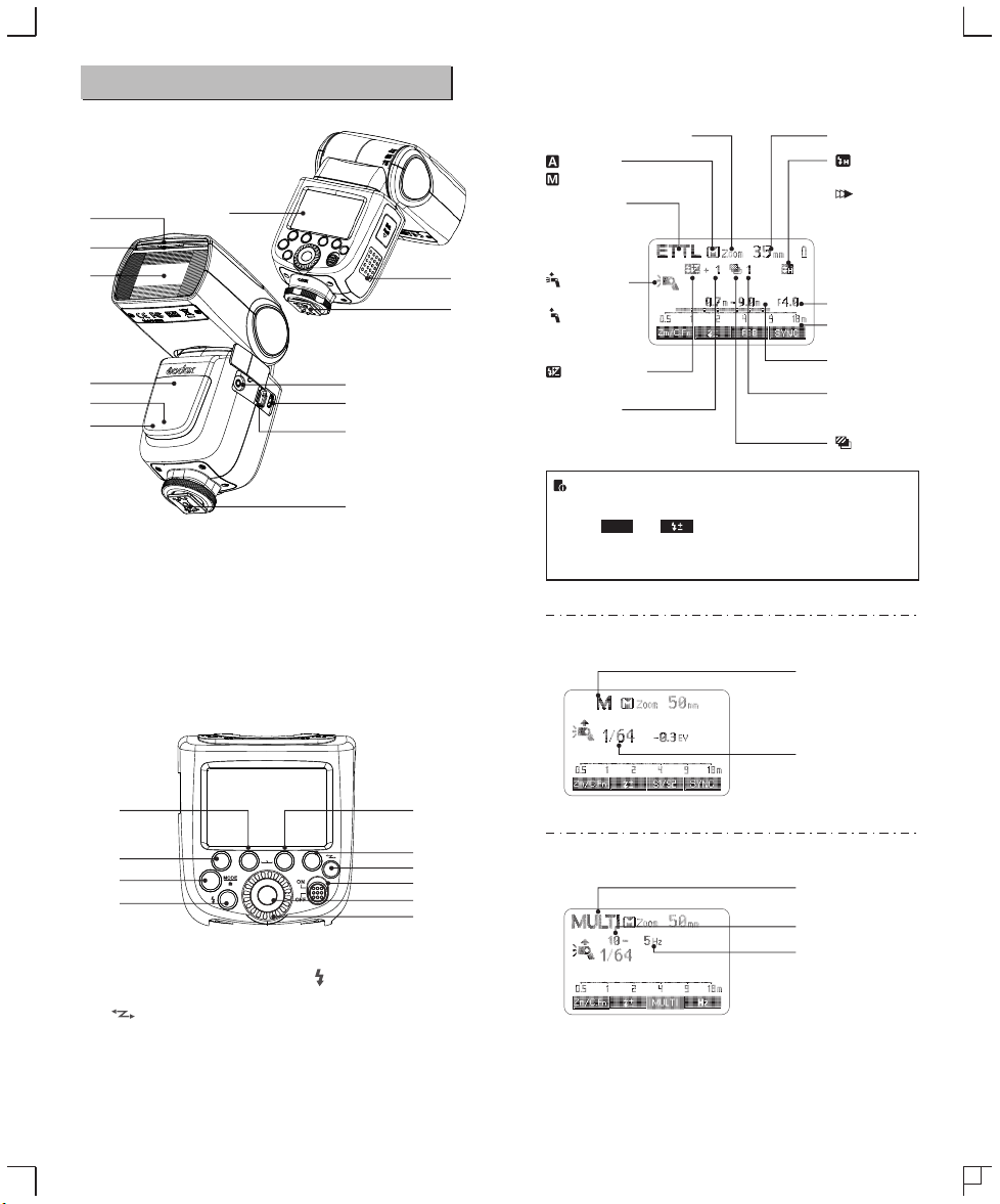
Name of Parts
01
02
03
04
05
13
● Body
01. Catchlight Panel
02. Built-in Wide Panel
03. Flash Head
04. Optic Control Sensor
05. Focus Assist Beam
06. Sync Cord Jack
07. Wireless Control Port
● LCD Panel
(1)E-TTL Autoflash
Zoom : zoom display (Page 76)
: Automatic
: Manual(Page 54)
09
11
10
06
12
07
ETTL : E-TTL II
autoflash
: Master unit
flash ON
: Master unit
flash OFF
: Flash exposure
compensation (Page 51)
Flash exposure
compensation amount
● The display will only show the settings currently applied.
08
08. Hotshoe
09. Dot-marix LCD Panel
● The functions displayed above function buttons 1 to 4, such
as and , change according to settings’ status.
SYNC
● When a button or dial is operated, the LCD panel
illuminated.
10. Lock Ring
11. Battery Compartment
12. USB Port
13. Slave Flash Ready Indicator
(2)M Manual Flash
Focus length (Page )76
: High-speed sync
(Page 53)
: Second curtain
sync (Page 53)
F : Aperture (Page 51)
Distance indicator
display
Effective flash range
(Page 51)
Flash exposure
bracketing sequence
(Page 52)
: Flash exposure
bracketing
M : Manual flash
21
20
14
19
● Control Panel
14. <MODE> Mode Selection
Button / Lock button
15. < >Wireless Selection
Button
16. Select Dial
17. <SET> Set Button
18. ON/OFF Power Switch
- 45 -
RST
SET
19. < > Test Button / Flash
Ready Indicator
20. Function Button 1
21. Function Button 2
22. Function Button 3
23. Function Button 4
Manual flash output
22
23
15
18
17
16
(3)Multi Flash
Multi : Stroboscopic flash
Number of flashes
Flash frequency
- 46 -
Page 5
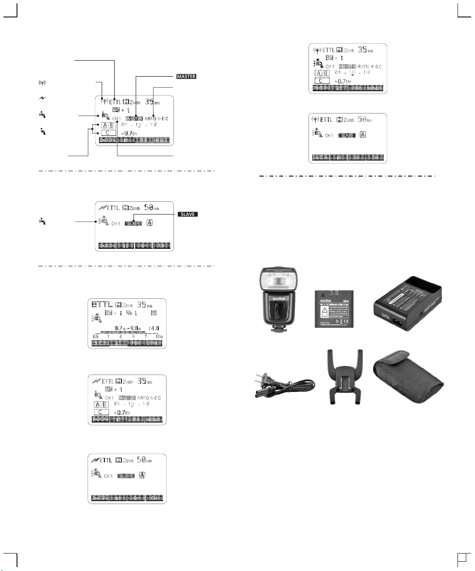
(4) Radio Transmission Shooting/Optic Transmission Shooting
● Master Unit
Flash mode
: Group flash (radio transmission)Gr
: Radio transmission
wireless shooting
: Optic transmission
wireless shooting
: Master unit
flash ON
: Master unit
flash OFF
: Master
RATIO : Flash ratio
● 2.4G Radio Transmission: As a Master Unit
● 2.4G Radio Transmission: As a Slave Unit
Firing group
● Slave Unit
: Slave icon
● LCD Panel in Five Modes
● Attached to the Camera
● Optical Transmission: As a Master Unit
Channel
: Slave
● What’s in the Box of V860IIC Kit?
1. Flash Unit 2. Li-ion Battery Pack 3. Battery Charger
4. Battery Charger Cable 5. Mini Stand
6. Protection Case 7. Instruction Manual
● What’s in the Box of V860IIC (only flash unit)?
1. Flash Unit 5. Mini Stand 6. Protection Case 7. Instruction Manual
1
4
2
5
3
6
● Optical Transmission: As a Slave Unit
- 47 -
- 48 -
Page 6
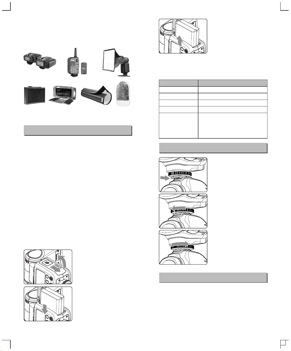
● Separately Sold Accessories
The product can be used in combination with the following accessories
sold separately, so as to achieve best photography effects:
X1C TTL wireless flash trigger, FT-16S power & trigger control, Mini
softbox, White & Silver reflector, Honeycomb, Color gels, Snoot, etc.
Battery
● Features
1. This flash unit uses Li-ion polymer battery which has long runtime.
The available charge-and-discharge times are 500.
2. It is reliably safe. The inner circuit is against overcharge,
overdischarge, overcurrent, and short circuit.
3. Take only 2.5 hours to fully charge the battery by using the
standard battery charger.
● Cautions
1. Do not short circuit.
2. Do not expose to rain or immerse into water. This battery is not
water proof.
3. Keep out of reach of children.
4. No over 24 hours’ continuous charging.
5. Store in dry, cool, ventilated places.
6. Do not put aside or into fire.
7. Dead batteries should be disposed according to local regulations.
8. If the battery had ceased using for over 3 months, please make a
full recharge.
● Loading and Unloading the Battery
To load the battery, push the
1 battery compartment cover
downward and open it.
To unload the battery, tap the
3 white knob and the battery
pack will pop out. Then close
the compartment.
● Battery Level Indication
Make sure the battery pack is securely loaded in the flash. Check
the battery level indication on the LCD panel to see the remaining
battery level.
Battery Level Indication
3 grids
2 grids
1 grid
Blank grid
Blinking
Attaching to a Camera
Meaning
Full
Middle
Low
Lower battery, please recharge it.
The battery level is going to be used out
immediately. And the flash will auto power off
in 1 minute.
Note: Please recharge the battery as soon as
possible (within 10 days). Then, the battery can be
used or be placed for long period.
Attach the Camera Flash.
1
● Slip the camera flash’s
mounting foot into the
camera’s hotshoe all the
way.
Secure the Camera Flash.
2
● Rotate the lock ring on the
mounting foot until it locks
up.
Detach the Camera Flash.
3
● Rotate the lock ring on the
mounting foot until it is
loosened.
Power Management
According to the triangle sign
2 on the battery pack, insert it
into the compartment until a
white knob locks the battery
with a click sound.
- 49 - - 50 -
Use ON/OFF Power Switch to power the flash unit on or off. Turn off
if it will not be used for an extended period of time. Setting as a
master flash, it will turn the power off automatically after a certain
period (approx. 90 seconds) of idle use. Pressing the camera
shutter halfway or pressing any flash button will wake up the flash
unit. Setting as a slave flash, it will enter sleep mode after a certain
period (adjustable, 60 minutes by default) of idle use. Pressing any
flash button will wake it up.
Page 7
C.Fn
Disabling Auto Power Off function is recommended
when the flash is used off camera. (C.Fn-APO, Page 77)
Slave Auto Power Off Timer is set to 60 minutes by
C.Fn
default. Another option “30 minutes” is available. (C.Fn-
Sv APOT, Page 77)
Flash Mode—E-TTL Autoflash
This flash has three flash modes: E-TTL, Manual (M), and Multi
(Stroboscopic). In E-TTL mode, the camera and the flash will work
together to calculate the correct exposure for the subject and the
background. In this mode, multiple TTL functions are available:
FEC, FEB, FEL, HSS, second curtain sync, modeling flash, control
with the camera’s menu screen.
* Press < MODE > Mode Selection Button and three flash modes
will display on the LCD panel one by one with each pressing.
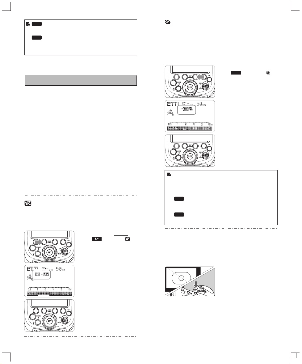
FEB: Flash Exposure Bracketing
You can take three flash shots while automatically changing the
flash output for each shot from -3 to +3 in 1/3rd stops. The camera
will record three images with different exposures: one exposed
according to camera calculations, one over-exposed and another
under-exposed. Over and under exposure amount is user
adjustable. This function helps get correct exposure especially in
shooting moving objects or when environmental lights are complex.
Press function button 3
FEB
1 < >. The icon < >
and the exposure bracketing
amount will be highlighted on
the LCD panel.
Set the flash exposure
2 compensation amount.
● Turn the Select Dial to set
the amount.
● “0.3”means 1/3 step,
“0.7”means 2/3 step.
Press < SET > button again
3 to confirm the setting. Then
ETTL Mode
Press < MODE > Mode Selection Button to enter E-TTL mode. The
LCD panel will display.
● Press the camera release button halfway to focus. The aperture
and effective flash range will be displayed in the viewfinder.
● When the shutter button is fully pressed, the flash will fire a pre-
flash that the camera will use to calculate exposure and flash
output the instant before the photo is taken.
FEC: Flash Exposure Compensation
With FEC function, this flash can adjust from -3 to +3 in 1/3rd stops.
It is useful in situations where minor adjusting of the TTL system is
needed based on the environment.
Setting FEC:
Press Function Button 2
1 < >. The icon < >
and flash exposure
compensation amount will be
highlighted on the LCD
panel.
Set the flash exposure
● FEB will be cancelled after three photos are taken.
● For best results, set the camera drive mode to “single” and
ensure the flash is ready before shooting.
● FEB can be used with FEC and FEL.
You can prevent the FEB from being cancelled
C.Fn
automatically after three photos are taken. (C.FnFEB ACL , Page 77)
The FEB shooting sequence can be changed. (C.Fn-
C.Fn
FEB, Page 77)
FEL: Flash Exposure Lock
FEL can lock the correct flash exposure setting for any part of the
scene.
With <ETTL> displayed on the LCD panel, press the camera’s
<FEL> button. If the camera does not have the <FEL> button, press
the < * > button.
2 compensation amount.
● Turn the Select Dial to set
the amount.
● “0.3”means 1/3 step,
“0.7”means 2/3 step.
● To cancel the flash
exposure compensation,
set the amount to “+0”.
Press < SET > button again
3 to confirm the setting.
- 51 - - 52 -
your FEC and FEB settings
are displayed on the LCD
panel.
Focus the subject.
1
Press the <FEL> button.
2
● Aim the subject at the center of
the viewfinder and press <FEL>
button.
● The camera flash will fire a
preflash and the required flash
output for the subject is retained
in memory.
● Each time the <FEL> button is
pressed, a preflash will be fired
and a new flash exposure
setting will be locked.
Page 8

● If the subject is too far away and underexposure, the < >
icon will blink in the viewfinder. Move closer to the subject
and try the FE lock again.
● If <ETTL> is not displayed on the LCD panel, FE lock
cannot be set.
● If the subject is too small, FE lock might not be very
effective.
High-Speed Sync
High Speed Sync (FP flash) enables the flash to synchronize with all
camera shutter speeds. This is convenient when you want to use
aperture priority for fill-flash portraits.
Press Function Button 2
SYNC
1 < > so that < > is
displayed.
Check that < > is
2 displayed in the viewfinder.
● If you set a shutter speed that is the same as or slower than
the camera’s maximum flash sync speed, < > will not be
displayed in the viewfinder.
● With high-speed sync, the faster the shutter speed, the
shorter the effective flash range.
● To return to normal flash, press < > button again. Then
< > will disappear.
● Multi flash mode cannot be set in high-speed sync mode.
● Over-temperature protection may be activated after 15
consecutive high-speed sync flashes.
Second-Curtain Sync
With a slow shutter speed, you can create a light train following the
subject. The flash fires right before the shutter closes.
SYNC
Press function button 4 < >
button so that < > is displayed
on the LCD panel.
SYNC
M: Manual Flash
The flash output is adjustable from 1/1 full power to 1/128th power
in 1/3rd stop increments. To obtain a correct flash exposure, use a
hand-held flash meter to determine the required flash output.
Press < MODE > button so
1 that < M > is displayed.
Turn the Select Dial to choose
2 a desired flash output amount.
Press < SET > button again to
3 confirm the setting.
Flash Output Range
The following table makes it easier to see how the stop changes in
terms of f/stop when you increase or decrease the flash output. For
example, when you decrease the flash output to 1/2, 1/2-0.3, or 1/2-
0.7, and then increase the flash output to more than 1/2, 1/2+0.3,
1/2+0.7, and 1/1 will be displayed.
Figures displayed when reducing flash output level→
1/1-0.7
1/1-0.3
1/2+0.3
1/2+0.7
←Figures displayed when increasing flash output level
Optic S1 Secondary Unit Setting
In M manual flash mode, press <S1/S2> button so that this flash can
function as an optic S1 secondary flash with optic sensor. With this
function, the flash will fire synchronously when the main flash fires,
the same effect as that by the use of radio triggers. This helps create
multiple lighting effects.
Optic S2 Secondary Unit Setting
Press <S1/S2> button so that this flash can also function as an optic
S2 secondary flash with optic sensor in M manual flash mode. This
is useful when cameras have pre-flash function. With this function,
the flash will ignore a single “preflash” from the main flash and will
only fire in response to the second, actual flash from the main unit.
● S1 and S2 optic triggering is only available in M manual
flash mode.
1/2-0.3
1/4+0.7
1/2-0.7
1/4+0.3
······
1/41/21/1
······
- 53 -
- 54 -
Page 9

Multi: Stroboscopic Flash
With stroboscopic flash, a rapid series of flashes is fired. It can be
used to capture a multiple images of a moving subject in a single
photograph.
You can set the firing frequency (number of flashes per sec.
expressed as Hz), the number of flashes, and the flash output.
Press <MODE> button so
1 that < > is displayed.
MULTI
Turn the Select Dial to choose
2 a desired flash output.
Set the flash frequency and
3 flash times.
MULTI
● Press < > button to
select the item (blinks).
● Turn the Select Dial to set
the number and press
Hz
< > button again to
confirm. The next item to be
set will blink.
● After you finish the setting,
press <SET> button and all
the settings will be
displayed.
Calculating the Shutter Speed
During stroboscopic flash, the shutter remains open until the firing
stops. Use the formula below to calculate the shutter speed and set
it with the camera.
Number of Flashes / Flash Frequency = Shutter Speed
For example, if the number of flashes is 10 and the firing frequency is
5 Hz, the shutter speed should be at least 2 seconds.
To avoid overheating and deteriorating the flash head, do not
use stroboscopic flash more than 10 times in succession.
After 10 times, allow the camera flash to rest for at least 15
minutes. If you try to use the stroboscopic flash more than 10
times in succession, the firing might stop automatically to
protect the flash head. If this happens, allow at least 15
minutes’ rest for the camera flash.
● Stroboscopic flash is most effective with a highly reflective
subject against a dark background.
● Using a tripod and a remote control is recommended.
● A flash output of 1/1 and 1/2 cannot be set for stroboscopic
flash.
● Stroboscopic flash can be used with“buLb”.
● If the number of flashes is displayed as “--”, the firing will
continue until the shutter closes or the battery is
exhausted. The number of flashes will be limited as shown
by the following table.
Maximum Stroboscopic Flashes:
Hz
Flash
output
1/4
1/8
1/16
1/32
1/64
1/128
Flash
output
1/4
1/8
1/16
1/32
1/64
1/128
If the number of flashes is displayed as “--”, the maximum number of
flashes will be as shown in the following table regardless of the flash
frequency.
Flash Output
Number of Flashes
1
2
3
4
5
6-7
8-9
7
6
5
4
4
3
3
14
14
12
10
8
6
5
30
30
30
20
20
20
10
60
60
60
50
50
40
30
90
90
90
80
80
70
60
100
100
100
100
Hz
10
11
12-14
15-19
2
2
2
4
4
4
8
8
8
20
20
20
50
40
40
70
70
60
1/421/8
1/16
8
4
2
4
8
18
35
50
1/32
100
12
90
20-50
60-199
2
4
8
16
30
40
1/64201/128
80
2
4
8
12
20
40
40
Wireless Flash Shooting: Radio (2.4G) Transmission
● When the camera’s shooting mode is set to a fully automatic
mode or an Image Zone mode, the operations in this
chapter are not available. Set the camera’s shooting mode
to P/Tv/Av/M/B (Creative Zone Mode).
● The V860IIC attach to the camera is called the master unit,
and a V860IIC that is wirelessly controlled is called the
slave unit.
● You can also wirelessly control the V860IIC set as the slave
unit with the transmitter X1T-C (sold separately). For details
on setting the master unit functions, see the transmitter’s
instructions.
Using a flash (master/slave) with a radio transmission wireless
shooting function make it easy to shoot with advanced wireless
multiple flash lighting, in the same way as E-TTL II autoflash
shooting.
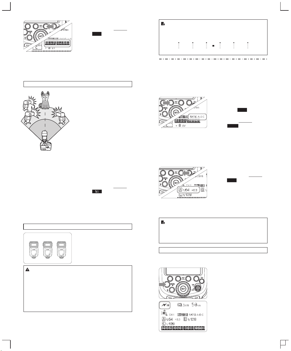
The basic relative position and operation range are as shown in the
picture. You can then perform wireless E-TTL II autoflash shooting
just by setting the master unit to <ETTL>.
- 55 -
- 56 -
Page 10
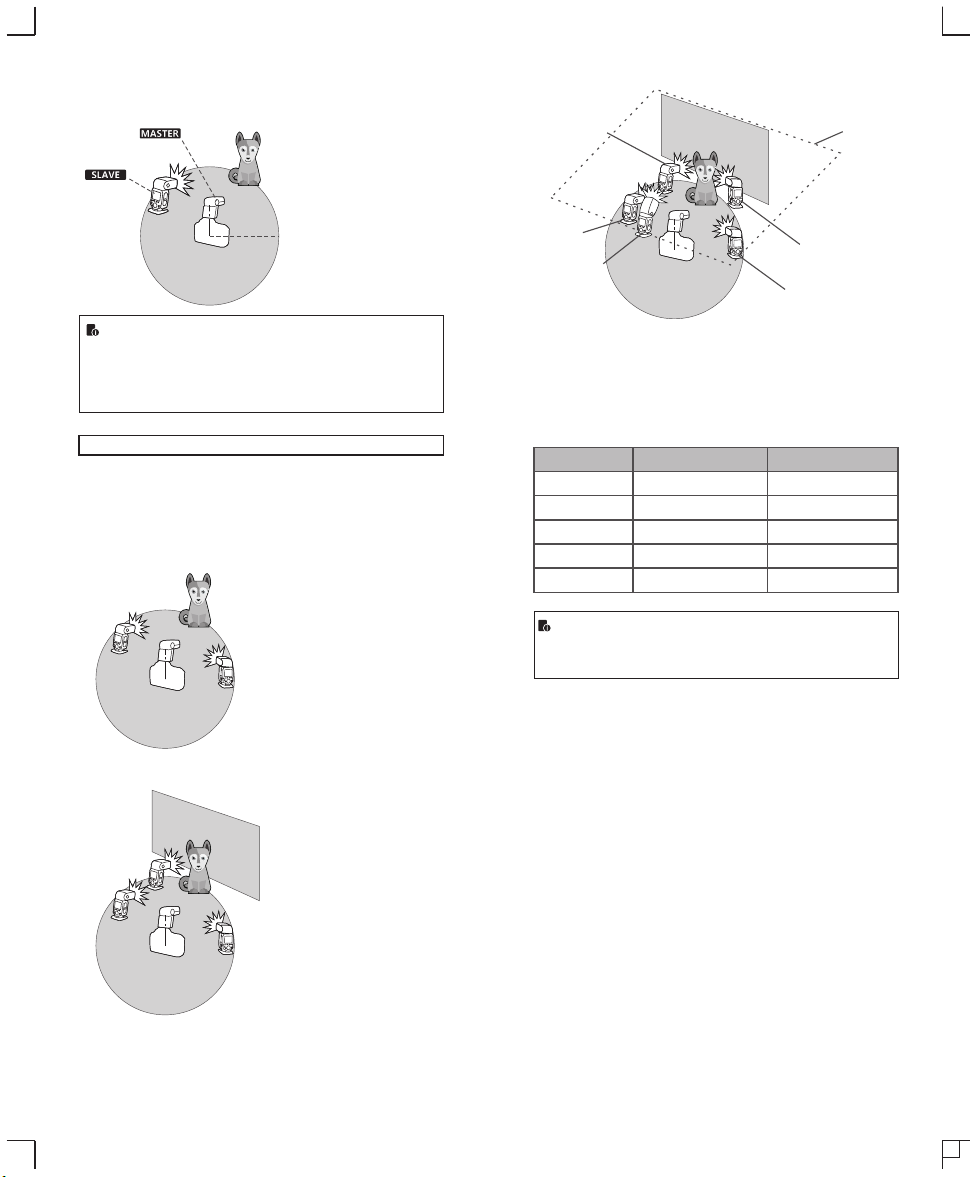
Positioning and Operation Range (Example of wireless flash
shooting)
● Autoflash Shooting with One Slave Unit
Transmission distance is about 100m.
● Shooting with a Different Flash Mode set for Each Group
Auto external
flash metering
E
E-TTL II
Manual flash
A
B
D
C
Manual flash
Manual flash
Ceiling
● Use the supplied mini stand to position the slave unit.
● Before shooting, perform a test flash and test shooting.
● The transmission distance might be shorter depending on
the conditions such as positioning of slave units, the
surrounding environment and whether conditions.
Wireless Multiple Flash Shooting
You can divide the slave units into two or three groups and perform
E-TTL II autoflash while changing the flash ratio (factor). In addition,
you can set and shoot with a different flash mode for each firing
group, for up to 5 groups.
● Auto Shooting with Two Slave Groups
A
B
● Auto Shooting with Three Slave Groups
C
A
* The flash mode settings are indicated only as an example
Wireless shooting using radio transmission has advantages over
wireless shooting using optic transmission, such as being less affected
by obstacles, and not having to point the slave unit’s wireless sensor
toward the master unit. The main functional differences are as follows:
Function
Distance
Channel
A/B/C Power
To be Disturbed
Group
Radio Transmission
100m
1~32
OFF, 1/128~1/1
Hard
A/B/C/D/E
Optic Transmission
15m
1~4
1/128~1/1
Easy
A/B/C
● There are four flash modes in this wireless radio transmission:
TTL, M, Multi and Gr. Choose one of those modes by pressing
the MODE Button.
- 57 -
B
- 58 -
Page 11

1. Wireless Settings
You can switch between normal flash and wireless flash. For normal
flash shooting, be sure to set the wireless setting to OFF.
Master Unit Setting
Press < > button so that < >
or < > are displayed on
the LCD panel.
Slave Unit Setting
Press < > button so that < >
or < > are displayed on
the LCD panel.
2. Master Unit’s Flash OFF
When the master unit is set to OFF, only the slave units will fire a
flash.
Press Function Button 4 so
1 that < > is displayed
2 < > to control the
< >:The master unit flash
firing is ON.
< >:The master unit flash
firing is OFF.
● Even if the master unit
flash firing is disabled, it
still fires a preflash to
transmit wireless signals.
MENU2
on the LCD panel.
Press Function Button 1
ON/OFF
ON/OFF of the master unit.
3. Setting the Communication Channel
If there are other wireless flash systems nearby, you can change the
channel IDs to prevent signal interference. The channel IDs of the
master unit and the slave unit(s) must be set to the same.
Press Function Button 4 so
1 that < > is displayed
2 that < > is displayed
MENU3
on the LCD panel.
Press Function Button 1 so
CH
on the LCD panel. Turn the
Select Dial to choose a
channel ID from 1 to 4.
Press the <SET> button to
3 confirm.
4. ETTL:Fully Automatic Wireless Flash Shooting
Using Automatic Wireless Flash with a Single Slave Unit
Master Unit Setting
1
● Attach a V860IIC camera
flash on the camera and
set it as the master unit.
●X1T-C can also be used as
master unit. X1T-C can
control V860IIC's ZOOM
value when the ZOOM is
adjusted to auto (A) mode.
Slave Unit Setting
2
● Set the other camera flash
as the wireless slave Unit.
Check the communication
3 channel.
● If the master unit and slave
unit(s) are set to a different
channel, set them to the
same channel. (Page 60)
Position the camera and
4 flashes.
● Position the camera and
flashes as the picture
shows. (Page 57)
- 59 - - 60 -
Page 12
Set the master unit’s flash
5 mode to <ETTL>.
● Set the master unit’s flash
mode to <ETTL>.
● For shooting, <ETTL> will
automatically be set for the
slave unit.
● Set the master unit flash
firing as ON to fire a flash.
Check that the flash is
6 ready.
● Check that the master flash
ready indicator is lightened.
● When the slave flash ready
indicator is ready, the AFassist beam lighting area
will blinks at 1 second
intervals.
Check the flash operation.
7
● Press the master unit’s
Test Button < >.
● Then, the slave unit will
fire. If not, adjust the slave
unit’s angle toward the
master unit and distance
from the master unit.
Using Automatic Wireless Flash with Multiple Slave Units
When stronger flash output or
more convenient lighting operation
is needed, increase the number of
slave units and set it as a single
slave unit.
To add slave units, use the same
steps as setting “automatic
wireless flash with a single slave
unit”. Any flash group can be set
(A/B/C).
When the number of slave units is
increased and the master unit
flash firing is ON, automatic
control is implemented to make all
groups of flashes fire the same
flash output and ensure the total
flash output up is to standard
exposure.
● Press the depth-of-field preview button on the camera to fire a modeling
flash.
● If the slave unit’s auto power off function is workable, press the master
unit’s test button to power it on. Please note that test firing is unavailable
during the camera’s regular metering time.
● The effective time of slave auto power off is changeable. (C.Fn-Sv APOT
Page 77)
● By making some settings, the auto AF-assist transmitter will not blink after
the slave unit’s flash ready indicator is lightened. (C.Fn-AF Page 77)
Using Fully Automatic Wireless Flash
The FEC and other settings that set on the master unit will also be
appeared on the slave unit automatically. The slave unit does not
need any operation. Use the following settings to make wireless
flashes according to the same methods with normal flash shooting.
● Flash Exposure Compensation ( Page 51)
● Flash Exposure Bracketing ( Page 52)
● Flash Exposure Lock (Page 52)
● High-Speed Sync ( Page 53)
● Manual Flash (Page 54)
● Stroboscopic Flash (Page 55)
Use two or more master units. By preparing several cameras that
with master units flash attached, cameras can be changed in
shooting while keeping the same lighting source (slave unit).
FEB
SYNC
About Master Unit
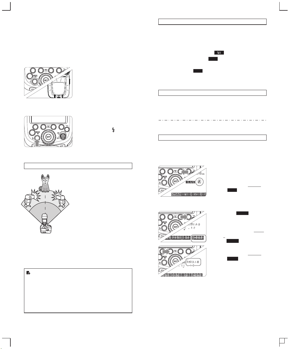
5.ETTL: Use the Wireless Shooting of Flash Ratio
Auto Flash Shooting with Two Slave Unit
Divide the slave units into A and B groups and balance their shooting
illumination (flash ratio).
Auto control exposure to make the total output of A and B flash
groups up to standard exposure.
Setting the flash groups of
1 slave unit.
● Set the flash as slave unit.
● Press Function Button 3
Gr
< > and choose
<A> or <B>.
● Set one slave unit as <A>,
the other as <B>.
MENU 2
Setting < >.
2
● Step 2 to Step 4 are set on
the master unit.
● Press the Function Button
4 on the master unit so that
MENU 2
< > is displayed.
Setting <RATIO A:B>.
3
● Press Function Button 2
RATIO
< > so that
<RATIO A:B> is displayed.
- 61 - - 62 -
Page 13
Setting flash ratio.
4
● Press Function Button 3
Gr
< >.
● Turn the Select Dial to set
the amount of flash ratio
and press<SET> button to
confirm.
Taking the picture.
5
● The slave units will flash
according to the flash ratio.
Auto Flash Shooting with Three Slave Unit
Setting the slave group
C
A
1 <C>.
B
2
● Use the same method of
step 1 (Page 62) to set the
slave unit of flash
group<C>.
Setting <RATIO A:B C>.
● Use the same method of
step 1 and step 3 (Page
62) to set the master unit
as <RATIO A:B C>.
Setting flash exposure
3 compensation.
● Use the same method of
step 1 (Page 62) to set the
slave unit of flash
group<C>.
● Press Function Button 2
< >. Turn the Select
Dial to set the amount of
flash exposure
compensation and
press<SET> button to
confirm.
About Slave Group Control
Slave Group A
ID=A ID=A ID=A
● When setting < RATIO A:B C >, group A, B and C will fire a
flash synchronously; when setting< RATIO A:B >, group C
will not fire a flash.
● If shooting under the situation that group C is toward the
main shooting subject, over exposure might occurred.
● In some EOS film cameras that support E-TTL autoflash,
you cannot perform multiple flash wireless shooting with a
flash ratio setting.
If three slave units are all set to
<A> in terms of slave ID, these
slave units will be controlled as if
they were one camera flash in
slave group A.
● The flash ratio of 8:1 to 1:1 to 1:8 is equivalent to 3:1 to 1:1
to 1:3 (1/2 step increment).
● The details of the flash ratio settings are as follows.
8:1 4 :1 2:1 1: 1 1:2 1:4 1 :8
5.6 :1 2.8: 1 1.4:1 1 :1.4 1: 2.8 1:5 .6
6. M: Wireless Flash Shooting with Manual Flash
This describes wireless (multiple shooting) using manual flash. You
can shoot with a different flash output setting for each slave unit
(firing group). Set all parameters on the master unit.
Setting the flash mode to
1 <M>.
Setting the number of flash
2 groups.
MENU1
● When < > is
displayed, press the
Function Button 2
RATIO
< > to set the
groups to fire.
● The setting changes as
follows each time you
press the button:
ALL(RATIO OFF)→
A/B(RATIO A:B)→
A/B/C(RATIO A:B:C)
Setting flash output.
3
● Press Function Button 3
Gr
< >. Turn the Select
Dial to set the flash output
of the groups. Press
<SET> button to confirm.
Taking the picture.
4
● Each group fires at the set
flash ratio.
● When ALL < RATIO OFF > is set, set A, B or C as the firing
group for the slave units.
● To fire multiple slave units with the same flash output,
select ALL < RATIO OFF > in step 2.
Setting <M> Flash Mode
You can directly operate the slave unit to manually set the manual
flash or stroboscopic flash.
Setting the slave unit.
1 (Page 59)
Setting flash mode to <M>.
2
● Press <MODE> button so
that <M> is displayed.
● Set the manual flash
output. (Page 54)
- 63 - - 64 -
Page 14

7. Multi: Wireless Flash Shooting with Manual Flash
Setting <MULTI> stroboscopic
flash.
● Press <MODE> button so that
<MULTI> is displayed.
● Setting the stroboscopic flash.
(Page 55)
8. Gr: Shooting with a Different Flash Mode for Each Group
When using an EOS digital camera released since 2012, such as
the EOS-1DX (except for EOS 1200D), you can shoot with a
different flash mode set for each firing group, with up to 5 groups
(A/B/C/D/E).
The flash mode that can be set are ①E-TTL II autoflash and
②Manual flash. When the flash mode is ①, exposure is controlled to
result in standard exposure for the main subject as a single group.
This function is for advanced users who are very knowledgeable and
experienced in lighting.
E
D
A
B
B
C
Set the flash mode to <Gr>
1 Press the <MODE> Button
and set the flash mode to
<Gr>.
Set the firing group of the
2 slave units
● Operate and set the slave
units one by one.
MENU1
● While < > is
displayed, press Function
Button 3 < > and
select <A>, <B>, <C>,<D>
or <E>.
● Set the firing group
(A/B/C/D/E) for all the
slave units.
Gr
Set the flash mode
3
● Set the flash mode of each
firing group by operating
the master unit.
● While < > is
displayed, press Function
Button 3 < > and
turn the Select Dial to
choose the group.
● Press Function Button 2
< > and select the
flash mode of the selected
group from <ETTL>, <M>
and <---(OFF)>.
● Repeat step 3 to set the
flash mode of all groups.
Set the flash output and
MENU1
Gr
MODE
4 flash exposure
compensation amount.
● While a firing group is
selected, press Function
Button 3 < >.
● Turn the Select Dial to set
the flash function
corresponding to flash
mode, and press <SET>
Button to confirm.
● When using the <M>
mode, set the flash output.
When using the <ETTL>
mode, set the flash
exposure compensation
amount as required.
● Repeat step 4 to set the
flash function of all groups.
● Press Function Button 4
< > to return to the
shooting-ready state.
Take the picture
5
● Each slave unit fires in the
respective flash modes set.
- 65 - - 66 -
Page 15

Wireless Flash Shooting: Optic Transmission
This product supports wireless flash application and functions
as either a master or a slave unit. As a master unit, it can control
Canon speedlites e.g. 580EXII, 600EX-RT via wireless. As a slave
unit, it can receive wireless signals of Canon speedlites e.g.
580EXII, 600EX-RT and commanders of Canon cameras e.g.
7D/60D/600D.
● You can set up two to three slave groups for E-TTL II autoflash
shooting. With E-TTL II autoflash, you can easily create various
lighting effects.
● Any flash settings (of flash exposure compensation, high-speed
sync, FE lock, FEB, manual flash, Multi flash) on the master unit
will be automatically sent to the slave units. So the only thing you
need to do is to set the master unit to ETTL mode without any
operation for the slave units at all during the shooting.
● This flash can work in ETTL autoflash, M manual flash, and Multi
stroboscopic flash modes when set as a master unit.
Positioning and Operation Range
Indoors
Outdoors
80°
8m(26.2ft) 12m(39.4ft)
● Even with multiple slave units, the master unit can control
all of them via wireless.
● In this user manual, “master unit” refers to the camera flash
on a camera and “slave unit” will be controlled by the
master unit.
15m(49.2ft)
10m(32.8ft)
1. Wireless Settings
You can switch between normal flash and wireless flash. For normal
flash shooting, be sure to set the wireless setting to OFF.
Master Unit Setting
Press < > button so that < >
or < > are displayed on
the LCD panel.
Slave Unit Setting
Press < > button so that < >
or < > are displayed on
the LCD panel.
2. Master Unit’s Flash OFF
When the master unit is set to OFF, only the slave units will fire a
flash.
Press Function Button 4 so
1 that < > is displayed
2 < > to control the
< >:The master unit flash
firing is ON.
< >:The master unit flash
firing is OFF.
MENU2
on the LCD panel.
Press Function Button 1
ON/OFF
ON/OFF of the master unit.
3. Setting the Communication Channel
If there are other wireless flash systems nearby, you can change the
channel IDs to prevent signal interference. The channel IDs of the
master unit and the slave unit(s) must be set to the same.
Press Function Button 4 so
1 that < > is displayed
2 that < > is displayed
MENU3
on the LCD panel.
Press Function Button 1 so
CH
on the LCD panel. Turn the
Select Dial to choose a
channel ID from 1 to 4.
Press the <SET> button to
3 confirm.
4. ETTL:Fully Automatic Wireless Flash Shooting
Using Automatic Wireless Flash with a Single Slave Unit
Master Unit Setting
1
● Attach a V860IIC camera
flash on the camera and
set it as the master unit.
●As a master unit, V860IIC
can control Canon
speedlites e.g. 580EXII,
600EX-RT via wireless.
- 67 - - 68 -
Page 16

Slave Unit Setting
2
● Set the other camera flash
as the wireless slave Unit.
● As a slave unit, V860IIC
can receive wireless signals
of Canon speedlites e.g.
580EXII, 600EX-RT and
commanders of Canon
cameras e.g. 7D/60D/600D.
Check the communication
3 channel.
● If the master unit and slave
unit(s) are set to a different
channel, set them to the
same channel. (Page 68)
Position the camera and
4 flashes.
● Position the camera and
flashes as the picture
shows. (Page 67)
Set the master unit’s flash
5 mode to <ETTL>.
● Set the master unit’s flash
mode to <ETTL>.
● For shooting, <ETTL> will
automatically be set for the
slave unit.
● Set the master unit flash
firing as ON to fire a flash.
Check that the flash is
6 ready.
● Check that the master flash
ready indicator is lightened.
● When the slave flash ready
indicator is ready, the AFassist beam lighting area
will blinks at 1 second
intervals.
Check the flash operation.
7
● Press the master unit’s
Test Button < >.
● Then, the slave unit will
fire. If not, adjust the slave
unit’s angle toward the
master unit and distance
from the master unit.
Using Automatic Wireless Flash with Multiple Slave Units
When stronger flash output or
more convenient lighting operation
is needed, increase the number of
slave units and set it as a single
slave unit.
To add slave units, use the same
steps as setting “automatic
wireless flash with a single slave
unit”. Any flash group can be set
(A/B/C).
When the number of slave units is
increased and the master unit
flash firing is ON, automatic
control is implemented to make all
groups of flashes fire the same
flash output and ensure the total
flash output up is to standard
exposure.
The slave unit might be out of order or fire an unwanted flash due to the
nearby fluorescent lamp or computer screen.
● Press the depth-of-field preview button on the camera to fire a modeling
flash.
● If the slave unit’s auto power off function is workable, press the master
unit’s test button to power it on. Please note that test firing is unavailable
during the camera’s regular metering time.
● The effective time of slave auto power off is changeable. (C.Fn-Sv APOT
Page 77)
● By making some settings, the auto AF-assist transmitter will not blink after
the slave unit’s flash ready indicator is lightened. (C.Fn-AF Page 77)
Using Fully Automatic Wireless Flash
The FEC and other settings that set on the master unit will also be
appeared on the slave unit automatically. The slave unit does not
need any operation. Use the following settings to make wireless
flashes according to the same methods with normal flash shooting.
● Flash Exposure Compensation ( Page 51)
● Flash Exposure Bracketing ( Page 52)
● Flash Exposure Lock (Page 52)
● High-Speed Sync ( Page 53)
● Manual Flash (Page 54)
● Stroboscopic Flash (Page 55)
Press Function Button 4 so that < >、< >和
FEB
< > are displayed.
FEB
SYNC
SYNC
About Master Unit
Use two or more master units. By preparing several cameras that
with master units flash attached, cameras can be changed in
shooting while keeping the same lighting source (slave unit).
- 69 - - 70 -
Page 17

5.ETTL: Use the Wireless Shooting of Flash Ratio
Auto Flash Shooting with Two Slave Unit
Divide the slave units into A and B groups and balance their shooting
illumination (flash ratio).
Auto control exposure to make the total output of A and B flash
groups up to standard exposure.
Setting the flash groups of
1 slave unit.
● Set the flash as slave unit.
● Press Function Button 3
Gr
< > and choose
<A> or <B>.
● Set one slave unit as <A>,
the other as <B>.
MENU 2
Setting < >.
2
● Step 2 to Step 4 are set on
the master unit.
● Press the Function Button
4 on the master unit so that
MENU 2
< > is displayed.
Setting <RATIO A:B>.
3
● Press Function Button 2
RATIO
< > so that
<RATIO A:B> is displayed.
Setting flash ratio.
4
● Press Function Button 3
Gr
< >.
● Turn the Select Dial to set
the amount of flash ratio
and press<SET> button to
confirm.
Taking the picture.
5
● The slave units will flash
according to the flash ratio.
Auto Flash Shooting with Three Slave Unit
Setting the slave group
C
A
1 <C>.
B
2
● Use the same method of
step 1 (Page 71) to set the
slave unit of flash
group<C>.
Setting <RATIO A:B C>.
● Use the same method of
step 1 and step 3 (Page
71) to set the master unit
as <RATIO A:B C>.
Setting flash exposure
3 compensation.
● Use the same method of
step 1 (Page 71) to set the
slave unit of flash
group<C>.
● Press Function Button 2
< >. Turn the Select
Dial to set the amount of
flash exposure
compensation and
press<SET> button to
confirm.
About Slave Group Control
Slave Group A
ID=A ID=A ID=A
● When setting < RATIO A:B C >, group A, B and C will fire a
flash synchronously; when setting< RATIO A:B >, group C
will not fire a flash.
● If shooting under the situation that group C is toward the
main shooting subject, over exposure might occurred.
● In some EOS film cameras that support E-TTL autoflash,
you cannot perform multiple flash wireless shooting with a
flash ratio setting.
If three slave units are all set to
<A> in terms of slave ID, these
slave units will be controlled as if
they were one camera flash in
slave group A.
● The flash ratio of 8:1 to 1:1 to 1:8 is equivalent to 3:1 to 1:1
to 1:3 (1/2 step increment).
● The details of the flash ratio settings are as follows.
8:1 4 :1 2:1 1: 1 1:2 1:4 1 :8
5.6 :1 2.8: 1 1.4:1 1 :1.4 1: 2.8 1:5 .6
6. M: Wireless Flash Shooting with Manual Flash
This describes wireless (multiple shooting) using manual flash. You
can shoot with a different flash output setting for each slave unit
(firing group). Set all parameters on the master unit.
Setting the flash mode to
1 <M>.
- 71 - - 72 -
Page 18

Setting the number of flash
2 groups.
MENU1
● When < > is
displayed, press the
Function Button 2
RATIO
< > to set the
groups to fire.
● The setting changes as
follows each time you
press the button:
ALL(RATIO OFF)→
A/B(RATIO A:B)→
A/B/C(RATIO A:B:C)
Setting flash output.
3
● Press Function Button 3
Gr
< >. Turn the Select
Dial to set the flash output
of the groups. Press
<SET> button to confirm.
Taking the picture.
4
● Each group fires at the set
flash ratio.
● When ALL < RATIO OFF > is set, set A, B or C as the firing
group for the slave units.
● To fire multiple slave units with the same flash output,
select ALL < RATIO OFF > in step 2.
Setting <M> Flash Mode
You can directly operate the slave unit to manually set the manual
flash or stroboscopic flash.
Setting the slave unit.
1
Setting flash mode to <M>.
2
● Press <MODE> button so
that <M> is displayed.
● Set the manual flash
output. (Page 54)
Other Applications
Wireless Control Function
The flash unit is built in with a Wireless Control Port so that you can
wirelessly adjust the power level of the flash and the flash triggering.
To control the flash wirelessly, you need a FT-16S
remote control set (on-camera and on-flash).
Insert its receive end into the Wireless Control
Port on the flash and insert the transmit end into
the camera hot shoe. Settings made on the
hotshoe-mounted transmit and receive ends
will be wirelessly communicated
to the flash. Then you can
press the camera shutter
release button to trigger
the flash. You can also hold
the transmit end at hand to
control your off-camera flash.
For full instructions on the use of FT series remote control, see its user
manual.
Sync Triggering
The Sync Cord Jack is a Φ2.5mm plug. Insert a trigger plug here
and the flash will be fired synchronously with the camera shutter.
Modeling Flash
If the camera has a depth-of-field preview button, pressing it will fire
the flash continuously for 1 second. This is called modeling flash.
It enables you to see the shadow effects on the subject and the
lighting balance. You can fire the modeling flash during wireless or
normal flash shooting.
● To avoid overheating and deteriorating the flash head, do
not fire the modeling flash for more than 10 consecutive
times. If you fire the modeling flash 10 consecutive times,
allow at least 10 minutes’ break for the camera flash.
● The modeling flash cannot be fired with the EOS 300 and
Type-B cameras.
7. Multi: Wireless Flash Shooting with Manual Flash
Setting <MULTI> stroboscopic
flash.
● Press <MODE> button so that
<MULTI> is displayed.
● Setting the stroboscopic flash.
(Page 55)
- 73 -
Auto Focus Assist Beam
In poorly-lit or low-contrast shooting environments, the built-in auto
focus assist beam will automatically light on to make it easier for
autofocus. The beam will light up only when autofocus is difficult
and get out as soon as the autofocus becomes correct.
If you want to turn off the auto focus assist beam, set the “AF” to
“OFF” on the C.Fn settings.
● If you find the auto focus assist beam does not light up, this
is because the camera has got a correct autofocus.
Position
Center
Periphery
Effective Range
0.6~10m / 2.0~32.8 feet
0.6~5m / 2.0~16.4 feet
- 74 -
Page 19
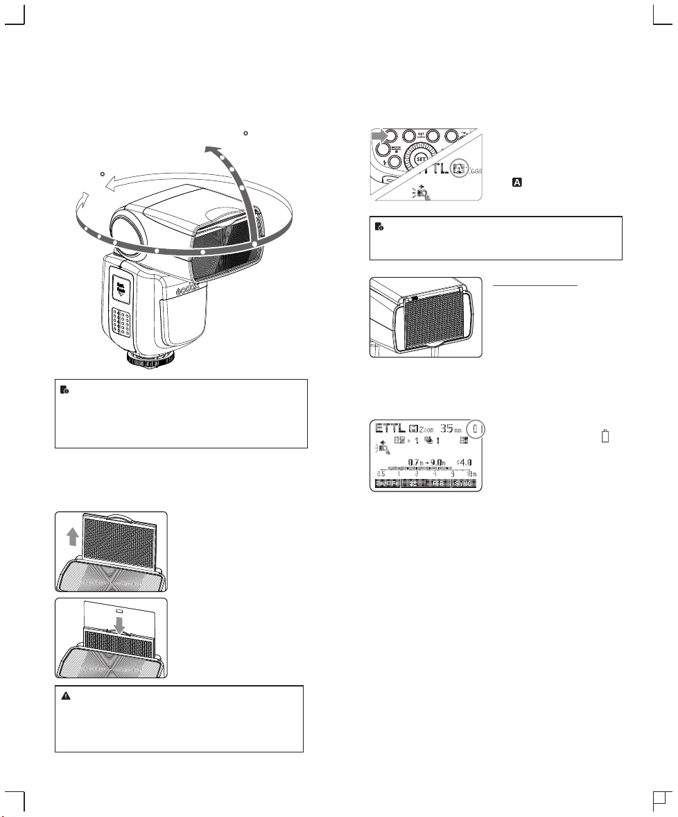
Bounce Flash
By pointing the flash head toward a wall or ceiling, the flash will
bounce off the surface before illuminating the subject. This can
soften shadows behind the subject for a more natural-looking shot.
This is called bounce flash.
To set the bounce direction, hold the flash head and turn it to a
satisfying angle.
-7-90
360
● If the wall or ceiling is too far away, the bounced flash might
be too weak and result in underexposure.
● The wall or ceiling should be a plain, white color for high
reflectance. If the bounce surface is not white, a color cast
may appear in the picture.
Creating a Catchlight
With the catchlight panel, you can create a catchlight in the subject’s
eyes to add life to the facial expression.
Point the flash head upward
1 by 90°.
Pull out the wide panel. The
2 catchlight panel will come out
at the same time.
ZOOM: Setting the Flash Coverage and Using
the Wide Panel
The flash coverage can be set automatically or manually. It can be
set to match the lens focal length from 20 mm to 200mm. Also, with
the built-in wide panel, the flash coverage can be expanded for
14mm wide-angle lenses.
In Manual Zoom mode, press the
<ZOOM/C.FN> button.
● Turn the Select Dial to change
the flash coverage.
● If < > is displayed, the flash
coverage will be set
automatically.
If you set the flash coverage manually, make sure it covers
the lens focal length so that the picture will not have a dark
periphery.
Using the Wide Panel
Pull out the wide panel and place it
over the flash head as shown. The
flash coverage will then be extended
to 14 mm.
● The catchlight panel will come out
at the same time. Push the
catchlight panel back in.
● The <ZOOM/C.FN> button will not
work.
Low Battery Warning
If the battery power is low, < >
will appear and blink on the LCD
panel. Please replace the battery
immediately.
Push the wide panel back in.
● Push in only the wide panel.
3
● Follow the same procedures
as for bounce flash.
● Point the flash head straight ahead and then upward by
90°. The catchlight will not appear if you swing the flash
head left or right.
● For best catchlight effect, stay 1.5m/4.9ft away from the
subject.
- 75 -
- 76 -
Page 20
C.Fn: Setting Custom Functions
Control with the Camera’s Menu Screen
The following table lists the available and unavailable custom
functions of this flash.
C.Fn Custom Functions
Custom
Function
Signs
m/ft
APO
FEB ACL
FEB
AF
Sv APOT
BEEP
LIGHT
LCD
Function
Distance indicator
Auto power off
FEB auto cancel
FEB order
AF-assist beam
Slave auto power
off timer
Beeper
Backlighting time
LCD contrast ratio
Setting
No.
m
ft
ON
OFF
ON
OFF
0 →− → +
- → 0 → +
ON
OFF
60min
30min
ON
OFF
12sec
OFF
ON
0~9
Settings &
Description
m
feet
ON
OFF
ON
OFF
ON
OFF
60min
30min
ON
OFF
Off in 12 sec.
Always off
Always lighting
10 levels
Custom
Functions
No.
C.Fn-00
C.Fn-01
C.Fn-03
C.Fn-04
C.Fn-08
C.Fn-10
C.Fn-20
C.Fn-22
1. Press <Zm/C.Fn> Backlight/Custom Setting Button for 2 seconds
or longer until C.Fn menu is displayed. The “Ver x.x” in the topright corner refers to the software version.
2. Select the Custom Function No.
● Turn the Select Dial to select the Custom Function No.
3. Change the Setting.
● Press<SET> button and the Setting No. blinks.
● Turn the Select Dial to set the desired number. Pressing <SET>
button will confirm the settings.
● After you set the Custom Function and press <MODE> button,
the camera will be ready to shoot.
4. In the C.Fn states, long press the “Clear”button for 2 seconds
until “OK”is displayed on the panel, which means the values in
C.Fn can be reset.
If the camera flash is attached to an EOS camera which has a
speedlite control function, the flash can be controlled using the
camera’s menu screen. For the menu operation procedure, refer to
your camera’s instruction manual.
Setting Camera Flash Functions ●
The following flash functions are settable according to different
flash modes.
1. Flash mode
2. Shutter sync (1st/2nd curtain, high speed sync)
3. FEB
4. Flash exposure compensation
5. Flash firing
6. Clear camera flash’s settings
Custom Functions of Camera Flash●
C.Fn-00, C.Fn-01, C.Fn-03, C.Fn-04, C.Fn-08, C.Fn-10, C.Fn-20,
and C.Fn-22.
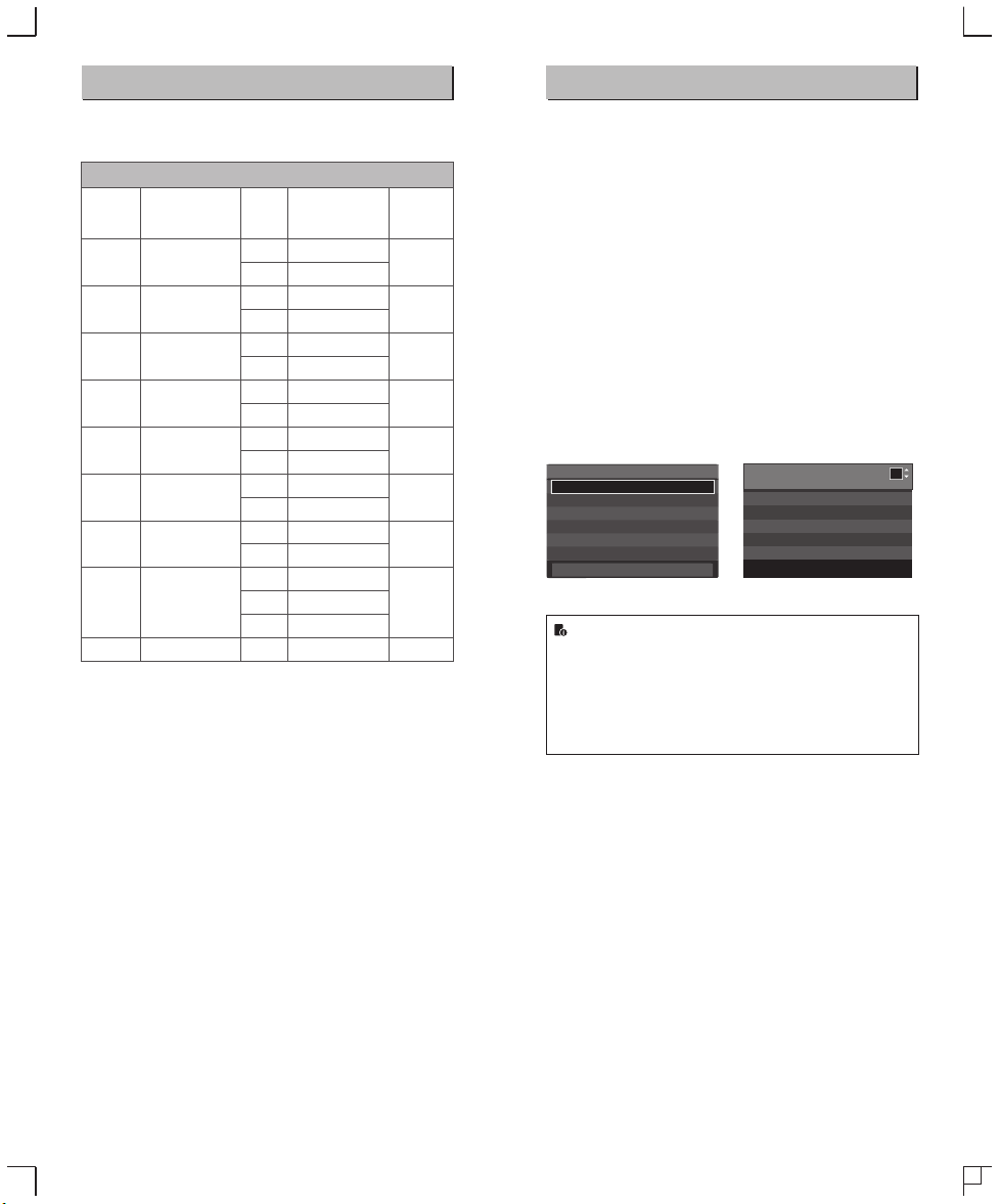
Clear All Flash Custom Functions
Flash function settings screen Flash C.Fn settings screen
Fla sh funct ion set tings
Fla sh mode
Shutter syne.
FEB
Flash exp. comp
E-TTL II
Flash firing
Clear Sp eedlite Settings
E-TTL II
1st curtain
-3.2.1.0.1.2.3
-3.2.1.0.1.2.3
Evaluative
Enable
-
-
Fla sh C.Fn s ettin gs
Aut o powe of f
0:E nable d
1:D isabl ed
-
0 1 2 3 4 5 6 7 8 9 10 11 12 13
0 0 0 0 0 0 0 0 0 0 0 0 0 0
* Screens from the EOS-1D Mark III.
● If flash exposure compensation has already been set with
the camera flash, flash exposure compensation cannot be
set with the camera. To set it with the camera, the camera
flash’s flash exposure compensation must be set to zero.
● If any Flash Custom Functions and flash settings other
than flash exposure compensation have been set by both
the camera and the flash, the latest settings will take effect.
1
- 77 -
- 78 -
Page 21

Page 22

Troubleshooting
Firmware Upgrade
If there is a problem, refer to this Troubleshooting Guide.
The Camera Flash does not fire.
● The camera flash is not attached securely to the camera.
→Attach the camera’s mounting foot securely to the camera.
● The electrical contacts of the Camera Flash and camera are dirty.
→Clean the contacts.
● < > or < > is not displayed in the view finder of camera.
→Wait until the flash is fully recycled and the flash ready indicator
lights up.
→If the flash ready indicator lights up, but < > or < > is not
displayed in the view finder, check whether this flash unit is
securely attached to the camera hotshoe.
→If the flash ready indicator does not light up after a long wait,
check whether the battery power is enough. If the battery power
is low, < > will appear and blink on the LCD panel. Please
replace the battery immediately.
The power turns off by itself.
● After 90 seconds of idle operation, auto power off took effect if the
flash is set as master.
→Press the shutter button halfway or press any flash button to
wake up.
● After 60 minutes (or 30 minutes) of idle operation, the flash unit
will enter sleep mode if it is set as slave.
→Press any flash button to wake up.
Auto zoom does not work.
● The camera flash is not attached securely to the camera.
→Attach the camera flash’s mounting foot to the camera.
The flash exposure is underexposed or overexposed.
● There was a highly reflective object (e.g. glass window) in the
picture.
→Use FE lock (FEL).
● You used high-speed sync.
→With high-speed sync, the effective flash range will be shorter.
Make sure the subject is within the effective flash range
displayed.
● You used Manual Flash mode.
→Set the flash mode to ETTL or modify the flash output.
Photos have dark corners or only parts of the target subject
are illuminated.
● The focal length of lens exceeds the flash coverage.
→Check the flash coverage you set. This flash unit has the flash
coverage between 20 and 200mm, which fits medium-format
cameras. Pull the wide panel out to extend the flash coverage.
This flash supports firmware upgrade through the USB port. Update
information will be released on our official website.
USB connection line is not included in this product. The USB
port is a standard Micro USB socket. Common USB
connection line is applicable.
Compatible Camera Models
This flash unit can be used on the following
Canon EOS series camera models:
5D Mark III 5D Mark II
1DX
650D 600D 550D 500D 450D
This table only lists the tested camera models, not all Canon
EOS series cameras. For the compatibility of other camera
models, a self-test is recommended.
Rights to modify this table are retained.
6D7D60D 50D 40D
400D Digital
30D
1100D 1000D
Maintenance
● Shut down the device immediately should abnormal operation be
detected.
● Avoid sudden impacts and the product should be dedusted
regularly.
● It is normal for the flash tube to be warm when in use. Avoid
continuous flashes if unnecessary.
● Maintenance of the flash must be performed by our authorized
maintenance department which can provide original accessories.
● This product, except consumables e.g. flash tube, is supported
with a one-year warranty.
● Unauthorized service will void the warranty.
● If the product had failures or was wetted, do not use it until it is
repaired by professionals.
● Changes made to the specifications or designs may not be
reflected in this manual.
- 81 - - 82 -
 Loading...