

Page 1
Publication: GP/291
Issue 4, January 2016
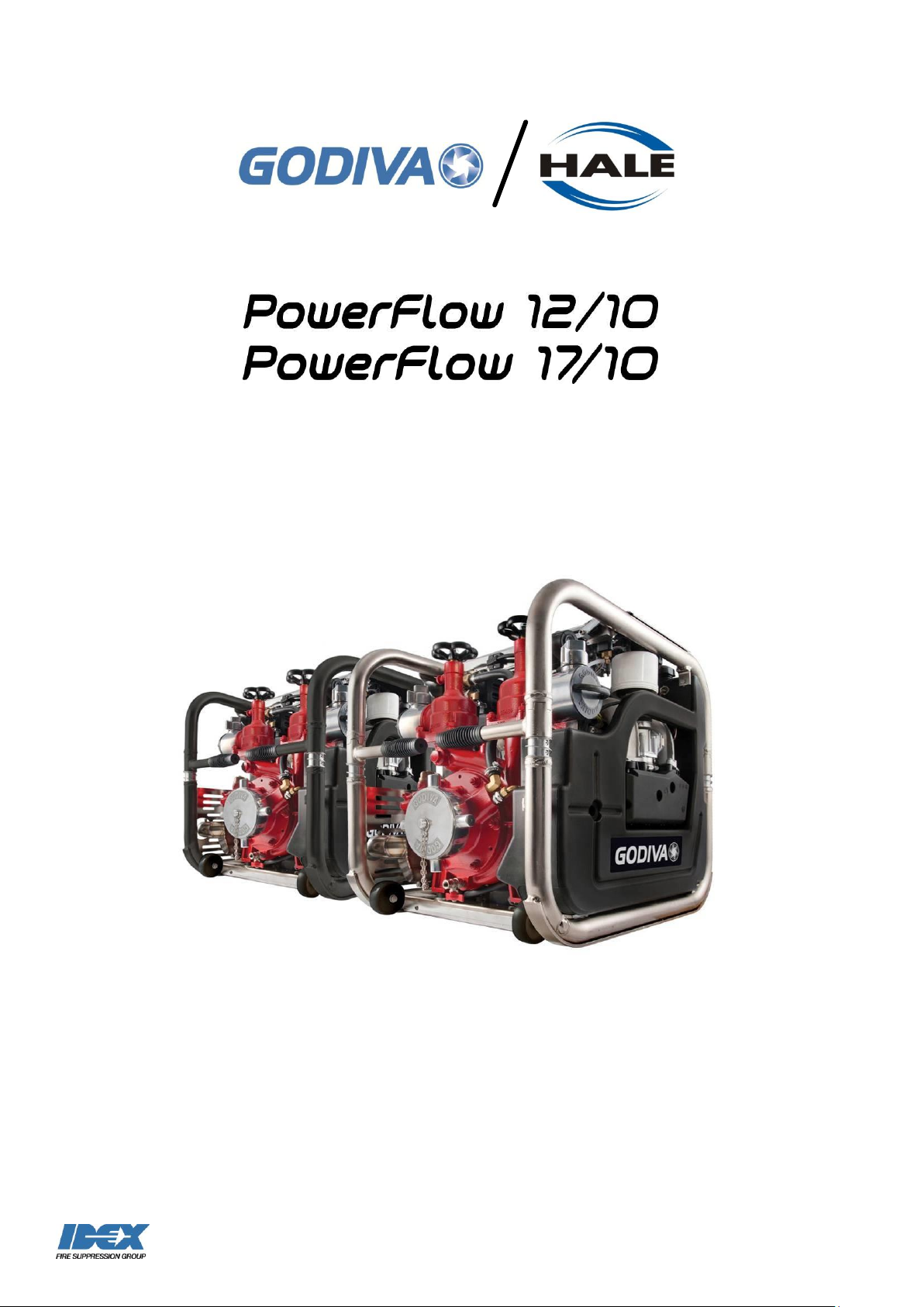
Portable Fire Pump
Workshop Manual
Page 2
1
©Godiva Ltd. Our policy is one of continuous development. We therefore reserve the
right to amend specifications without notice or obligation.
AMENDMENT RECORD
Model: 12/10, 17/10 Portable Fire Pumps
Mod
No.
Date
Page/s
Amendment
New Issue No.
1
May
2012
All
New publication
1 2 November
2012
8, 18-19
Revised oil level check procedure
2 3 April
2013
77
Addition of Adhesives, Solvents and
Greases List
3
4
January
2016
35, 63
Impeller nut – torque figure of 45Nm
specified
4
Page 3
2
©Godiva Ltd. Our policy is one of continuous development. We therefore reserve the
right to amend specifications without notice or obligation.
CONTENTS
AMENDMENT RECORD ............................................................................................... 1
CONTENTS ................................................................................................................... 2
IMPORTANT NOTES .................................................................................................... 5
SAFETY RELEVANT DATA .......................................................................................... 6
MAINTENANCE ......................................................................................................................... 6
TRAINING ................................................................................................................................ 6
SAFETY POINTS ....................................................................................................................... 6
ENVIRONMENTAL PROTECTION ................................ ................................ ............... 7
GENERAL DATA .......................................................................................................... 8
ENGINE ................................................................................................................................... 8
WEIGHT & MATERIALS .............................................................................................................. 8
CONSTRUCTION MATERIALS ..................................................................................................... 9
PUMP ...................................................................................................................................... 9
RECOMMENDED OPERATING PRESSURE ................................................................................. 10
OPTIONAL EQUIPMENT ........................................................................................................... 10
AUXILIARY SOCKET ................................................................................................................ 10
ASSOCIATED PUBLICATIONS ................................................................................................... 10
MAJOR COMPONENTS AND CONTROLS 17/10 AND 12/10 MODELS ................... 11
GENERAL ARRANGEMENT - LEFT HAND VIEW (FROM FRONT) .................................................... 11
GENERAL ARRANGEMENT - RIGHT HAND SIDE (FROM REAR)..................................................... 12
GENERAL ARRANGEMENT – CONTROLS AND INSTRUMENTS ...................................................... 13
ENGINE FLUIDS ......................................................................................................... 14
MAINTENANCE SCHEDULE ...................................................................................... 16
MAINTENANCE OPERATIONS .................................................................................. 17
Flush Pump ....................................................................................................................................... 17
Frost .................................................................................................................................................. 17
Engine Coolant Level ........................................................................................................................ 17
Coolant Change ................................................................................................................................ 18
Engine oil fill and level Check ........................................................................................................... 19
Change Engine Oil and Filter ............................................................................................................ 20
Engine Fuel Filter .............................................................................................................................. 21
Air Filter Element .............................................................................................................................. 21
Check and Adjust Valve play ............................................................................................................ 21
Sparking Plugs .................................................................................................................................. 22
Preparing the unit for storage ........................................................................................................... 22
PUMP TESTS ......................................................................................................................... 23
Running Test ..................................................................................................................................... 23
Vacuum Test - Exhaust Gas Priming ................................................................................................ 23
Pressure Test .................................................................................................................................... 23
BATTERY CARE ...................................................................................................................... 23
Safety ................................................................................................................................................ 23
Terminals .......................................................................................................................................... 24
Charging ............................................................................................................................................ 24
Gauges .............................................................................................................................................. 24
FAULT TRACING ........................................................................................................ 24
Page 4
3
©Godiva Ltd. Our policy is one of continuous development. We therefore reserve the
right to amend specifications without notice or obligation.
ENGINE ................................................................................................................................. 25
PUMP .................................................................................................................................... 25
PUMP LOG SHEET ..................................................................................................... 27
DATE .................................................................................................................................... 27
LOCATION ............................................................................................................................. 27
HOURS RUN ........................................................................................................................... 27
INSPECTION / FAULT ............................................................................................................... 27
PARTS USED .......................................................................................................................... 27
REASON FOR RENEWAL .......................................................................................................... 27
INITIALS ................................ ................................................................ ................................. 27
WORKSHOP MANUAL ............................................................................................... 28
REPAIR AND SPARE PARTS POLICY ......................................................................................... 28
RECOMMENDED SPARES ........................................................................................................ 29
REMOVAL & INSTALLATION .................................................................................... 30
INTRODUCTION ...................................................................................................................... 30
PRECAUTIONS ....................................................................................................................... 30
POST REPAIR AND ASSEMBLY ................................................................................................. 30
INSTALLATION ........................................................................................................................ 30
1. SUCTION TUBE – REMOVAL, WEAR RING, RE-ASSEMBLY ...................................................... 31
2. IMPELLER, MECHANICAL SEAL AND REAR WEAR RING .......................................................... 34
3. PRIMING VALVE .................................................................................................................. 35
4. PRIMING VALVE HEAT SHIELD ................................................................ ............................. 37
5. EXHAUST PRIMING SYSTEM ................................................................................................. 38
6. HEAT EXCHANGER ............................................................................................................. 44
7. OIL TANK ........................................................................................................................... 46
8. FUEL TANK ........................................................................................................................ 49
9. TO REMOVE PUMP BODY FROM THE ENGINE ......................................................................... 54
10. REPLACING PUMP ON TO ENGINE ...................................................................................... 55
11. PUMP ASSEMBLY ............................................................................................................. 56
12. RECOIL START ................................................................................................................. 65
13. DELIVERY VALVE .............................................................................................................. 72
14. INSTRUMENT PANEL ......................................................................................................... 74
15. ELECTRICAL SYSTEM ........................................................................................................ 74
16. ENGINE MAINTENANCE ..................................................................................................... 80
17. ADHESIVES, SOLVENTS AND GREASES LIST ....................................................................... 80
Page 5
4
©Godiva Ltd. Our policy is one of continuous development. We therefore reserve the
right to amend specifications without notice or obligation.
Page intentionally left blank.
Page 6
5
©Godiva Ltd. Our policy is one of continuous development. We therefore reserve the
right to amend specifications without notice or obligation.
!
IMPORTANT NOTES
Please read this manual before operating the machinery.
CRITICAL: Ex works, there is neither lubricating oil in the engine sump, nor electrolyte
in the battery. Refer to section:Error! Reference source not found..
Correct lubrication and maintenance is vital if satisfactory performance is to be
maintained.
Other than when priming, do NOT run the pump without water in the pump casing.
The terms ‘Left Hand’ (LH) and ‘Right Hand’ (RH) apply when the pump unit is viewed
from the suction tube end.
For specific engine information please refer to the Weber Operating and Maintenance
Instructions.
Fuel system Care
To ensure availability and reliability of gasoline powered units, please note the
following petrochemical industry guidelines:
Unleaded gasoline has a maximum shelf life of six months.
To avoid moisture in systems, keep fuel tanks FULL at all times.
Run engines up to normal operating temperature, pumping water, once every
two weeks.
Regarding fuel inhibitors, please consult the engine manufacturer.
Pump Serial Number
Pump Serial number ________________________
Specification GP12/10/___ Year manufactured _____
GP17/10/___ Year manufactured _____
The serial number, model specification and year of manufacture can be found on the
instrument panel on the top of the pump.
Page 7
6
©Godiva Ltd. Our policy is one of continuous development. We therefore reserve the
right to amend specifications without notice or obligation.
!
IMPORTANT
!
ATTENTION
SAFETY RELEVANT DATA
Thank you for purchasing a Godiva Pump.
Godiva Pumps are designed to give safe and reliable service.
BEFORE use, it is essential that the Operating and Installation Instructions are
carefully read and understood.
Maintenance
It is the responsibility of the user to ensure that the equipment is maintained in a safe
operational condition. Local legislative conditions may apply. UK only, Maintenance
(Regulation 5) of the Provision and Use of Work Equipment Regulations 1998 applies.
Training
It is ESSENTIAL that Godiva pumps are operated ONLY by TRAINED PERSONNEL.
Please contact Godiva Ltd to discuss your training needs.
To avoid damage and personal injury, operating procedures laid down in this document
MUST be observed.
Safety Points
Please read this manual before operating the machinery.
Safety notices -
= non-compliance could affect safety
= in case of damage to pump
= in case of personal hazards
The following points apply to pumps driven by petrol, diesel or other means:
The exhaust system becomes VERY HOT in use, DO NOT TOUCH. Allow the
system to cool before maintenance or inspection.
DO NOT OPERATE the unit close to flammable materials or structures.
ENSURE that exhaust fumes are safely ventilated.
DO NOT SMOKE while operating the unit.
DO NOT inhale fumes or gases.
Page 8
7
©Godiva Ltd. Our policy is one of continuous development. We therefore reserve the
right to amend specifications without notice or obligation.
DO NOT REFUEL unless the engine is stationary and COLD.
ENSURE that the fuel cap is secure and DO NOT overfill the tank.
Avoid prolonged skin contact with fluids, particularly if corrosive or carcinogenic.
When in use, keep ALL UNTRAINED people AWAY from the unit.
Where appropriate, eye protection should be worn.
DO NOT run the engine with the battery disconnected.
Disconnect the negative (-ve) battery lead first and reconnect last.
Isolate the electrical supply when working on the pump.
Avoid battery spillage.
Batteries produce EXPLOSIVE GASES, do not expose to sources of heat and
naked flames.
DO NOT lift heavy weights without assistance.
DO NOT remove protective guards or shields.
When cleaning the pump and engine use hot soapy water, do not use
flammable degreasers.
When cleaning the pump and engine use hot soapy water, do not use
flammable degreasers.
Noise
Operators must wear suitable EAR PROTECTION when the pump is running.
Gauges
Do not clean the glass surfaces of the gauges with abrasive or solvent cleaners. These
will cloud the glass surface. Use a mild detergent and water.
ENVIRONMENTAL PROTECTION
It is prohibited to pour engine oil and other contaminants onto the ground, down
sewers, drains, or into water courses.
Dispose of lubricants through authorised waste disposal contractors, licensed waste
disposal sites, or to the waste reclamation trade.
If in doubt, contact your Local Environmental Agency for advice regarding disposal
policies.
End of life disposal – please dispose of the pump according to local regulations relating
to recycling of materials.
Page 9
8
©Godiva Ltd. Our policy is one of continuous development. We therefore reserve the
right to amend specifications without notice or obligation.
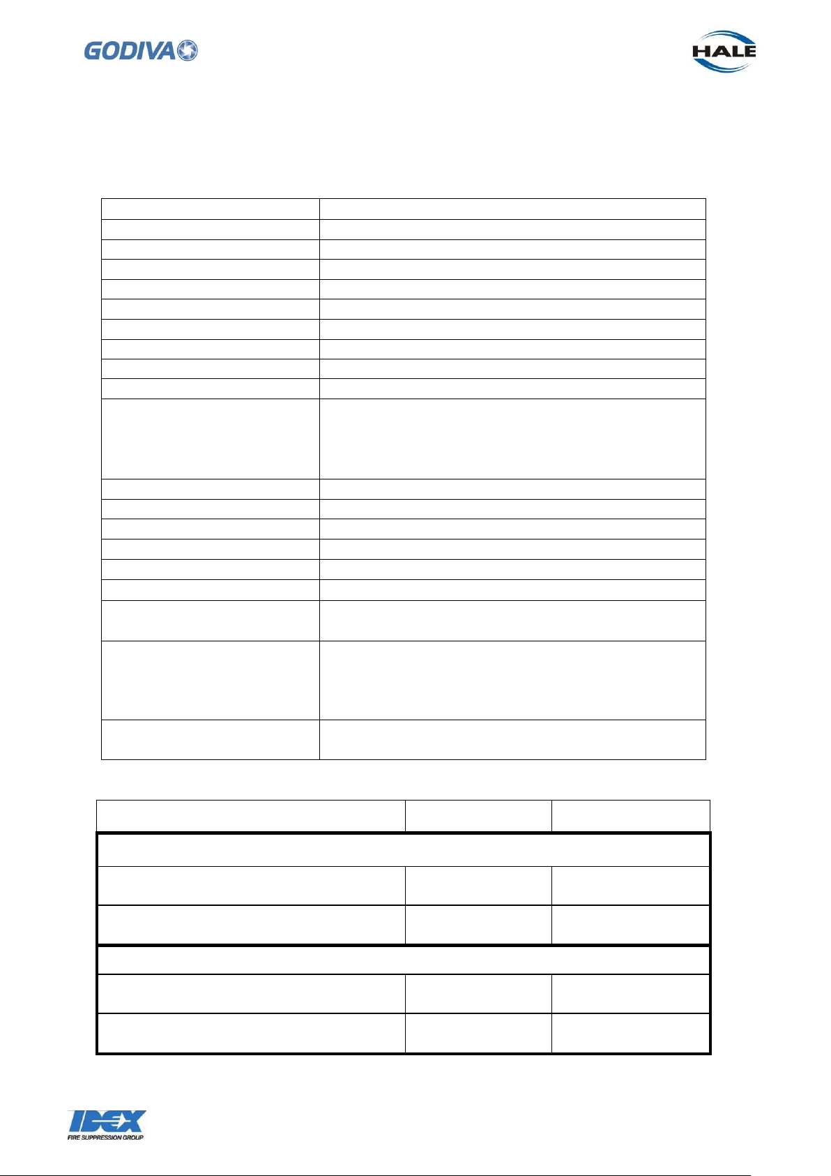
Engine type
Weber MPE 850 NA
Power 17/10 model
52 kW (70 HP) @ 7500 min-1 [rpm] ECE-R 85
12/10 model
40 kW (54 HP) @ 7500 min-1 [rpm] ECE-R 85
Capacity
846 cc
Number of Cylinders
2 cylinder
Valve Clearance - COLD
0.2 – 0.3mm Exhaust and Inlet
Ignition system
Electronically controlled
Spark Plug Gap
0.7 – 0.8mm
Spark Plug Type
Champion RC7 PYCB X
Lubrication
Pressurised Full Flow System
Service Oil Fill Capacity
2 litres 0W/40, synthetic, API SH, JASO MA.
Alternative 15W/50, only for operation under
ambient conditions > 0°C
Oil Filter
Metal spin on type
Fuel Type
Unleaded gasoline EU 95 RON, US 91 RON/MON
Fuel Feed
Electric pump
Fuel Capacity
18 litres
Run Time 17/10 model
60 minutes running at rated performance
12/10 model
75 minutes running at rated performance
Battery
12v, 19Ah Absorbent glass material type, no filling
required
Coolant
4 litres, ethylene glycol, silicate- and nitrite- free
Suitable for aluminium engines,50/50
water/coolant. Acts as anti-freeze in winter and
coolant in summer.
Manual start
12/10, 17/10 fitted with hand pulled recoil starter
Model 17/10
Model 12/10
Aluminium pump
Weight, dry
128Kg
125Kg
Weight, wet
148Kg
145Kg
Bronze pump
Weight, dry
160Kg
157Kg
Weight, wet
180Kg
177Kg
Engine
GENERAL DATA
Weight & Materials
Note: The wet weight is inclusive of the full capacity of engine oil, fuel, coolant and battery.
Page 10
9
©Godiva Ltd. Our policy is one of continuous development. We therefore reserve the
right to amend specifications without notice or obligation.
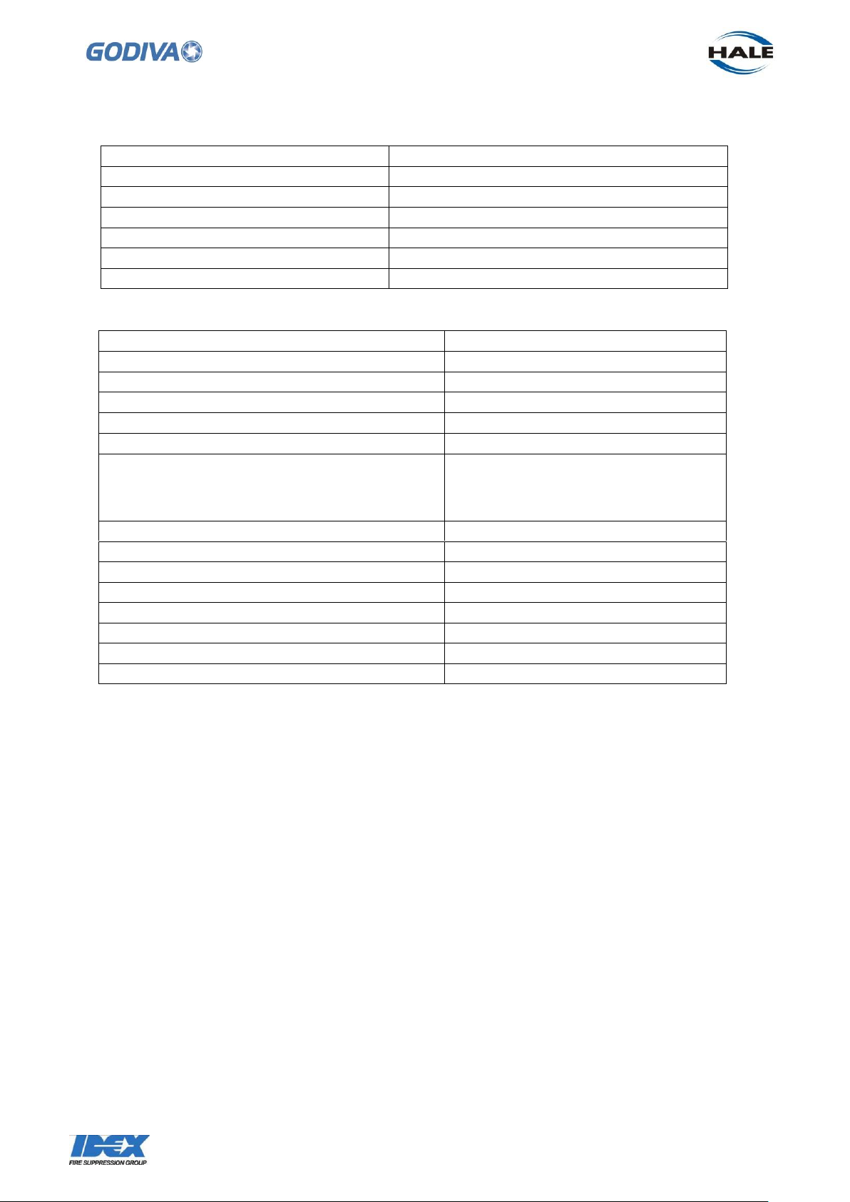
Pump Casing
Aluminium
Impeller
Aluminium
Pump shaft
Stainless steel
Wearing rings
Polyacetal
Cradle
12/10 Aluminium, 17/10 Stainless steel
Engine - Cylinder Head
Aluminium
Engine - Cylinder Block
Aluminium
Maximum output at 10 bar - 17/10
1700 l/min
12/10
1200 l/min
Rated output at 10 Bar - 17/10
1500 l/min – FPN 10-1500
12/10
1000 l/min – FPN 10-1000
Maximum Flow 17/10
2450 l/min at 3 bar
12/10
2150 l/min at 3 bar
Maximum Pump Discharge Pressure
17/10
12/10
17 bar (with boosted suction)
17 bar (with boosted suction)
Maximum Suction Inlet Pressure
10 bar
Priming time to 7.5m, 100mm suction lift
<30 seconds
Dimensions (L x W x H)
677 x 525 x 620 mm
Maximum angle of inclination
30° in any plane
Ambient operating temperature
-15° to 55°C in ambient air
45°C maximum for water in pump
Dangerous goods identification category
Class 9 UN3166
Construction Materials
Pump
Data source: Godiva 17/10, 12/10 light alloy pump with 4" suction; 2 x 2½" delivery
valve (typical connector configuration)
Page 11
10
©Godiva Ltd. Our policy is one of continuous development. We therefore reserve the
right to amend specifications without notice or obligation.
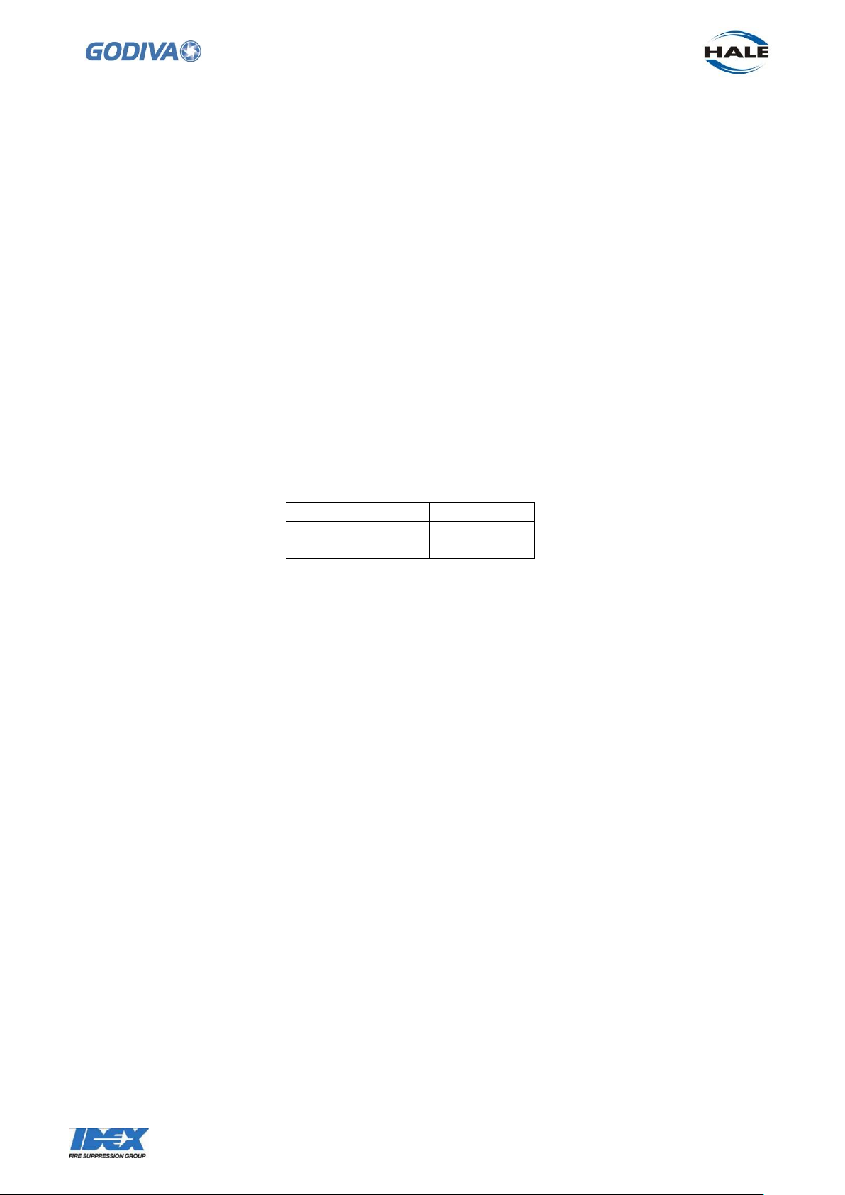
Publication
Part
Operation Manual
GP/282
Pump Parts List
GP/292
Recommended Operating Pressure
Maximum suction pressure 10 bar
Maximum delivery pressure 17 bar (when operating with boosted suction)
Operating beyond these parameters exceeds the limits of the pump specification, and
the pump could subsequently suffer damage.
Optional Equipment
Detachable floodlight – rated @ 55w.
Detachable wheel assembly for transporting pump over long distances.
Frame with extendable handles.
Additional fuel tank with quick release connection extension hose.
Auxiliary Socket
The 3-pin plug is provided for use with auxiliary equipment, e.g. floodlight or battery
charger. The plug is located on the right side of the pump just below the top of the
frame. Connect the plug to the equipment according to the equipment manufacturer’s
instructions.
Associated Publications
Page 12
11
©Godiva Ltd. Our policy is one of continuous development. We therefore reserve the
right to amend specifications without notice or obligation.
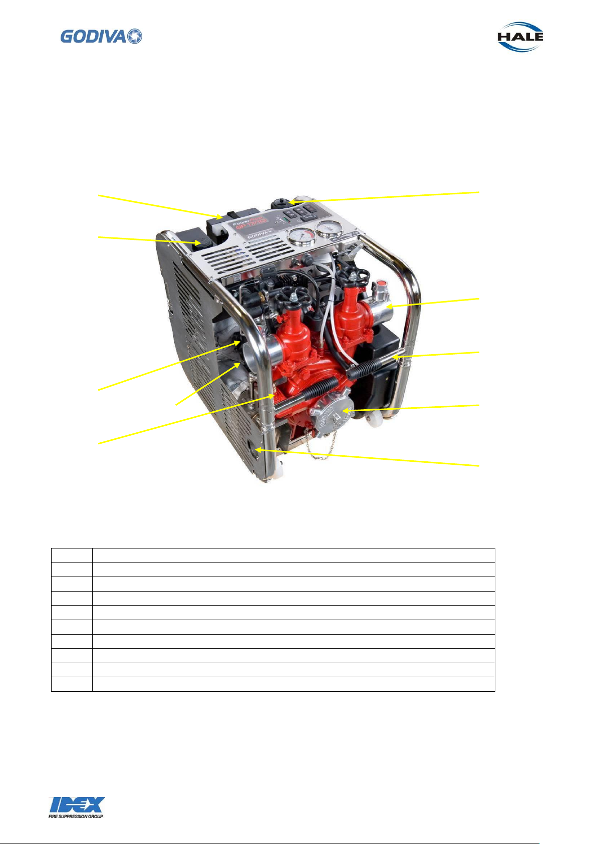
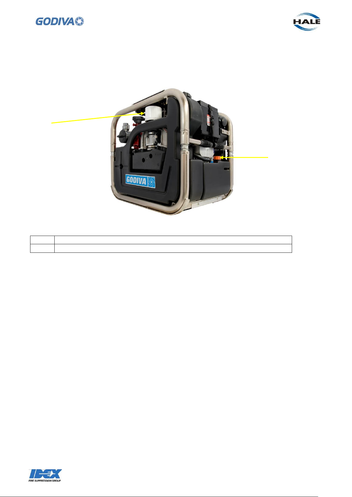
1
Priming valve – automatic operation
2
Engine oil filter
3
Coolant fill
4
Battery
5
Fuel filler cap
6
Delivery valve
7
Carrying handle – shown in stored position
8
Suction tube (shown with Round Thread connection)
9
Engine exhaust
10
Hand pulled recoil starter (behind volute)
6
4 5 8 1 2 7 9 3 10
MAJOR COMPONENTS AND CONTROLS
17/10 AND 12/10 MODELS
General Arrangement - Left Hand View (from front)
Page 13
12
©Godiva Ltd. Our policy is one of continuous development. We therefore reserve the
right to amend specifications without notice or obligation.
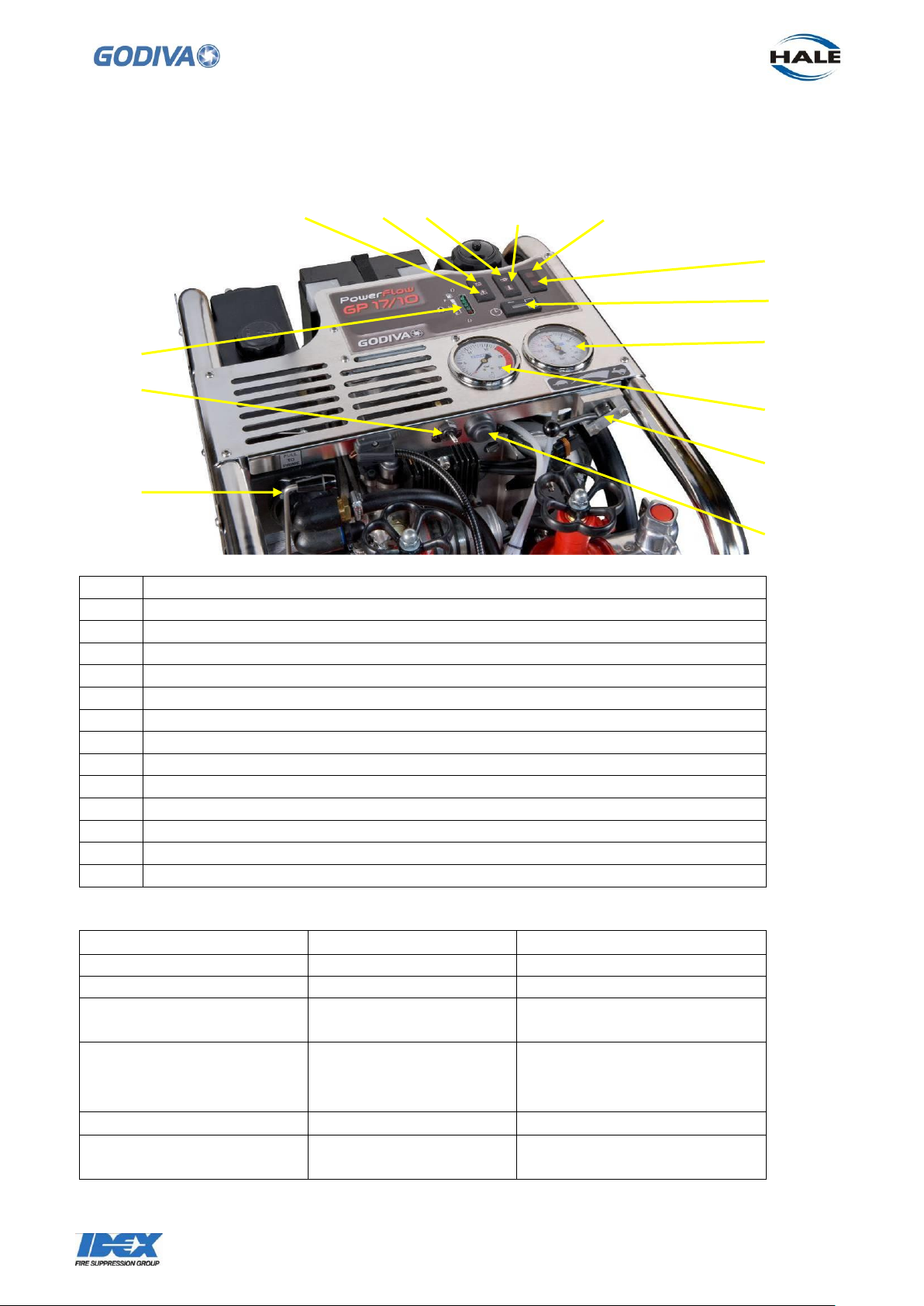
12
Air filter
13
Oil fill cap
12
13
General Arrangement - Right Hand Side (from rear)
Page 14
13
©Godiva Ltd. Our policy is one of continuous development. We therefore reserve the
right to amend specifications without notice or obligation.
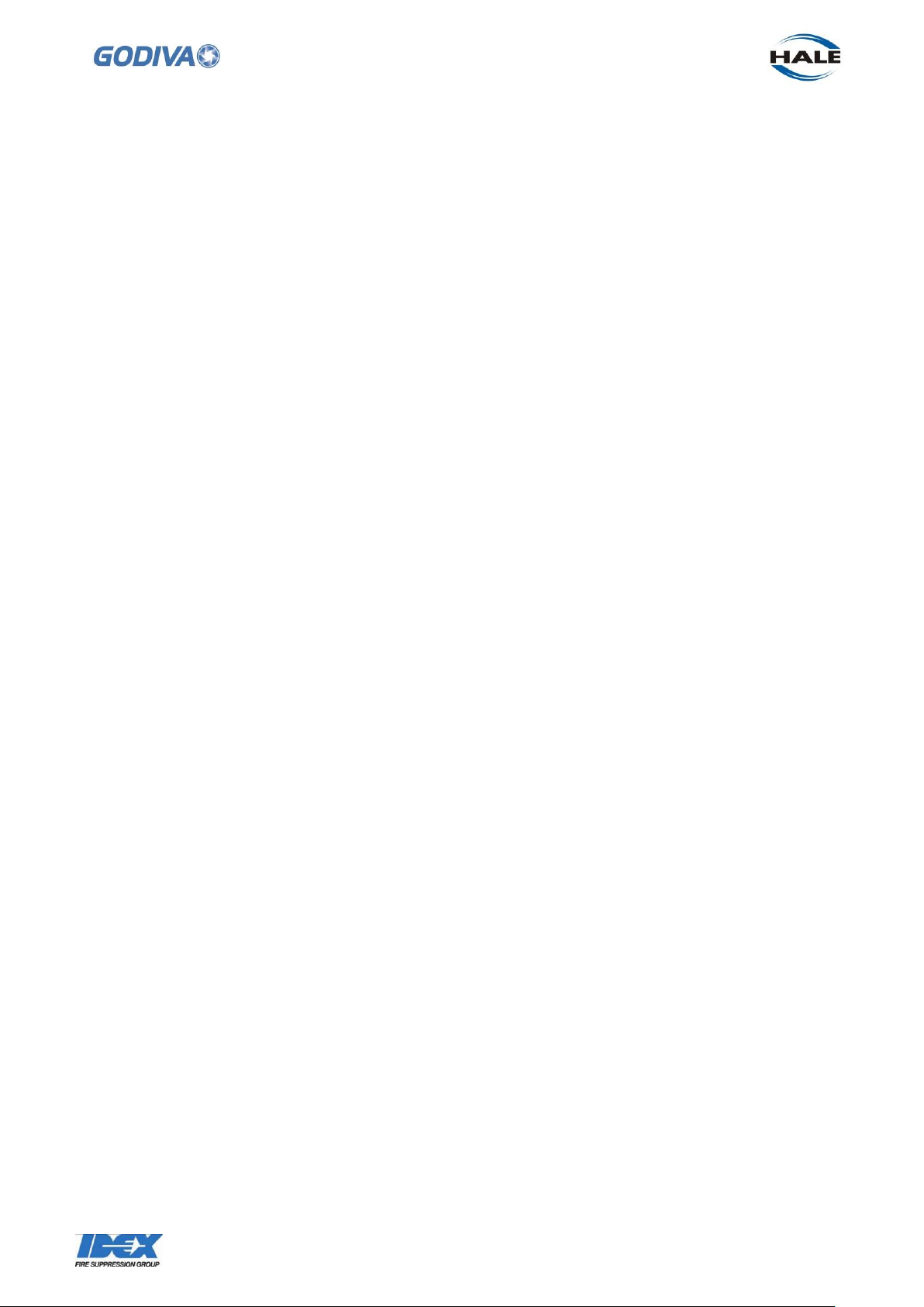
14
Priming lever
15
Engine on/off switch
16
Fuel level indicator
17
Malfunction indicator light
18
Battery warning light
19
Low oil pressure warning light
20
Coolant temperature warning light
21
Service Required (17/10 model only)
22
Not used
23
Hours run counter
24
Vacuum gauge (17/10 – 80mm dia. 12/10 – 60mm dia.)
25
Pressure gauge (17/10 – 80mm dia. 12/10 – 60mm dia.)
26
Throttle – controls pump speed
27
Engine start
Indicator
Meaning
Action
Fuel level
Shows fuel level
Refill at ¼ full tank
Hours run counter
Total hours run
For maintenance schedule
Low oil pressure
Engine oil pressure is
too low
Refer to workshop manual
Coolant temperature
Engine temperature too
high
Allow cold water to flow
through heat exchanger or
slow engine. Unblock filter.
Battery
Charge insufficient
Charge battery
Malfunction indicator lamp
Engine management
system fault identified
Refer to workshop manual
15
16
17
18
19
20
21
24
26
27
14
25
22
23
General Arrangement – Controls and instruments
Warning Lights
Page 15

14
©Godiva Ltd. Our policy is one of continuous development. We therefore reserve the
right to amend specifications without notice or obligation.
3 1 2
4
ENGINE FLUIDS
Also see Maintenance Operations, page 17, for procedures
1. Fuel Filling
Fill the fuel tank with 18 litres of unleaded gasoline.
EU 95 RON, US 91 RON/MON.
2. Coolant Filling
Fill the cooling system with a 4 litre mixture –
50 % water + 50 % coolant additive. Coolant additive based on ethylene glycol, silicate
and nitrite-free, suitable for aluminium engines.
Suitable additives BASF Glysantin G 30
Chevron Havoline Extended Life Coolant XLC+B
Valvoline Zerex G 30
The coolant acts as anti-freeze in the winter and coolant in the summer and must be
used all year round. Avoid splashing the coolant over the pump, it is a flammable
liquid.
3. Oil Filling
Fill the engine with 2 litres of oil.
0W/40, synthetic, API SH, JASO MA.
Alternative 15W/50, under ambient conditions > 0°C
4. Battery
Battery is the absorbant glass matt type. Supplied as a sealed unit.
Use a battery meter to check that the battery has retained a charge during transit and
storage, if necessary re-charge the battery until 12.4 volts are available.
Page 16
15
©Godiva Ltd. Our policy is one of continuous development. We therefore reserve the
right to amend specifications without notice or obligation.
Note: if the battery has been disconnected or removed from the unit, this
procedure must be followed to restart -
4.1 Reconnect the battery (red lead to positive terminal, black to negative terminal, in
that order).
4.2 Place throttle in closed position.
4.3 Turn on the engine, but do not press the starter.
4.4 Wait one minute - a click will be heard from the throttle body after precisely one
minute.
4.5 The unit is ready to be used.
Page 17
16
©Godiva Ltd. Our policy is one of continuous development. We therefore reserve the
right to amend specifications without notice or obligation.
Activity
Before
use
After
each
use
Every
Month
After
1st 25
hours
Every
100
hours
Every
200
hours
Every
3
years
Preparation
for storage4
Pump/
engine
Running test
Yes
Pump
Drain the
pump volute
Yes
Pump
Flush pump
with clean
water
Yes
Engine
Check oil
level
Yes1
Engine
Check
coolant level
Yes1
Engine
Change
engine oil
and oil filter
Yes2
Yes2
Yes
Engine
Check/clean
air filter
Yes2
Engine
Check and
adjust valve
play
Yes
Yes3
Engine
Replace
spark plugs
Yes3
Engine
Check spark
plugs
Yes
Engine
Change
coolant
Yes
Engine
Replace fuel
filter
Yes
Engine
Fuel
stabilizer
Yes
Engine
Internal
preservative
Yes
MAINTENANCE SCHEDULE
Note:
1 Or at least once a week
2 Or at least once a year if the specified hours of operation are not reached before that
3 Or at least every two years if the specified hours of operation are not reached before that
4 If the pump is not to be used for more than 30 days
Page 18

17
©Godiva Ltd. Our policy is one of continuous development. We therefore reserve the
right to amend specifications without notice or obligation.
Drain valve
Heat exchanger cross section,
as viewed from rear of pump
Fill coolant to this level
Internal tubing
Approximately 35mm
From top of filler cap
to surface of coolant
MAINTENANCE OPERATIONS
Using the maintenance schedule above, observe the following -
Flush Pump
Flush the pump thoroughly with clean water, especially after use with contaminated
water or seawater. Ensure the pump is drained.
Frost
If frost is expected, drain the pump volute by opening the drain valve, at the bottom of
the volute.
Engine Coolant Level
Fill the cooling system with a 4 litre approximate mixture, so that the coolant is just at
the side of the heat exchanger tubes inside the tank –
See page 14 for the list of suitable additives.
Page 19
18
©Godiva Ltd. Our policy is one of continuous development. We therefore reserve the
right to amend specifications without notice or obligation.
IMPORTANT
!
ATTENTION
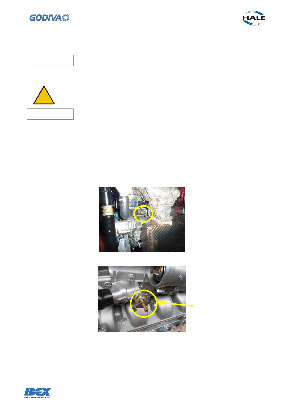
Attach drain hose
here
The coolant additive acts as anti-freeze in winter and coolant in summer and
must be used all year round.
Be careful when filling the cooling system not to let the coolant spill on to the exhaust
insulation below, the coolant is a flammable liquid.
Coolant Change
Coolant is drained through the drain tap at the lowest point in the system, which is
located on the left side of the engine. The drain tap fitted in this location is hidden
behind the side guard. Remove the side guard to access the drain tap. Connect a
suitable length of rubber hose to the drain tap, then turn the tap to drain the coolant.
Page 20
19
©Godiva Ltd. Our policy is one of continuous development. We therefore reserve the
right to amend specifications without notice or obligation.
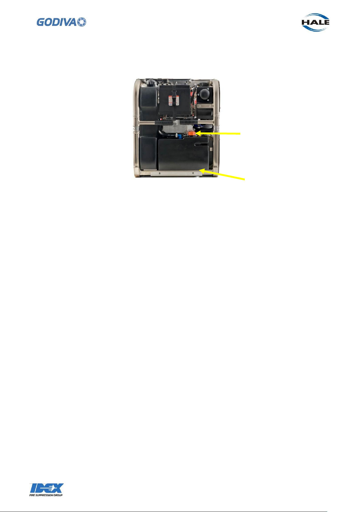
1. Oil tank cap/dipstick
2. Oil tank drain plug,
located under tank
Engine oil fill and level Check
For a new engine -
Fill the engine with 2 litres of oil, through the combined oil tank cap/dipstick (1).
At this stage do not check the oil level on the dipstick, as this will not be a true
representation of the oil level.
This is a dry sump lubrication engine. Engine oil is pumped from the engine into the oil
tank while the engine is operating. When the engine is switched off, a portion of the
engine oil may flow from the oil tank back into the engine. Run the engine at idle speed
for two minutes to circulate oil from the engine sump back into the oil tank (if possible
keep water in the pump to ensure the main seal is lubricated). Stop the engine and
check the oil level with the dipstick.
Remove the oil tank cap/dipstick (1), wipe the dipstick with a clean cloth, and re-insert.
Always screw the dipstick fully down to achieve a correct reading. Remove the dipstick
and note where the oil appears. The oil should now reach between the maximum and
minimum marks on the dip stick. Note: the minimum mark is the end of the dipstick. If
necessary top up the oil level or drain off some oil to achieve the correct level.
It is advisable to fill the engine in small quantities with repeat checking of the oil level to
ensure the correct amount is used. If excessive oil is indicated (above the maximum
mark on the dipstick) drain a small quantity of oil from the engine by using the drain
plug at the bottom of the oil tank (2), or by inserting an oil suction pump into the top of
the oil tank. In total 2 litres of oil should be used to fill a new engine.
Specification – 0W/40, completely synthetic, API SH.
Alternative oil is 15W/50 multi-grade but only for use in temperatures above 0°C.
Page 21
20
©Godiva Ltd. Our policy is one of continuous development. We therefore reserve the
right to amend specifications without notice or obligation.
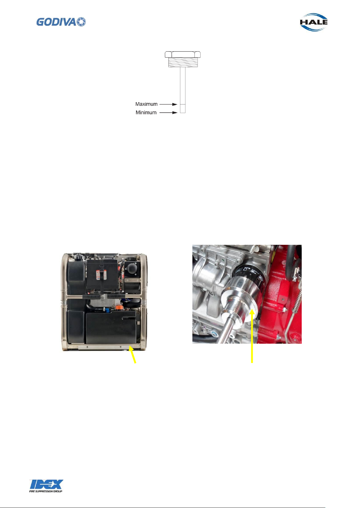
Oil tank drain plug
Located under tank
Special tool used to
remove the oil filter
For subsequent oil checks -
As stated before this is a dry sump lubrication engine. Oil is pumped from the engine
into the oil tank while the engine is operating. When the engine is switched off, a
portion of the engine oil may flow from the oil tank back into the engine. Therefore
inspect the oil level immediately after switching off the engine.
If the engine has been turned off, run the engine for two minutes at idle speed to
circulate oil from the engine sump back into the oil tank (if possible keep water in the
pump to ensure the main seal is lubricated). Stop the engine and check the oil level
with the dipstick as described in the previous section. If necessary top up the oil level
or drain off some oil to achieve the correct level.
Change Engine Oil and Filter
Engine oil is drained through the bottom of the oil tank. With the engine stationary and
oil still slightly warm, remove the plug and allow oil to drain into a suitable container.
Oil filter is located on the left side of the engine. Remove the guard, retained by 7
screws to the pump frame, to gain access to the oil filter. A special tool may be
required to undo the filter. Coat the seal of the new filter lightly with oil. Screw in the
new filter and hand tighten. Further information about changing the oil filter is provided
in the Weber Repair Manual section 110.04.01.
Page 22
21
©Godiva Ltd. Our policy is one of continuous development. We therefore reserve the
right to amend specifications without notice or obligation.
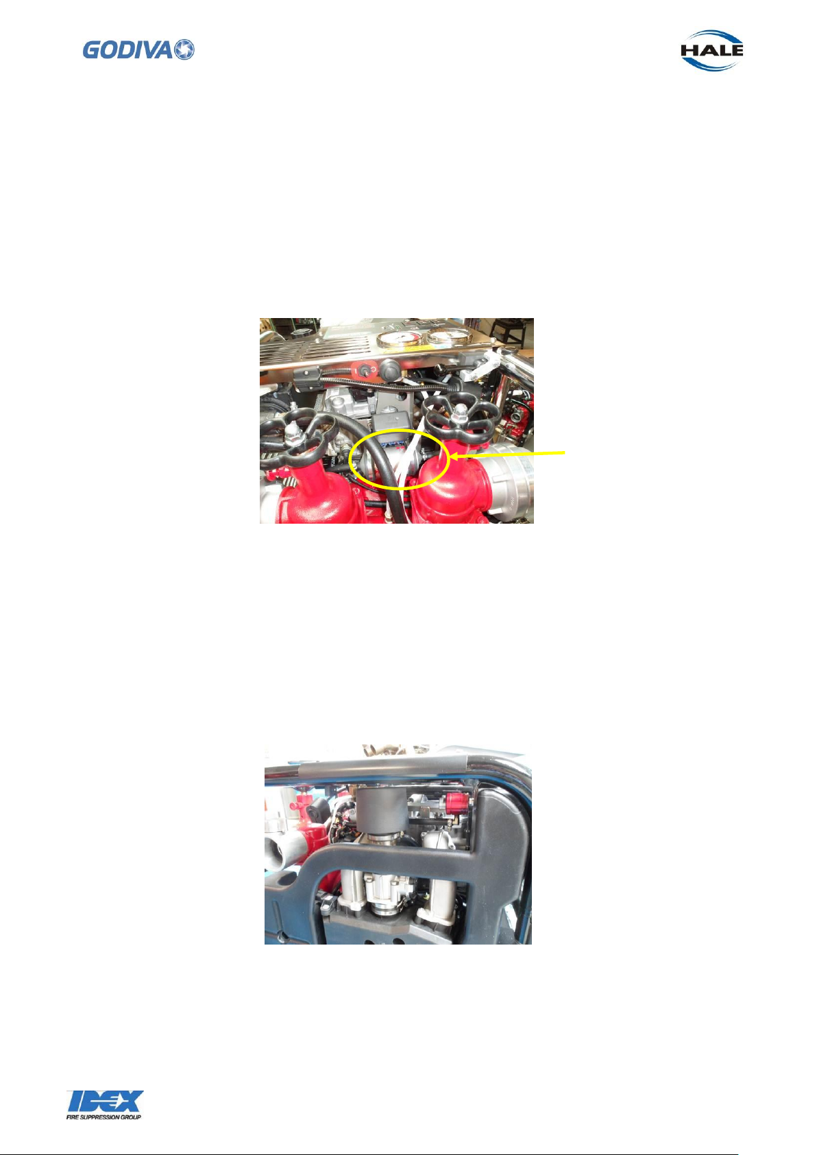
The fuel filter can be removed by disconnecting the hoses on both sides and
loosening the two clips holding the filter to the engine.
Location of fuel
filter on pump
Replace the drain plug and refill with oil through the top of the oil tank as described in
the Engine oil fill and level check section.
Engine Fuel Filter
Change the fuel filter
The fuel filter is located at the front of the pump behind the delivery valves and below
the fuse box.
Air Filter Element
The air filter is located on the right hand side of the pump. The filter and the plastic
cover are one unit. Remove the filter from the engine by undoing the clip at the filter
base. It may be necessary to remove the instrument panel on top of the pump to allow
better access to the air filter.
Check and Adjust Valve play
This procedure is described in the Weber Service Manual, Section 8.4.
Page 23
22
©Godiva Ltd. Our policy is one of continuous development. We therefore reserve the
right to amend specifications without notice or obligation.
Sparking Plugs
This procedure is described in the Weber Service Manual, Section 6.5.
Preparing the unit for storage
See Weber Service Manual, section 8.9
Change oil and oil filter
Add fuel stabiliser to the fuel tank
Check spark plugs
While spark plugs are removed, add preservative into cylinders
Replace spark plugs
Do not run the engine
Page 24
23
©Godiva Ltd. Our policy is one of continuous development. We therefore reserve the
right to amend specifications without notice or obligation.
!
Pump Tests
Running Test
Note: Valves, hoses and connectors may vary with customer specification.
To ensure the pump is kept in good condition and keep the battery charged, it is
recommended that the pump should be run once a month for 30 minutes.
1. Connect the pump to suction at a depth of between 1 metre and 3 metres.
2. Start and run the engine.
3. Prime the pump.
4. Open the delivery valve.
5. Run the pump at a pressure of 3 bar for approximately 30 minutes.
6. Stop the pump and drain volute.
Vacuum Test - Exhaust Gas Priming
Secure the suction tube blanking cap, close the delivery valve and open the manual
priming valve.
Start the engine, fully open the throttle and pull up the priming lever.
With a vacuum reading of 0.6 bar (18“hg) registering on the compound gauge, release
the priming lever and stop the engine. The vacuum reading must be maintained for a
minimum of 15 seconds. If vacuum retention fails, proceed to a pressure test to identify
the cause.
Should the pump be incapable of developing a vacuum of 0.6 bar, but hold whatever
vacuum it does develop, a fault in the priming system or gauge is indicated.
NOTE: Do not run the pump for more than 30 seconds when conducting this test or
damage may occur to the pump gland seal components.
Pressure Test
The purpose of this test is to trace a vacuum leak.
With the priming valve CLOSED, connect the pump to a water supply capable of
exerting a pressure of 3.5 / 7.0 bar (50 / 100 lbf / in2). This may be achieved either by
fitting an adaptor in the pump casing and then connecting this to a hose, or by using a
hydrant to suction tube adaptor.
To allow air to escape, partially open the delivery valve and apply water pressure. With
the pump casing full of water, close the delivery valve and build up the pressure to 3.5 /
7.0 bar (50 / 100 lbf / in2). If there are any leaks, their locations will be shown by the
seepage of water at those points.
Battery Care
Safety
The absorbent glass material (AGM) battery is a sealed unit and requires no fluid top
up during its life.
Page 25
24
©Godiva Ltd. Our policy is one of continuous development. We therefore reserve the
right to amend specifications without notice or obligation.
!
Terminals
Apply a thin film of petroleum jelly to both terminals and connectors.
Charging
Should charging become necessary, the input current (amps) must not be more than
10% of the battery rated capacity.
Gauges
Do not clean the glass surfaces of the gauges with abrasive or solvent cleaners. These
will cloud the glass surface, use a mild detergent and water.
FAULT TRACING
Engine
For specific engine related information, please refer to the Weber Service Manual
Safety
Rapid starter cord retraction (kickback) may pull your hand towards the engine.
Ensure that the fuel cap is secure.
Allow the engine to cool for at least two minutes before removing the fuel cap.
Check the fuel system regularly for cracks and leaks.
Do NOT crank the engine with the spark plug removed.
When tilting the engine, keep the spark plug side uppermost.
Page 26
25
©Godiva Ltd. Our policy is one of continuous development. We therefore reserve the
right to amend specifications without notice or obligation.
DEFECT
CAUSE
REMEDY
High vacuum gauge
reading / reduced lift
Suction strainers
blocked
Remove and clean
Failure to hold or lift
water
Suction hose joints
leaking.
Check and secure
Suction strainers not
completely
immersed.
Submerge
Leaking gland seal.
Pressure test and repair
as required
Delivery valve leak
Check and secure
Delivery jet uneven
Suction strainers not
completely
immersed.
Submerge
Leakage in suction
side
Check and secure joints
DEFECT
CAUSE
REMEDY
Engine will not start
No fuel
Add fuel
Engine Flooded
Allow excess fuel to
drain
Spark plug fouled
Check gap and adjust if
required
Renew spark plug
Engine rough
running or emitting
smoke
Fouled spark plug
Renew
Blocked, or oil
saturated air filter
Clean or renew as
required
Engine
Pump
In the event of the above information not leading to a solution, carry out the Monthly
pump tests for Pressure and Vacuum.
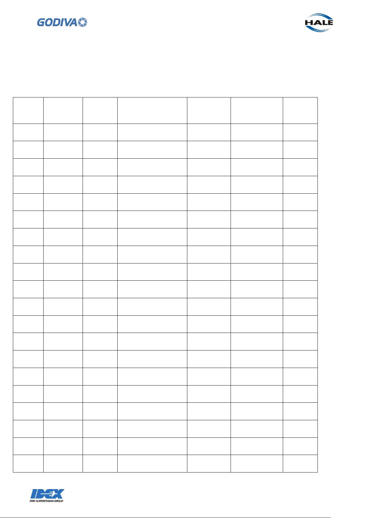
Use the following log sheet (or photocopy) to keep an historical record of your
maintenance and parts renewals, in accordance with the recommended maintenance
Page 27
26
©Godiva Ltd. Our policy is one of continuous development. We therefore reserve the
right to amend specifications without notice or obligation.
schedules of Godiva Ltd and Weber. This information may be useful should you need
to contact the manufacturer on any related matter.
Page 28
27
©Godiva Ltd. Our policy is one of continuous development. We therefore reserve the
right to amend specifications without notice or obligation.
Date
Location
Hours
run
Inspection / Fault
Parts
used
Reason for
renewal
Initials
PUMP LOG SHEET
Model __________ Serial No. ___________ Date Entered Service _______
Page 29

28
©Godiva Ltd. Our policy is one of continuous development. We therefore reserve the
right to amend specifications without notice or obligation.
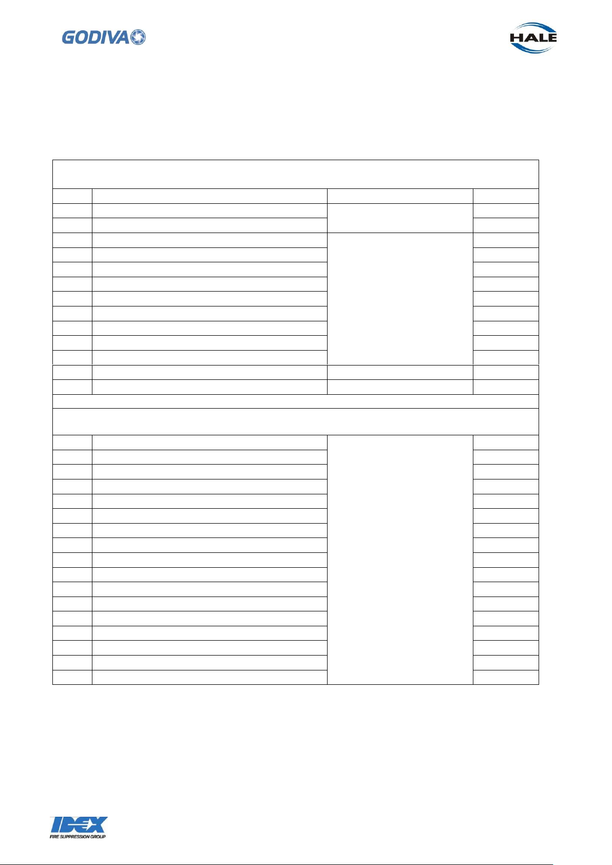
Model
Suction
Discharge
Starter
Primer
12/10
4inch RT
2 x 2½ Instantaneous
connection
Electric and
recoil handstart
Exhaust gas
prime
17/10
4inch RT
2 x 2½ Instantaneous
connection
Electric and
recoil handstart
Exhaust gas
prime
Other connector types, e.g.
Storz type are also covered by
this manual
WORKSHOP MANUAL
This section is relevant to the following pumps:
Repair and Spare Parts Policy
Pump
Godiva products may only be repaired or serviced by persons trained in said
procedures by either Godiva Ltd., or their approved agents.
Page 30
29
©Godiva Ltd. Our policy is one of continuous development. We therefore reserve the
right to amend specifications without notice or obligation.
Pump Spares Kit – Part Number 68230
Includes items 1-13
Item
Description
Location
Qty
1
Air filter assembly
Engine
2
2
Fuel filter
1
3
O ring, suction tube to volute
Pump
1
4
Wear ring
2
5
Nyloc nut, impeller to shaft
1
6
Impeller key
1
7
O ring, shaft to impeller
1
8
Mechanical seal
1
9
O ring, pump shaft to crankshaft
1
10
O ring, priming valve to volute
1
11
Dowty seal, strainer
2
12
Dowty seal, fuel drain plug
Fuel Tank
1
13
Sealing washer for oil drain
Oil Tank
2
Weber Engine Spares Kit – Part Number W105015
Includes items 1-17
1
Oil filter
Engine
4
2
Spark plug, RC7PYCBX
4
3
Sealing kit, valve cover
2
4
Serrated lock washer
6
5
Valve adjustment shim 2.85mm
1
6
Valve adjustment shim 2.90mm
1
7
Valve adjustment shim 2.95mm
1
8
Valve adjustment shim 3.00mm
1
9
Valve adjustment shim 3.05mm
1
10
Valve adjustment shim 3.10mm
1
11
Valve adjustment shim 3.15mm
1
12
Valve adjustment shim 3.20mm
1
13
Valve adjustment shim 3.25mm
1
14
Valve adjustment shim 3.30mm
1
15
Valve adjustment shim 3.35mm
1
16
Valve adjustment kit
1
17
Feeler gauges 0.05-2mm
1
Recommended Spares
The recommended two year spare parts inventory for the Godiva Powerflow 12/10,
17/10 Pump is listed below:
Page 31
30
©Godiva Ltd. Our policy is one of continuous development. We therefore reserve the
right to amend specifications without notice or obligation.
!
REMOVAL & INSTALLATION
Introduction
These instructions describe the complete strip-down of the pump. To reduce
unnecessary work and avoid the introduction of other issues, only dismantle those
parts necessary to effect inspection and or repair.
If replacement parts are needed, please refer to the Spare Manual (GP/292) for the
relevant assembly and part numbers.
Precautions
Before carrying out repair work, take the following precautions:
o Drain the fuel tank.
o Drain the engine oil tank.
o Drain the volute of water.
o Disconnect and remove the battery.
o Disconnect the electrical connections to the ignition coil.
Post Repair and Assembly
On completion of work:
o Refill ALL fluids, refit / reconnect battery and electrical leads.
o Carry out vacuum test.
o Complete the maintenance log.
Installation
Do NOT allow oil, grease or silicone products to contaminate Mechanical Seal mating
(ceramic / carbon) faces.
Page 32
31
©Godiva Ltd. Our policy is one of continuous development. We therefore reserve the
right to amend specifications without notice or obligation.
1. Suction Tube – Removal, Wear Ring, Re-assembly
The suction tube is the first component to be removed to allow access to the volute,
impeller and mechanical seal behind.
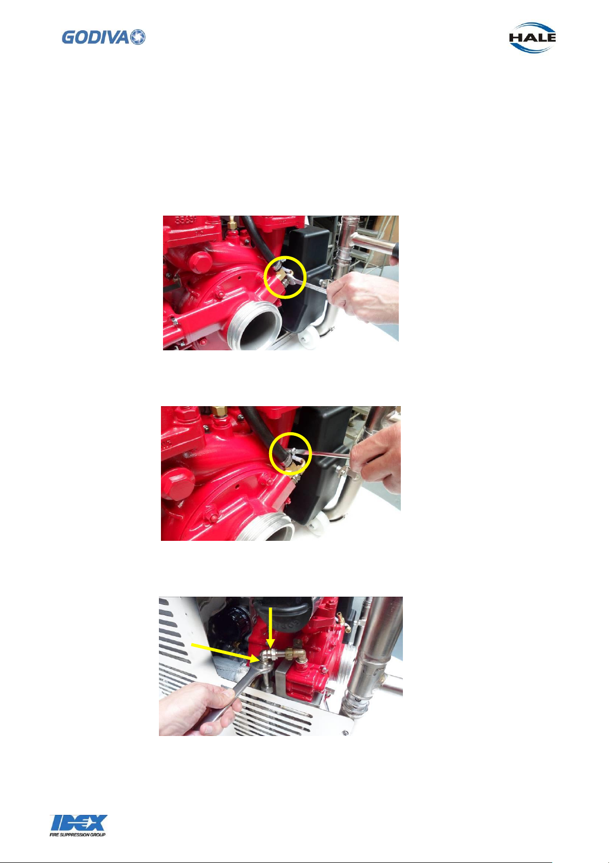
1.1 Disconnect the compound gauge tubing from the top of the suction tube, 16mm
spanner.
1.2 Disconnect rubber hose from heat exchanger to suction tube at the suction tube
end.
1.3 Loosen the unions on the priming pipe to allow the priming valve to separate from
the exhaust gas primer.
1.4 Remove the 6 x M8 nuts and washers retaining the suction tube to pump volute.
Use a 13mm socket and extension bar.
Page 33
32
©Godiva Ltd. Our policy is one of continuous development. We therefore reserve the
right to amend specifications without notice or obligation.
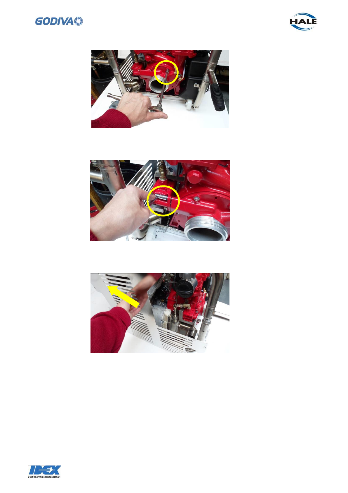
1.5 The priming valve must be loosened from its fixings to allow the suction tube to
come forward.
1.6 Remove the panel on the left hand side to gain better access to the priming valve Undo 7 x M6 socket head screws.
1.7 This will allow the priming valve to be removed completely from the suction tube.
Undo 2 x M6 bolts to remove the valve.
Be careful not to lose the O ring in the priming valve connecting port.
If necessary remove the guard plate, below and to rear of priming valve to allow full
access.
Page 34
33
©Godiva Ltd. Our policy is one of continuous development. We therefore reserve the
right to amend specifications without notice or obligation.
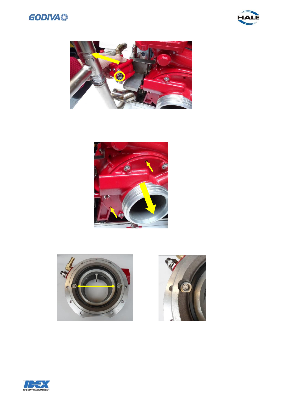
1.8 The suction tube can now be moved forward off the volute, use 3 x M8 screws to
pull off the suction tube by turning the screws evenly into the three holes on the face of
the suction tube .
1.9 The front wear ring (68026) can now be inspected for wear and damage.
Measure the ring across the internal diameter.
If the wear is more than 116.1 mm then replace the ring.
To remove the ring, undo 2 x M5 screws. When fitting the new ring apply a small
amount of threadlock – Loctite 243 or similar - to the screw threads. Tighten to 2Nm.
Page 35

34
©Godiva Ltd. Our policy is one of continuous development. We therefore reserve the
right to amend specifications without notice or obligation.
Seal face
Seal face
O ring
1.10 Reassembly
Reassembly of the suction tube is a reversal of the dismantling procedure. Check that
the large O ring is fitted to the rear of the suction tube, smear grease on to the O ring
to assist fitting back into the pump volute. Secure the suction tube with the 6 x M8 nuts.
When replacing the side panel apply a small amount of Loctite 243 to the 7 x M6
socket head screws retaining the panel to the frame..
2. Impeller, Mechanical Seal and Rear Wear Ring
With the suction tube removed the impeller, main shaft seal and the rear wear ring will
be accessible in this sequence –
2.1 Remove the M16 nyloc nut retaining the impeller onto the shaft.
Carefully move the impeller forward and away from the shaft.
Check the impeller for wear and damage, if necessary then replace.
Note: when refitting the impeller a new nyloc nut must be used.
2.2 The shaft seal is now exposed (mechanical type)
The seal is in two parts –
1. Spring loaded section inserted into the rear of the impeller
2. The mating section is fitted into the pump body
If either seal face is worn replace with a new seal. The seal face in the pump body will
require a sharp tool to dislodge it from the body. The seal faces can be cleaned with a
solvent cleaner, Loctite 7076 or equivalent.
Page 36

35
©Godiva Ltd. Our policy is one of continuous development. We therefore reserve the
right to amend specifications without notice or obligation.
Note: the O ring (57129) on the shaft, if this is worn – replace.
When replacing the seal, use an aerosol to spray clean water on both faces to lubricate
the seal action.
2.3 Check the rear wear ring (68026) for wear and damage
If the wear is more than 116.1mm then replace the ring (same as front wear ring)
To remove the ring, undo 2 x M5 screws. When fitting the new ring apply a small
amount of threadlock – Loctite 243 or similar - to the screw threads. Tighten to 2Nm.
2.4 While the impeller is removed from the pump, the front and rear wearing
dimensions can be checked. This dimension should be no less than 114mm.
This dimension must be measured on the front and back of the impeller.
2.5 When the shaft seal and wear ring inspections are completed the impeller can be
replaced. Make sure the impeller key is located on the shaft. There is a slot in the rear
of the impeller that aligns with this key. Apply grease to the end of the pump shaft.
Note: when refitting the impeller a new nyloc nut must be used. Tighten the impeller
nut to the shaft to a torque of 45 Nm. This will push the impeller back into position on
the shaft.
3. Priming valve
To inspect and repair the Priming Valve, remove the complete assembly as described
in sections 1.3 to 1.7.
Page 37
36
©Godiva Ltd. Our policy is one of continuous development. We therefore reserve the
right to amend specifications without notice or obligation.
Diaphragm to
check
Insert an 9mm
AF square bar
here to hold
piston, while
seal is undone
at the other side
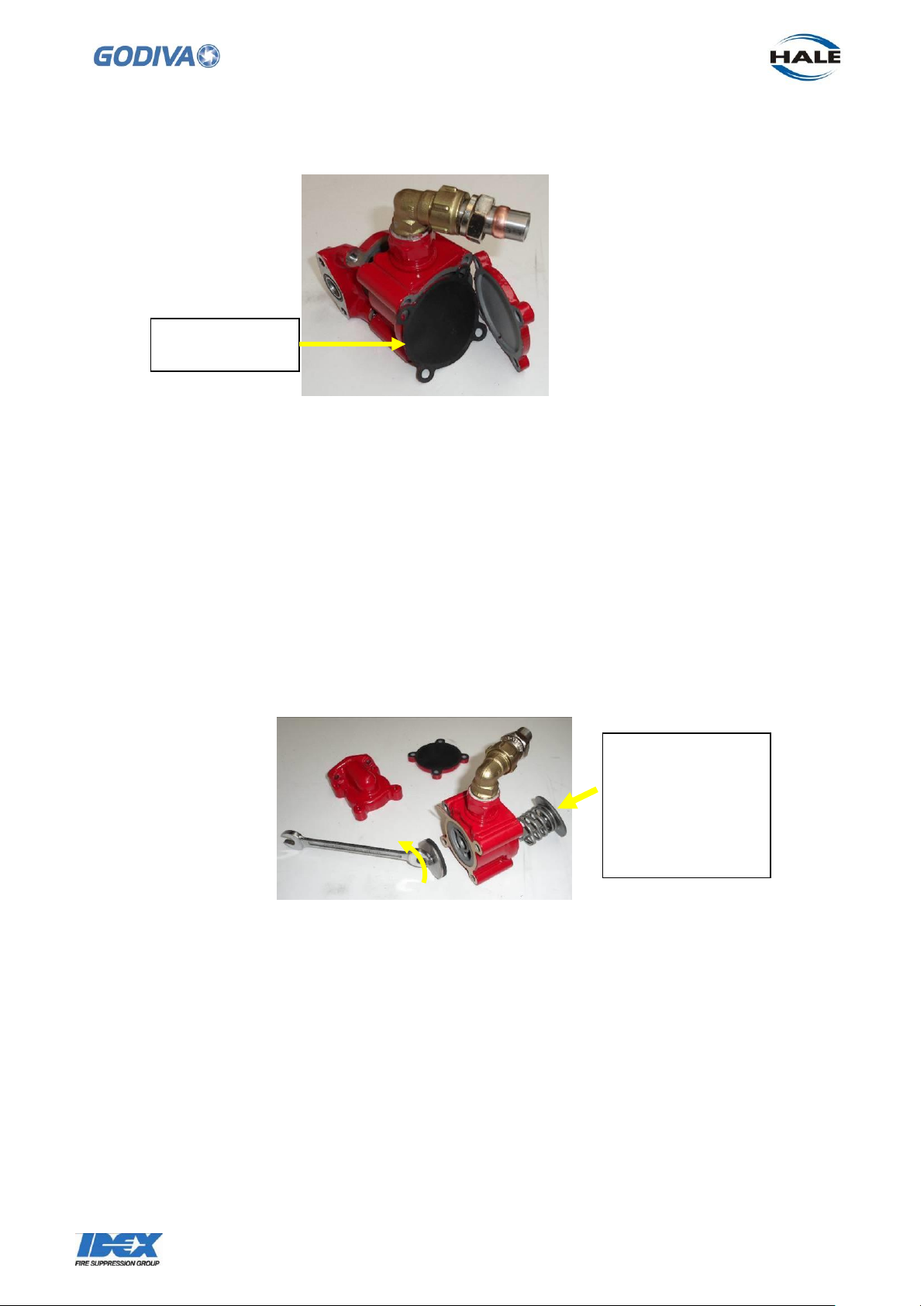
3.1 Undo the 4 x M6 bolts holding the back cover to the valve body
Behind the cover is the diaphragm (56123), inspect this for damage, if necessary
replace.
3.2 On the suction tube side of the valve, is the inlet housing (detaches from the valve
when the cover is removed)
The internal parts are a spring loaded piston connected through the centre of the valve
to a seal (seal is mounted on a backing plate with a retaining washer). Check the
condition of the seal (55669). If the seal is worn, replace it. The retaining washer must
be flat.
To release the seal, undo the M6 screw at the seal end, while preventing the assembly
from turning by inserting an 9mm AF square bar in the outer face of the piston.
3.3 Clean the internal areas of the valve before re-assembling.
Apply Loctite 243 to the screw (MS104/8) holding the piston to the seal retaining plate.
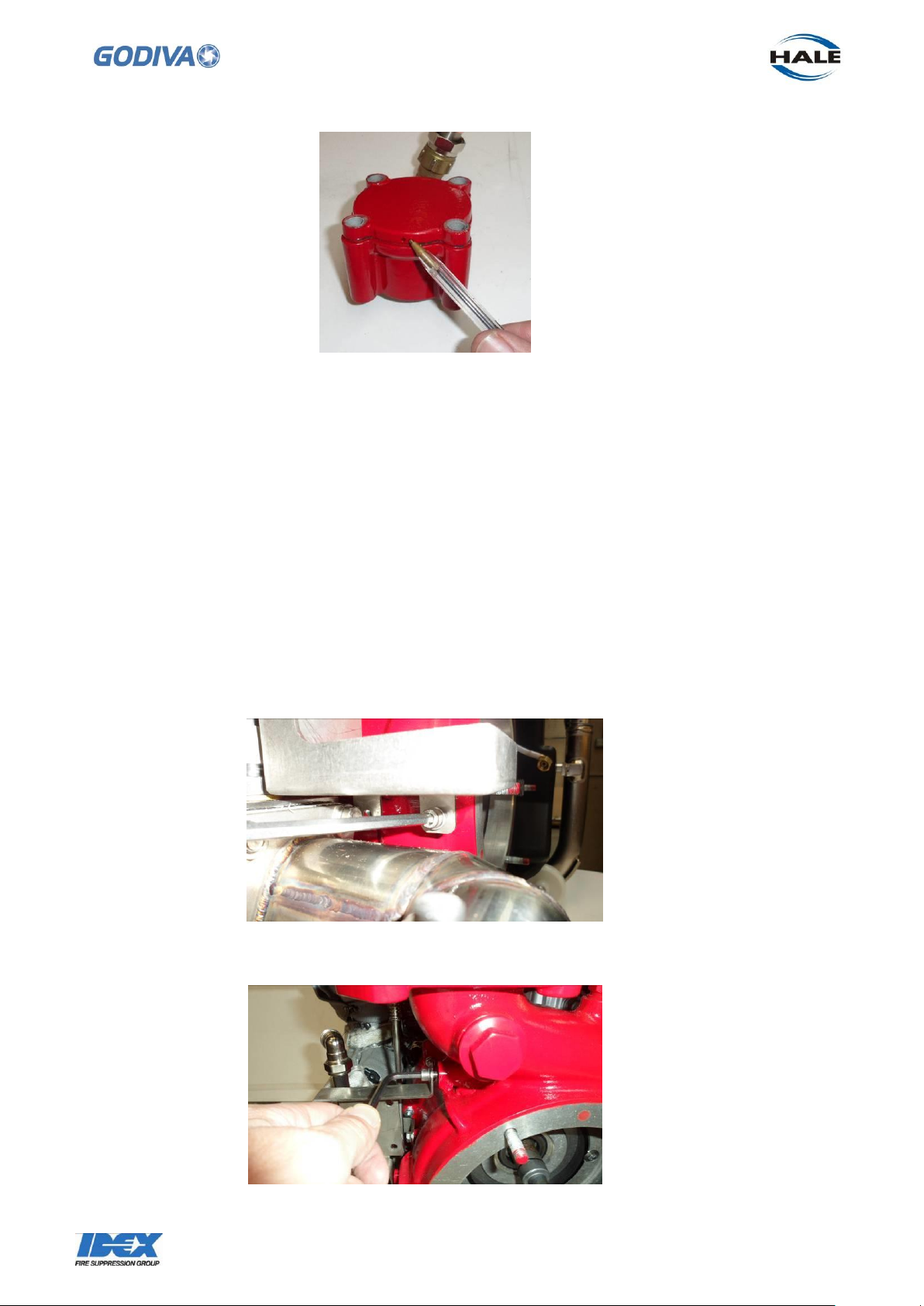
3.4 When replacing the cover, ensure the small air hole is facing downwards, this
allows the atmosphere to act on the diaphragm.
Page 38
37
©Godiva Ltd. Our policy is one of continuous development. We therefore reserve the
right to amend specifications without notice or obligation.
3.5 Replace the 4 x M6 bolts to the cover, the valve body and into the inlet on the other
side. The complete assembly can now be re-attached to the suction tube if necessary.
3.6 When the priming valve assembly is complete it can be re-attached to the suction
tube, if required at this stage, by reversing instructions in section 1.3 – 1.7
4. Priming Valve Heat Shield
When the priming valve is removed from the pump, the heat shield can also be
removed to allow better access to the exhaust priming assembly below.
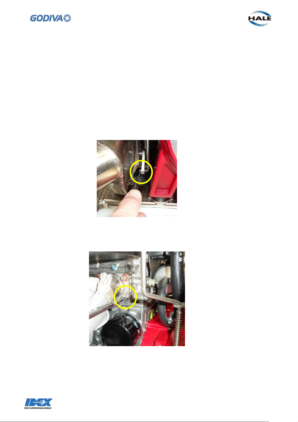
4.1 Undo the 3 x M6 screws retaining the guard to the side of the volute.
There are two screws below the guard and one at the top.
Undo the two screws below the shield.
4.2 Undo the top screw and the shield will come away from the pump.
Page 39
38
©Godiva Ltd. Our policy is one of continuous development. We therefore reserve the
right to amend specifications without notice or obligation.
5. Exhaust priming System
The exhaust priming system on the left side of the pump can be removed from the
engine for inspection and repair as necessary. Points to attend to are –
Exhaust priming mechanism
Heat insulation blanket (on manifold)
5.1 To remove the exhaust priming assembly.
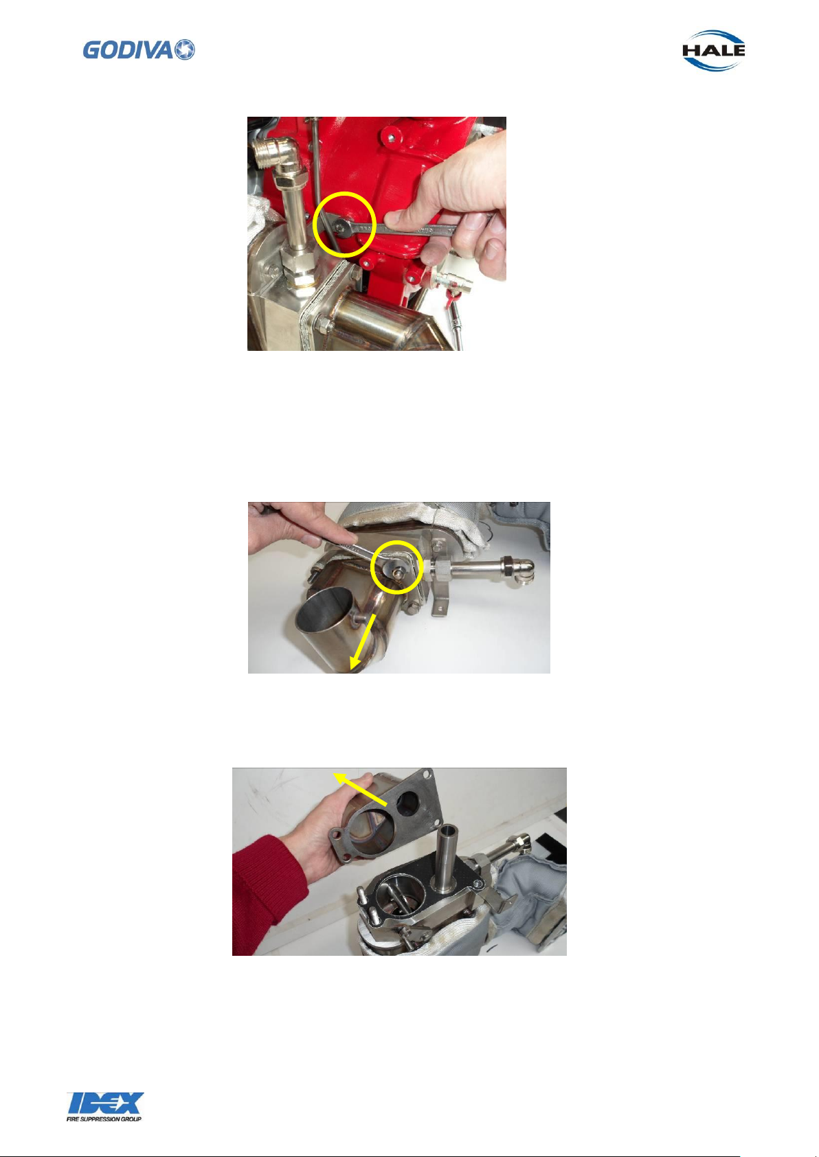
First, follow the procedure in sections 1.3 – 1.7 to disconnect and remove the priming
valve, including the removal of the side panel.
5.2 Remove the split pin and washer connecting the priming rod to the priming valve
5.3 Remove the 8 x M8 nuts holding the exhaust manifold to the engine.
It may be necessary to pull back the insulation blanket to allow access to the nuts.
5.4 Undo the bracket on the right, 1 x M6 bolt. The exhaust system can now be lifted
clear of the engine and pump.
Page 40
39
©Godiva Ltd. Our policy is one of continuous development. We therefore reserve the
right to amend specifications without notice or obligation.
5.5 Exhaust System
To inspect and repair the internal parts
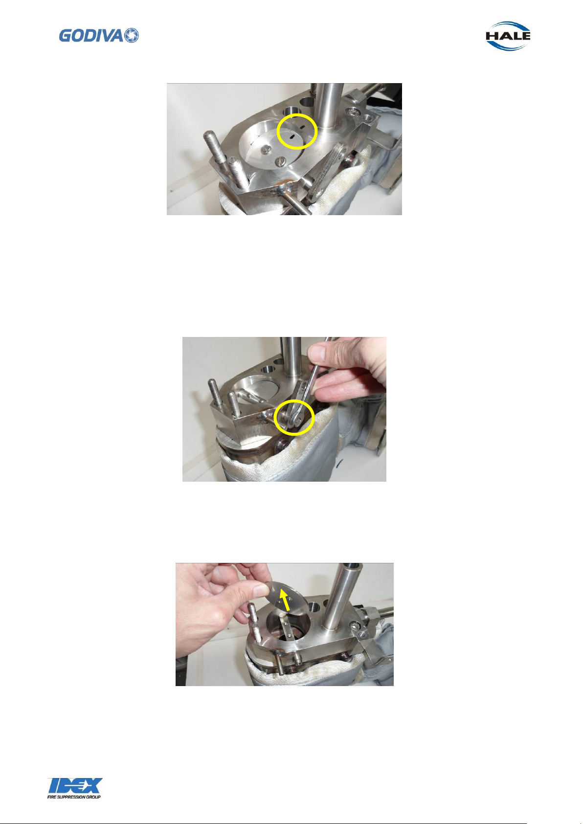
5.6 Undo and remove 4 x M8 Thick nuts and 4 x M8 thin nuts retaining the exhaust exit
to the exhaust primer housing
5.7 Removing the exhaust exit reveals the exhaust primer housing.
Note the gasket between the two parts, this should be replaced.
5.8 Before dismantling the exhaust primer housing, mark the position of the butterfly
valve in relation to the housing.
Page 41
40
©Godiva Ltd. Our policy is one of continuous development. We therefore reserve the
right to amend specifications without notice or obligation.
In the closed position the butterfly valve must make a complete seal in the housing. In
this position exhaust gases are diverted through the adjacent venture channel to create
the pump priming action.
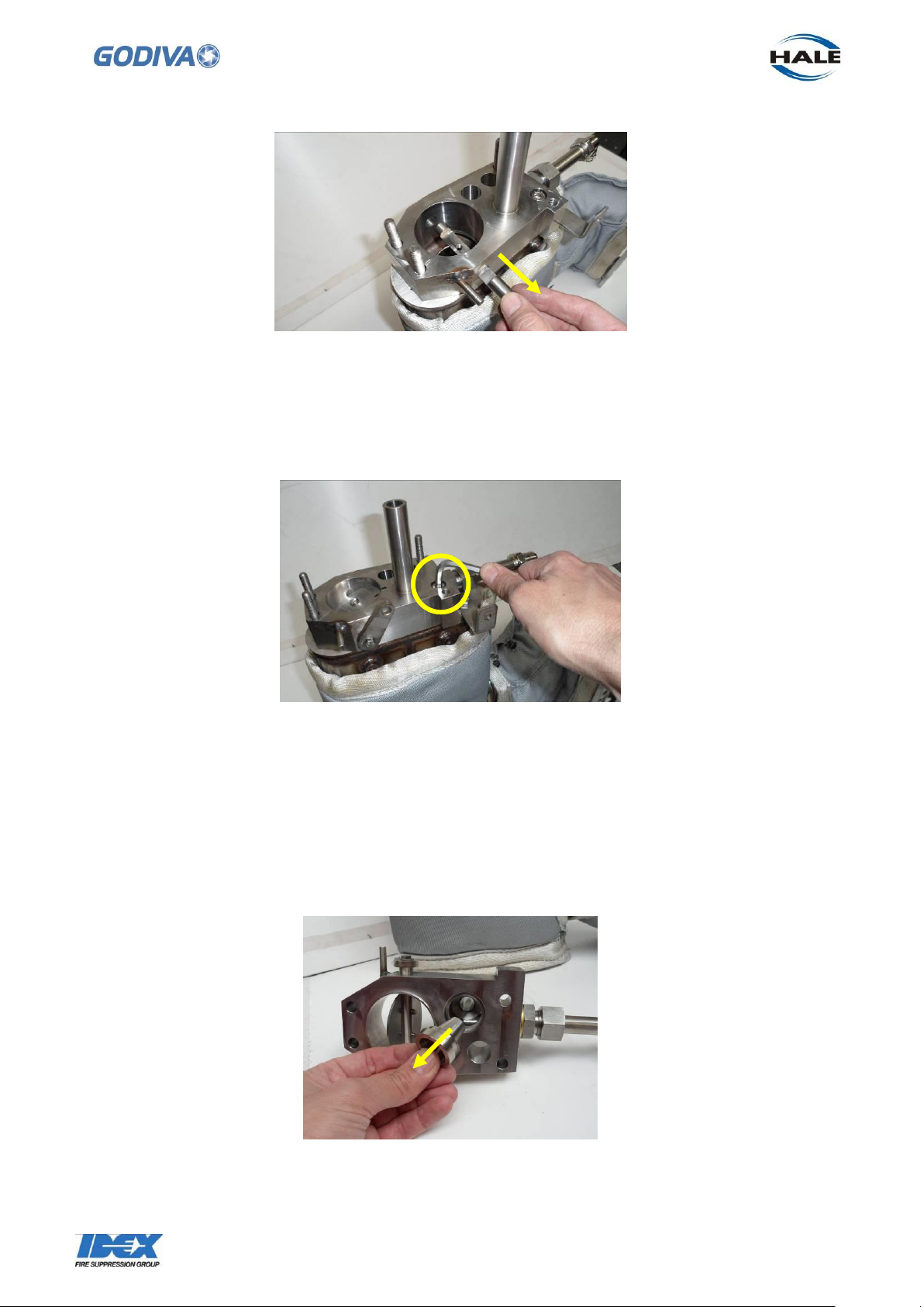
5.9 The butterfly valve can removed from the exhaust primer housing, while the
housing is attached to the silencer, first undo the M5 bolt and washer holding the lever
to the side of the housing.
5.10 Undo the two screws retaining the valve flap to the spindle and lift flap out of
housing.
The spindle can now be pulled away from the housing.
Page 42
41
©Godiva Ltd. Our policy is one of continuous development. We therefore reserve the
right to amend specifications without notice or obligation.
Inspect the valve flap to ensure the angled edges are still well defined, this will provide
a more effective seal in the primer housing.
5.11 The exhaust primer housing can now be detached from the silencer by undoing
the single M8 socket head screw in the corner.
5.12 Removing the exhaust primer housing allows access to the venturi nozzle.
The nozzle is located in the silencer side of the primer housing.
The nozzle is a push fit in the housing and should drop out when the housing is tapped
on a hard surface.
Check the nozzle for damage and replace if necessary.
Page 43
42
©Godiva Ltd. Our policy is one of continuous development. We therefore reserve the
right to amend specifications without notice or obligation.
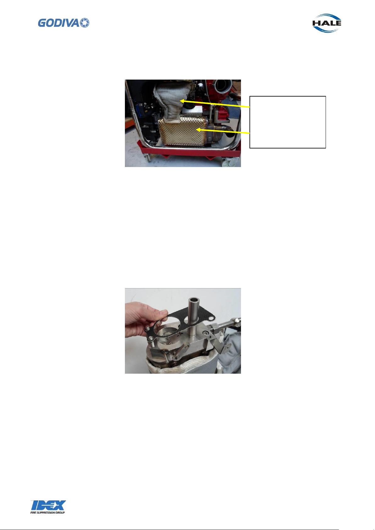
Insulation jacket –
can be removed
Insulation jacket permanent
5.13 The exhaust manifold and the silencer are welded together as one unit. The upper
part, the exhaust manifold, is covered by a heat insulating jacket.
The jacket is retained on the manifold by a series of wires, fastened to hooks, pulling
the jacket together. If necessary this jacket can be removed and replaced. The heat
insulation on the exhaust is permanent.
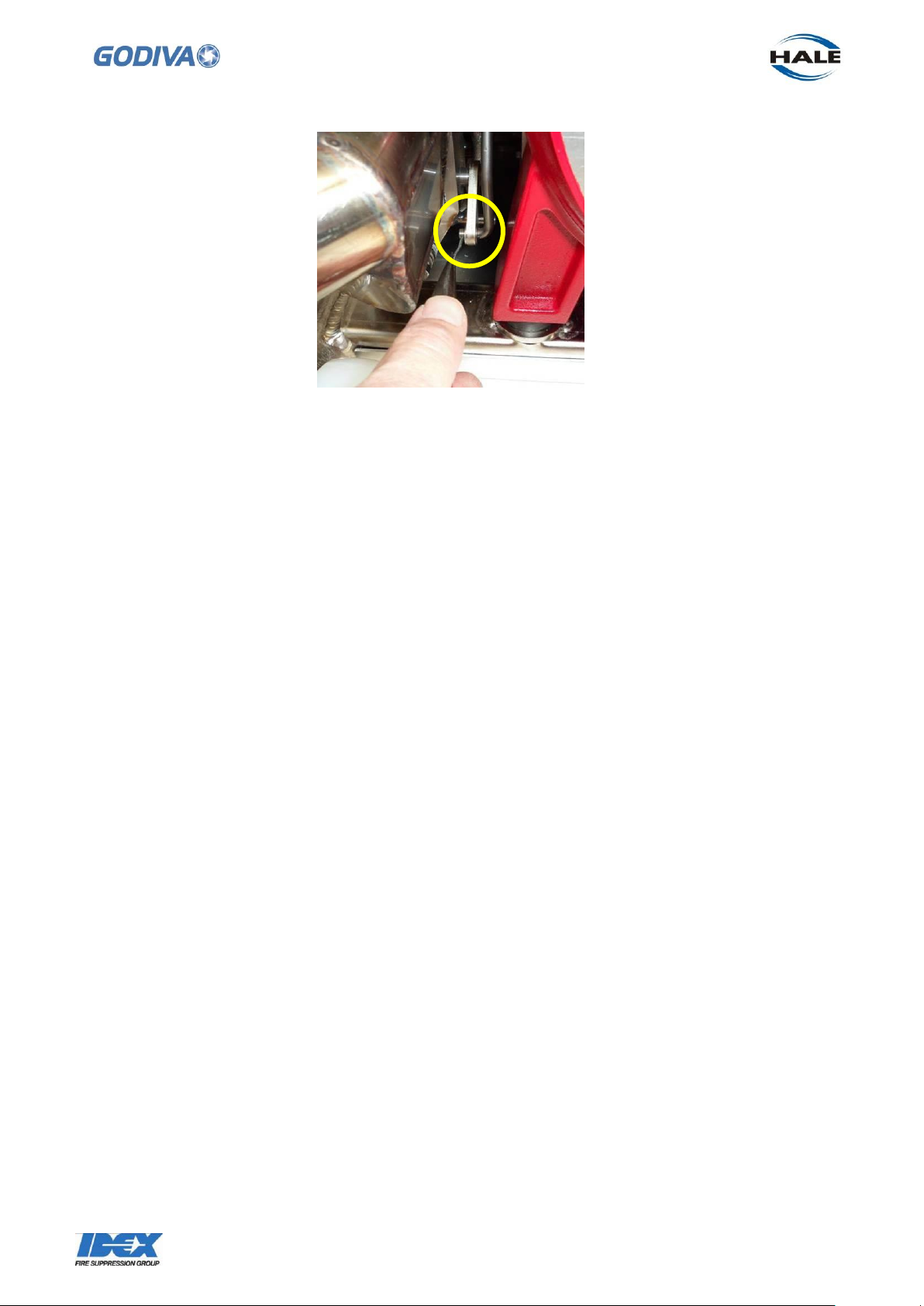
5.14 When all the internal parts have been checked the exhaust primer system can be
reassembled – a reversal of the dismantling process.
Ensure the gasket is replaced between the primer housing and the exhaust exit.
When securing the exhaust exit to the exhaust priming housing note the correct order
for the two types of nuts retaining the exhaust exit to the exhaust priming valve and
manifold – washer first, then the thin nut, then the thick nut last.
5.15 Do not forget to reconnect the priming rod to the lever on the side of the exhaust
priming valve housing.
Page 44
43
©Godiva Ltd. Our policy is one of continuous development. We therefore reserve the
right to amend specifications without notice or obligation.
Page 45
44
©Godiva Ltd. Our policy is one of continuous development. We therefore reserve the
right to amend specifications without notice or obligation.
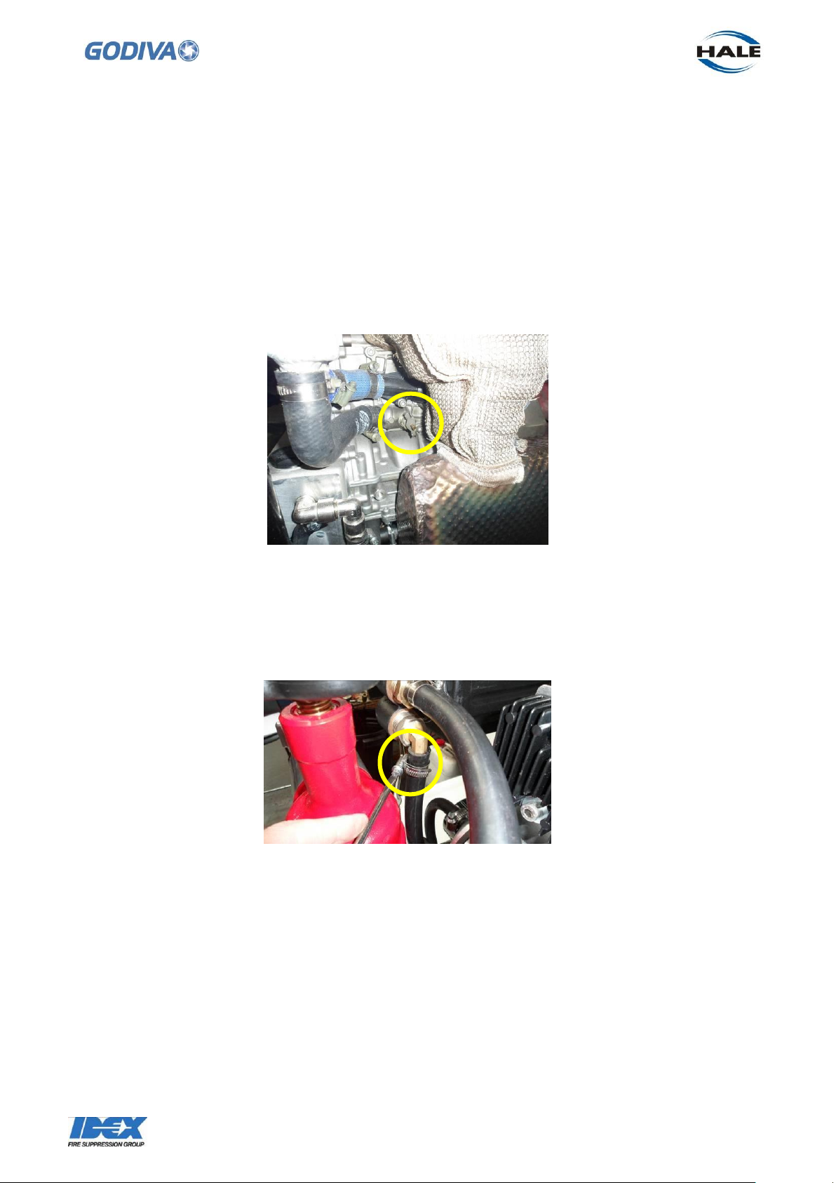
Detach the water return to suction hose at the suction tube.
6. Heat Exchanger
If the heat exchanger needs replacing follow these instructions.
Points to attend to –
Hoses, check condition for wear or leaks.
Check jubilee clips are sealing
If necessary drain the coolant from the system. A drain tap is provided on the side of
the engine. Attach a suitable hose to the tap before opening. Be careful not to spill or
splash the coolant on any components as it is a flammable liquid.
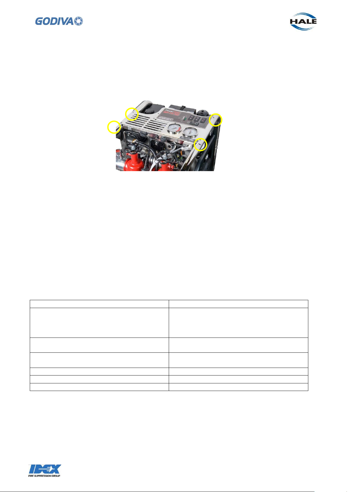
6.1 First remove the instrument panel on the top of the pump to gain better access to
the heat exchanger, see section 14 for more information.
6.2 Detach the four hoses connected to the heat exchanger Detach water supply hose to heat exchanger – detach at heat exchanger
Page 46
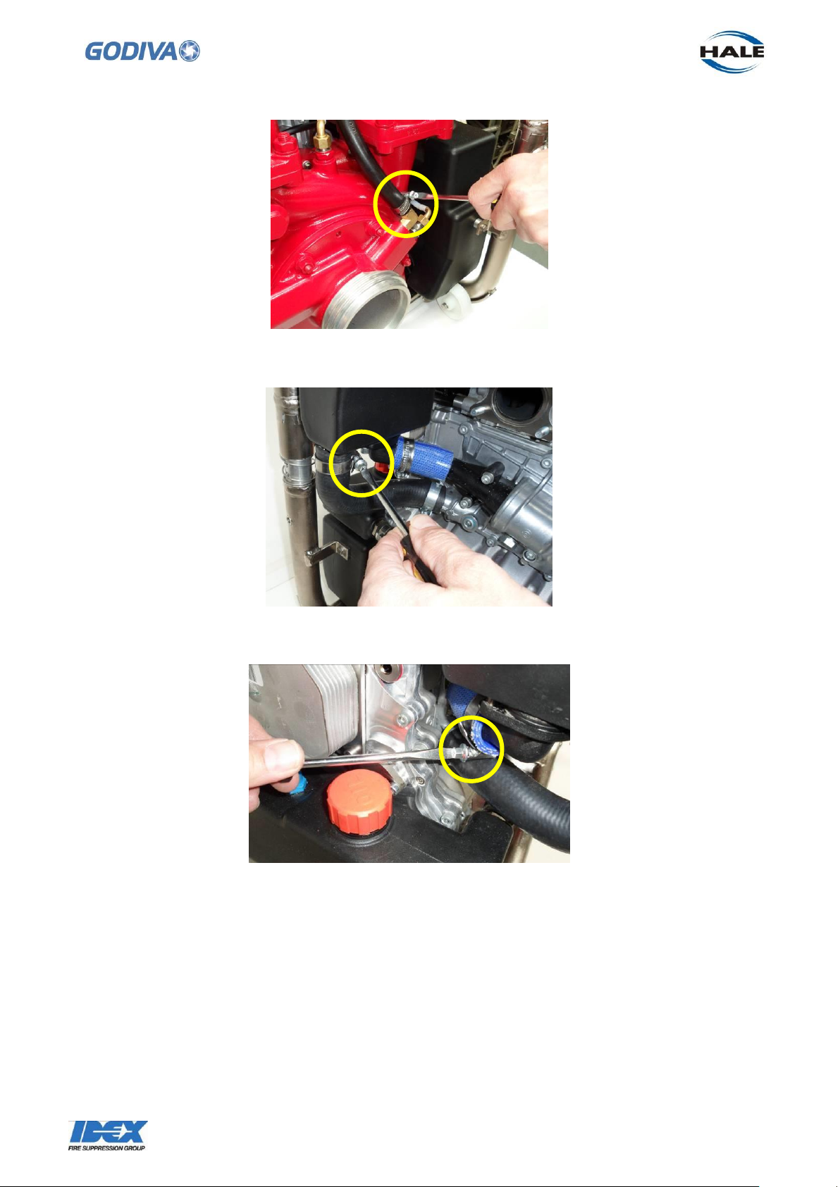
45
©Godiva Ltd. Our policy is one of continuous development. We therefore reserve the
right to amend specifications without notice or obligation.
Engine coolant into heat exchanger at the heat exchanger
Engine coolant return to engine at the heat exchanger
6.3 To release the heat exchange unit undo the 2 x M6 socket head screws on the top
bracket.
Page 47
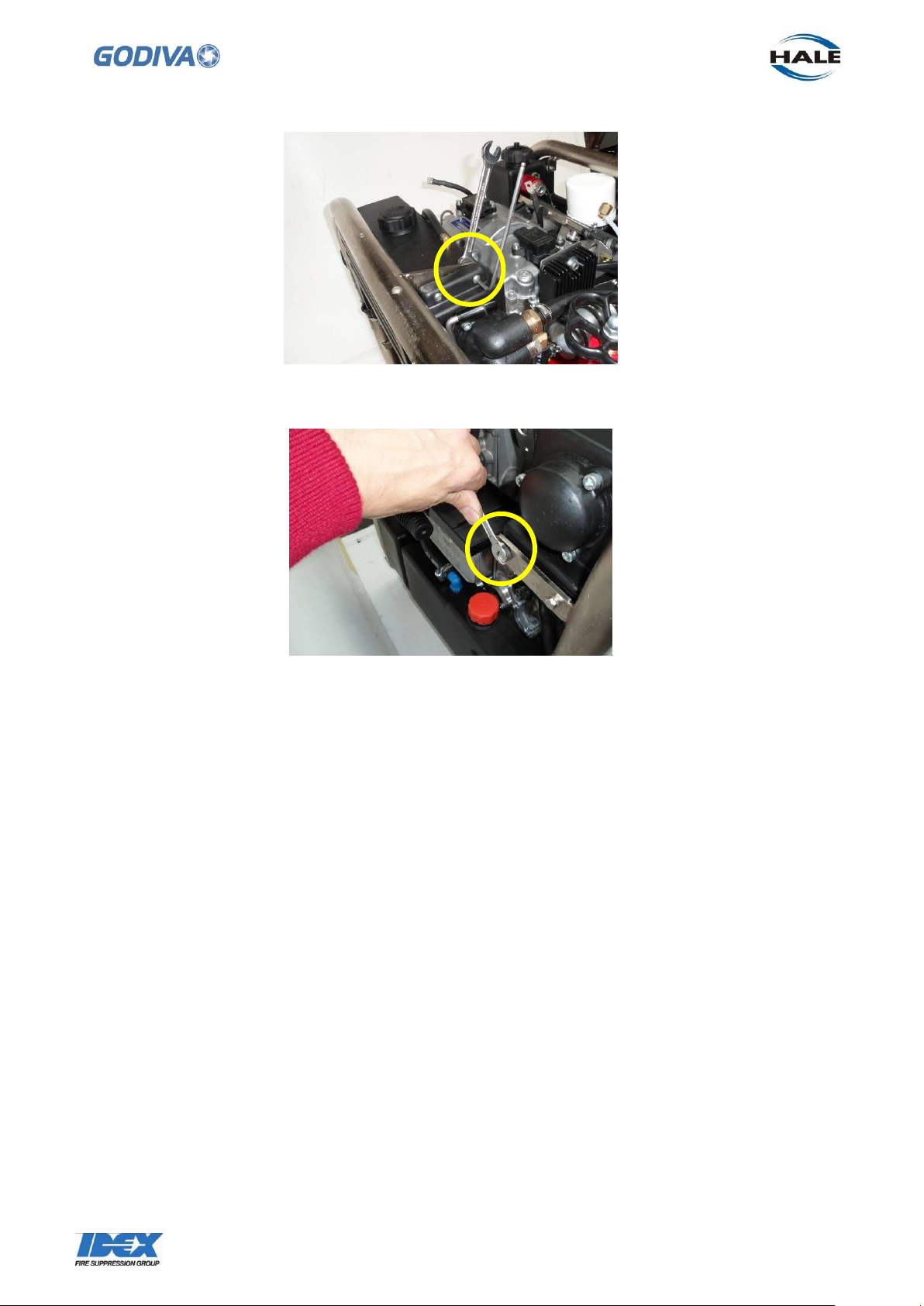
46
©Godiva Ltd. Our policy is one of continuous development. We therefore reserve the
right to amend specifications without notice or obligation.
6.5 With all hoses disconnected and fastenings undone it is possible to lift the heat
exchanger away from the frame – sideways and then up.
6.6 To replace, or fit a new heat exchanger, reverse the removal operation. Note that
the 2 x M6 screws on the rear bracket require a small amount of Loctite 243 on the
threads to secure.
6.4 Undo the 2 x M6 screws at the rear bracket.
7. Oil Tank
The oil tank is located at the rear of the pump. Please note the tank shown in this
sequence is a plastic material, later oil tanks are made of aluminium.
If the tank needs changing follow these instructions –
7.1 To drain the oil from the tank and engine, a ¼ inch BSP drain plug is located in the
bottom of the tank towards the right side. The plug is accessible through the skid plate
on the bottom of the frame. 13mm socket is required.
Page 48
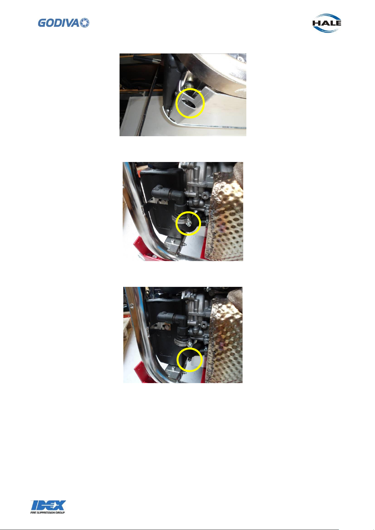
47
©Godiva Ltd. Our policy is one of continuous development. We therefore reserve the
right to amend specifications without notice or obligation.
7.2 Undo the two hoses feeding oil to and from the tank.
7.3 Undo the 1 x M6 bolt on the side of the frame.
Page 49

48
©Godiva Ltd. Our policy is one of continuous development. We therefore reserve the
right to amend specifications without notice or obligation.
7.4 Undo the 2 x M10 bolts holding the tank to the frame, on the underside of the
pump. The skid plate needs to be removed to gain access to these two bolts, undo the
4 x M6 socket head screws at each corner of the plate to remove it from the bottom of
the pump frame.
7.5 To release the oil tank form the pump the breather hose connected to the top of the
tank needs to be removed from the elbow. It may be necessary to cut, and sacrifice the
hose at the oil tank in order to free the tank
7.6 To replace the tank, or fit a new tank, the assembly process is a reversal of the
removal process. Fit a new breather hose if necessary
Note: when replacing the skid plate apply a small amount of Loctite 243 to the threads
of the 4 x M6 socket head screws retaining the plate to the pump frame.
Page 50
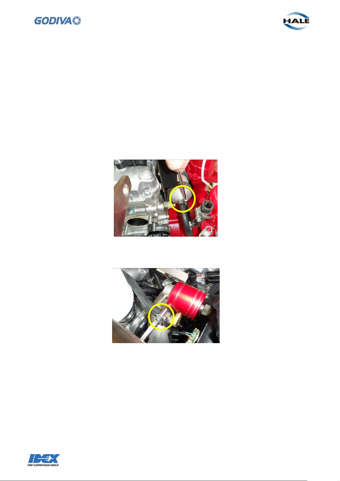
49
©Godiva Ltd. Our policy is one of continuous development. We therefore reserve the
right to amend specifications without notice or obligation.
8. Fuel Tank
To remove and replace the fuel tank follow these instructions.
If necessary, drain the fuel tank. This is achieved by pumping the fuel from the tank
through the filler cap.
The only way to remove the fuel tank is to remove the complete pump and engine
assembly first to allow the tank to be lifted clear of the frame.
This sequence of removing the major assemblies should be followed – first remove the
oil tank (section 7), instrument panel (section 14), heat exchanger (section 6).
Separate the engine from the panel wiring harness. Disconnect the tank level sensor
harness from the panel. Then follow this sequence -
8.1 Disconnect the fuel supply hose to the fuel filter at the front of the pump.
8.2 Disconnect the fuel hose to the pressure regulator (located on the side of tank
towards the rear) – the hose may need to be cut to release it)
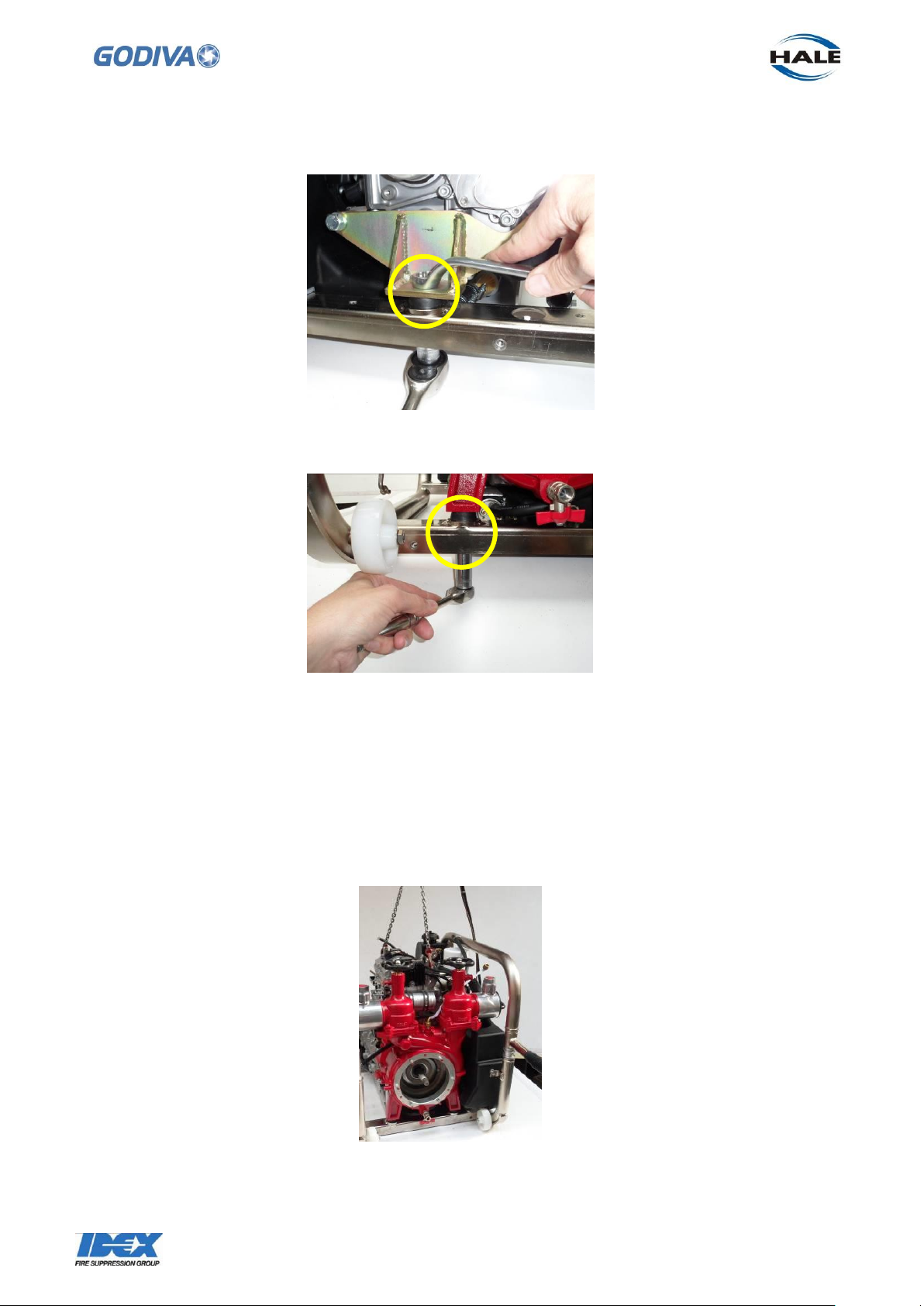
8.3 Undo the 3 pump and engine mounting points. The single rear mounting point is a
M10 bolt. The front two mounting points are studs inserted in the pump secured to the
frame by 2 x M10 nuts.
Page 51
50
©Godiva Ltd. Our policy is one of continuous development. We therefore reserve the
right to amend specifications without notice or obligation.
Undoing the front pump/engine mount.
Undoing rear pump/engine mount.
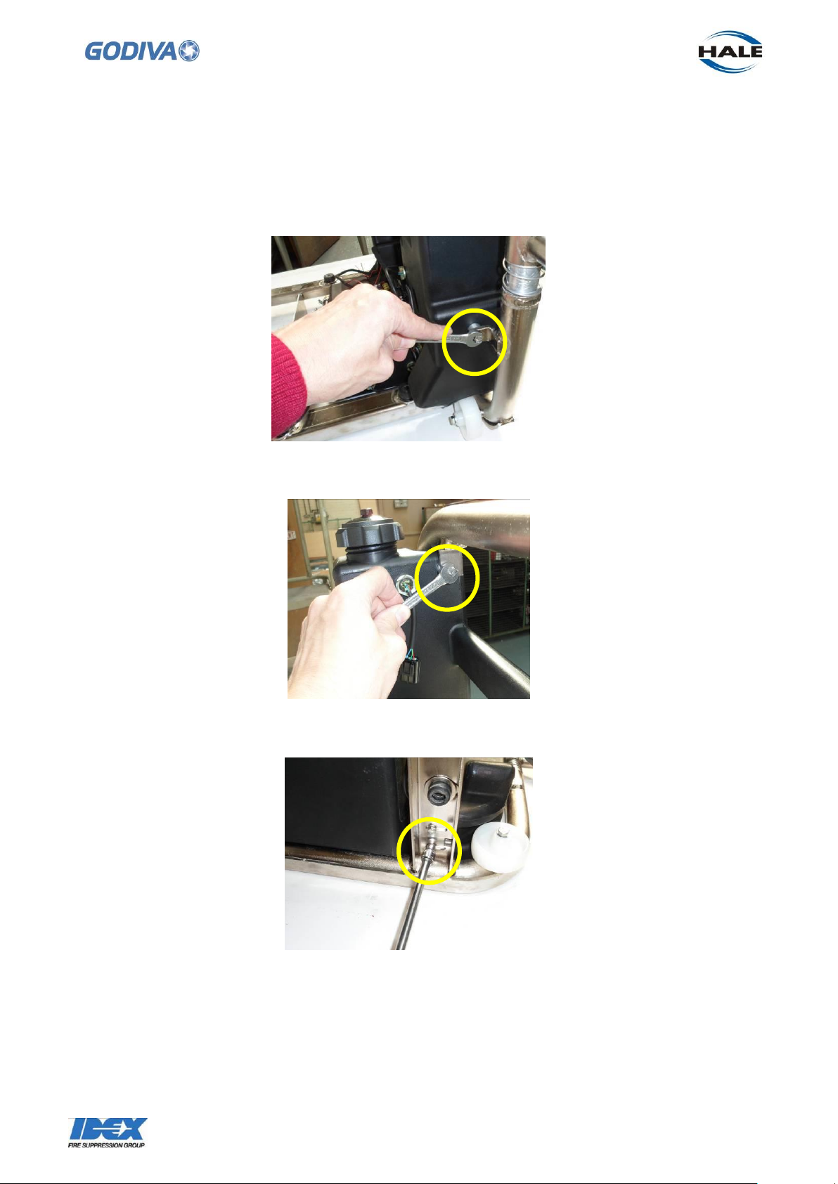
8.4 To allow the pump/engine assembly to be lifted clear of the frame, the two sides of
the frame must be separated.
The exhaust side of the frame (hot side) is secured to the fuel tank side (cold side) by
2 x M6 60mm bolts and 2 x M6 20mm bolts. Undoing these bolts allows the hot side of
the frame to be removed.
8.5 Using a powered hoist lift the pump/engine assembly clear of the frame.
Page 52
51
©Godiva Ltd. Our policy is one of continuous development. We therefore reserve the
right to amend specifications without notice or obligation.
8.6 When lifting the pump/engine assembly away from the frame it is advisable to
remove the air filter assembly from the throttle body on the air intake.
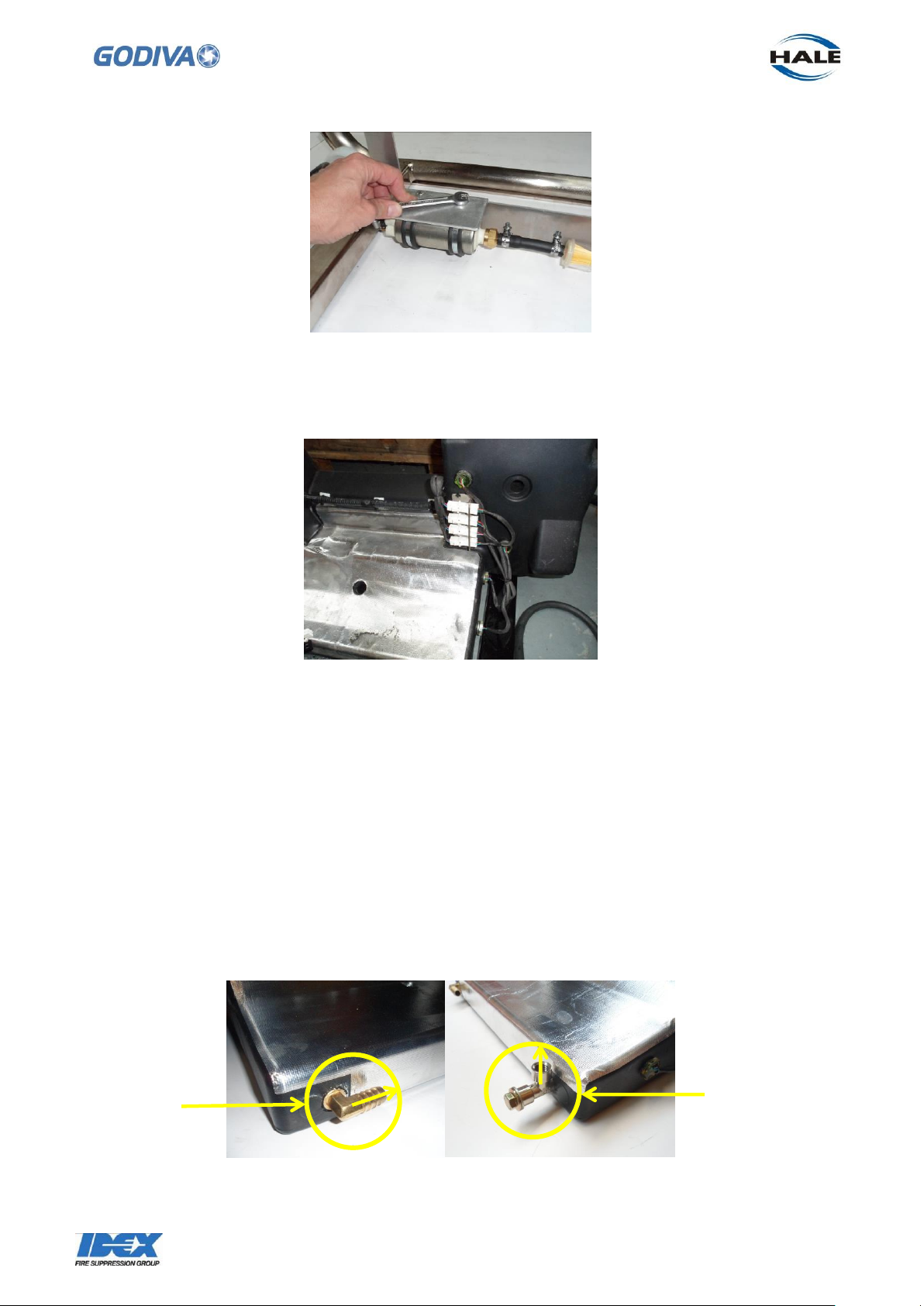
8.7 With the pump/engine assembly removed the fuel tank is exposed.
Continue to remove the fuel tank by undoing the 6 x M6 bolts holding it to the frame.
Four of the bolts are underneath the fuel tank
8.8 The fuel pump can be removed by undoing the 3 x M6 bolts and nuts holding the
pump to the frame.
Page 53
52
©Godiva Ltd. Our policy is one of continuous development. We therefore reserve the
right to amend specifications without notice or obligation.
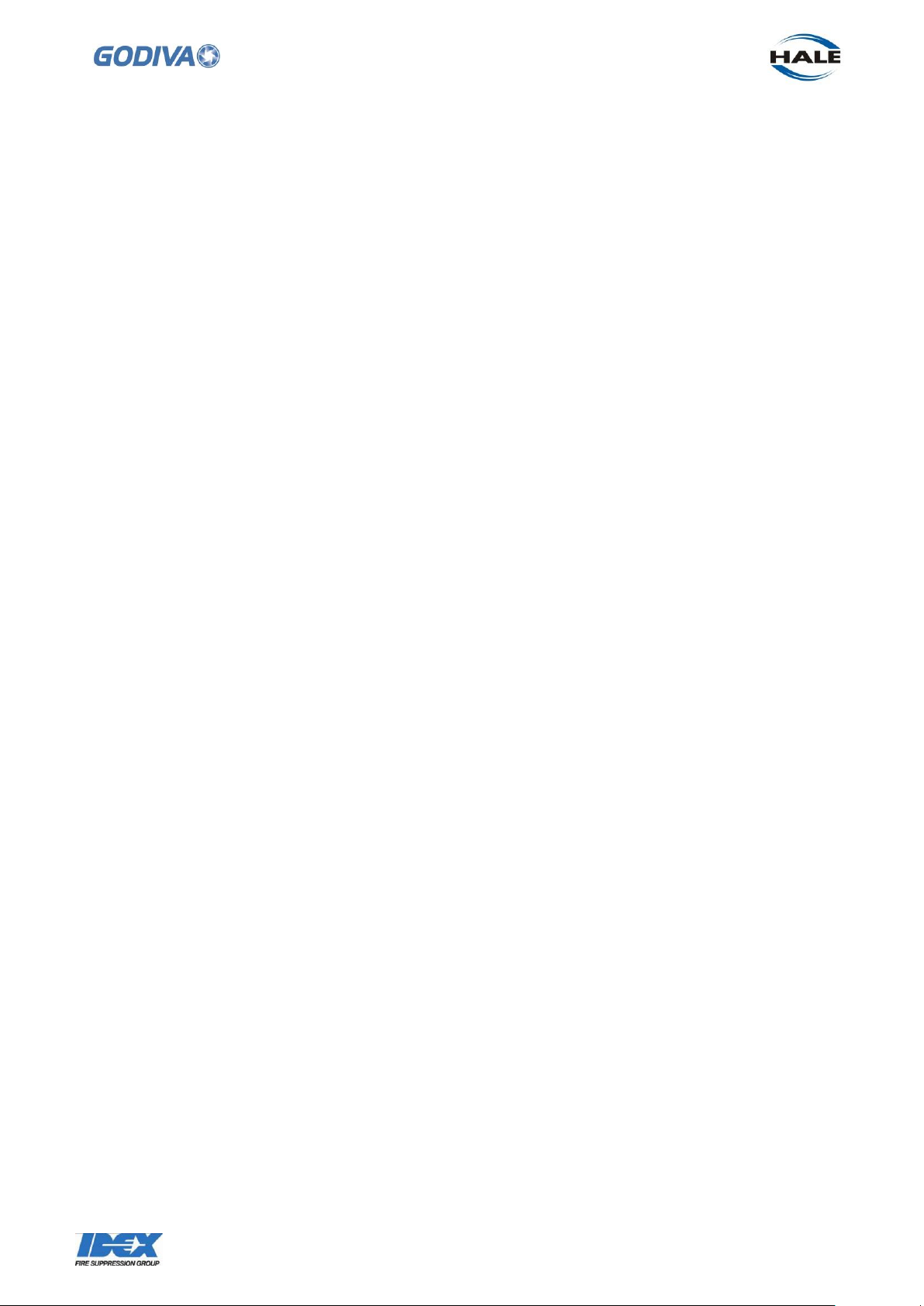
Equal tee
(65572)
Fuel filter
(68158)
8.9 The fuel tank is fitted with a wiring harness linking to 5 fuel level sensors. If there is
any damage to the harness or connections these must be replaced as a complete
harness.
8.10 To replace the fuel tank or fit a new tank, it is a reversal of the removal process.
It is advisable to tape the wiring harness in place on the tank to ensure it does not
obstruct or snag when replacing the tank.
Note: the M6 bolts at each end of the fuel tank are longer than the ones under the tank.
Apply a small amount of Loctite 243 to the threads of all the 6 x M6 bolts before
securing the tank back into the frame.
8.11 There are two fittings inserted into the tank body – fuel filter (68158) and equal tee
(65572). If these need to be replaced, then apply Loctite 410 on the thread of both
fittings and Loctite 770 activator to the thread in the tank body, just before inserting the
fittings. The combination of the two Loctite applications will form a secure seal.
Note the orientation of the fixings in the tank.
Page 54
53
©Godiva Ltd. Our policy is one of continuous development. We therefore reserve the
right to amend specifications without notice or obligation.
Page 55
54
©Godiva Ltd. Our policy is one of continuous development. We therefore reserve the
right to amend specifications without notice or obligation.
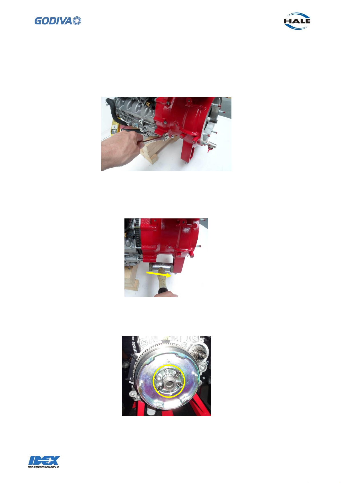
9. To remove pump body from the engine
With the pump and engine removed from the frame, support this assembly on blocks to
prevent falling over.
9.1 Undo the 9 x M6 nuts and 2 x M10 nuts on studs retaining the pump to the engine.
9.2 The pump assembly can now be moved forward from the engine, gently tap the
pump body, with a plastic hammer to dislodge it from the engine.
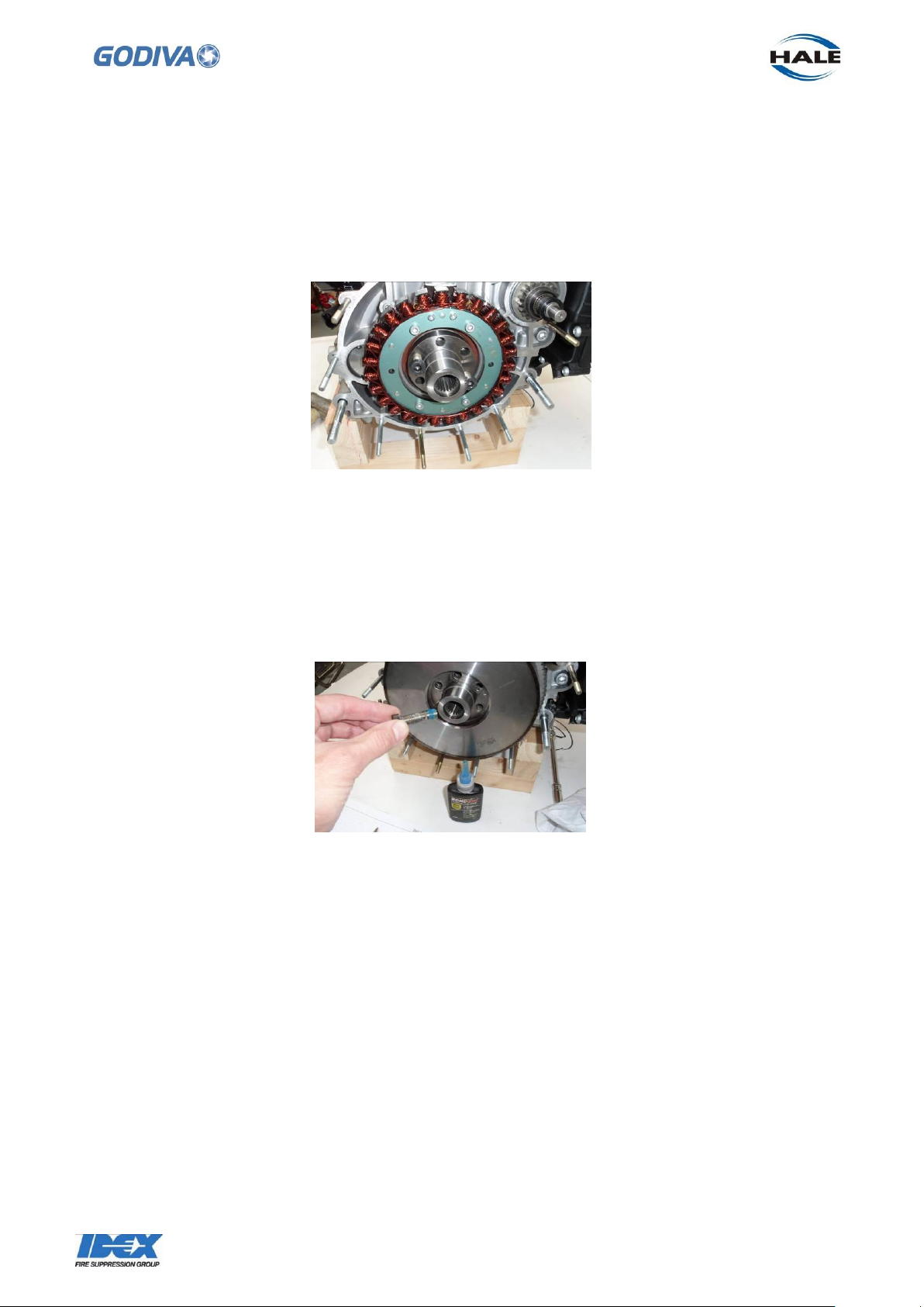
9.2 This reveals the stub shaft protruding through the centre of the rotor. To remove
the stub shaft and rotor, undo the 6 off socket head screws retaining the stub shaft to
the engine. The stub shaft also retains the rotor and recoil starter pulley.
9.3 The stub shaft can then be removed from the engine by gently knocking with a
hammer.
Page 56
55
©Godiva Ltd. Our policy is one of continuous development. We therefore reserve the
right to amend specifications without notice or obligation.
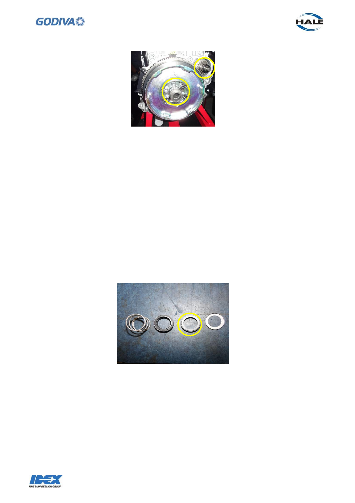
9.4 To replace the stub shaft and rotor. First place the stub shaft against the
corresponding holes in the end of the crankshaft.
Clean the threads of the 6 off socket head screws to remove old sealant.
9.5 Use 2 of the screws to guide the stub shaft to the correct location on the crankshaft
end. When the stub shaft is in place remove the 2 screws.
9.6 Place the rotor on to the crankshaft over the stub shaft and tap into place being
careful not to disturb the location of the stub shaft. The teeth on the outer edge of the
rotor will engage with teeth on the starter motor.
9.7 Apply a sealant (Loctite 243 or equivalent) to the 6 off socket head screws and
insert screws into the stub shaft. Tighten each screw to a torque setting of 60Nm.
10. Replacing Pump on to Engine
When replacing the pump assembly back to the engine, note these points –
The pump and engine are best joined together outside of the frame.
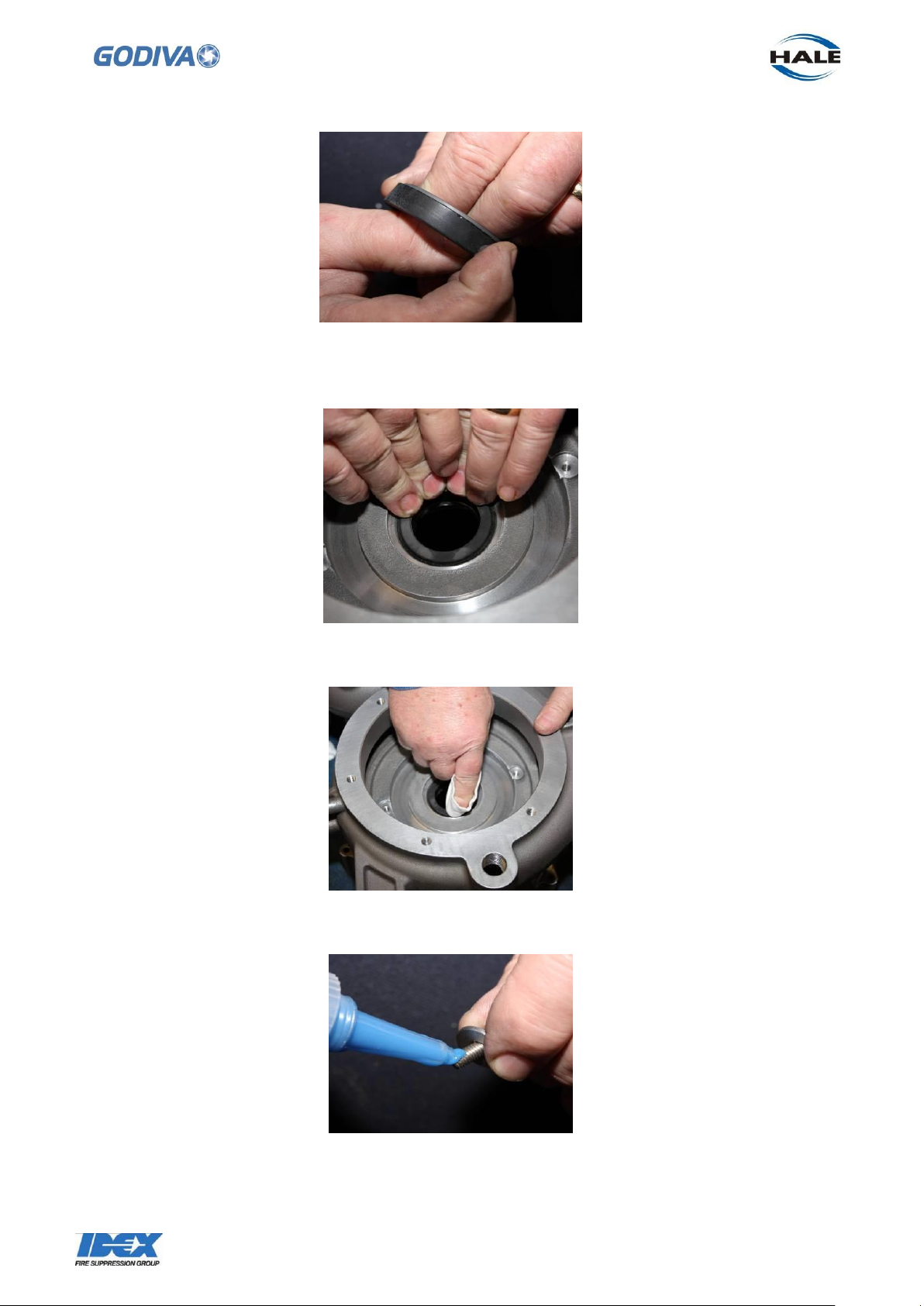
10.1 The pump body houses a bush that provides a location for the starter motor shaft.
This is on the right side of the pump as viewed from the front.
At the same time the pump shaft which is splined, can be located into the internal
splines of the stubb shaft. Grease all the splines with CV grease.
Page 57
56
©Godiva Ltd. Our policy is one of continuous development. We therefore reserve the
right to amend specifications without notice or obligation.
10.2 Before assembly grease the shaft splines with CV grease When the pump shaft is
located into the stub shaft and the starter motor, ease the pump back against the
engine.. The pump body locates on to 11 x studs protruding from the engine.
10.3 Tap the pump body gently against the engine. Tap evenly around the outer edge
of the pump.
10.4 Replace the 9 x M6 nuts, and 2 x M10 nuts around the outside edge of the pump.
Tighten the 2 x M10 nuts first, then the 9 x M6 nuts evenly around the pump.
11. Pump Assembly
If it is necessary to rebuild the pump assembly from components follow this procedure.
11.1 Take the mechanical seal (296-5250-08-0) components from the box supplied.
11.2 Apply a soft soap solution to the outside of this seal part. Do not allow grease to
touch the sealing surfaces seal as this will ruin the sealing capability.
Page 58
57
©Godiva Ltd. Our policy is one of continuous development. We therefore reserve the
right to amend specifications without notice or obligation.
11.6 Tighten the retaining screws to 2 Nm.
11.3 Press the seal into the pump volute, evenly. Ensure it is pressed to the bottom of
the recess and is flush with the surface of the pump volute.
11.4 Clean the surface of the seal with solvent cleaner
11.5 Fit the rear wear ring, Apply Loctite 243 to the retaining screws
Page 59
58
©Godiva Ltd. Our policy is one of continuous development. We therefore reserve the
right to amend specifications without notice or obligation.
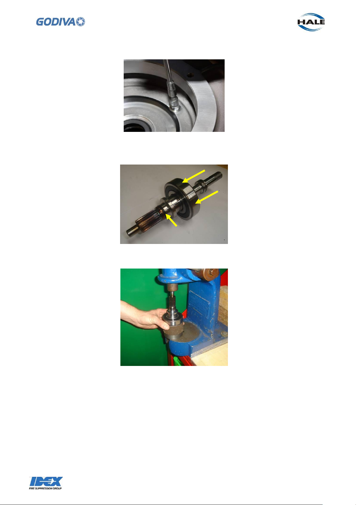
11.7 Press bearing (68170) onto the shaft. Also place O ring (57044) into the groove
next to the shaft splines.
11.8 Use a press to move the bearing down to the shoulder on the shaft
11.9 Fit the collar (68024) on to the shaft
Page 60
59
©Godiva Ltd. Our policy is one of continuous development. We therefore reserve the
right to amend specifications without notice or obligation.
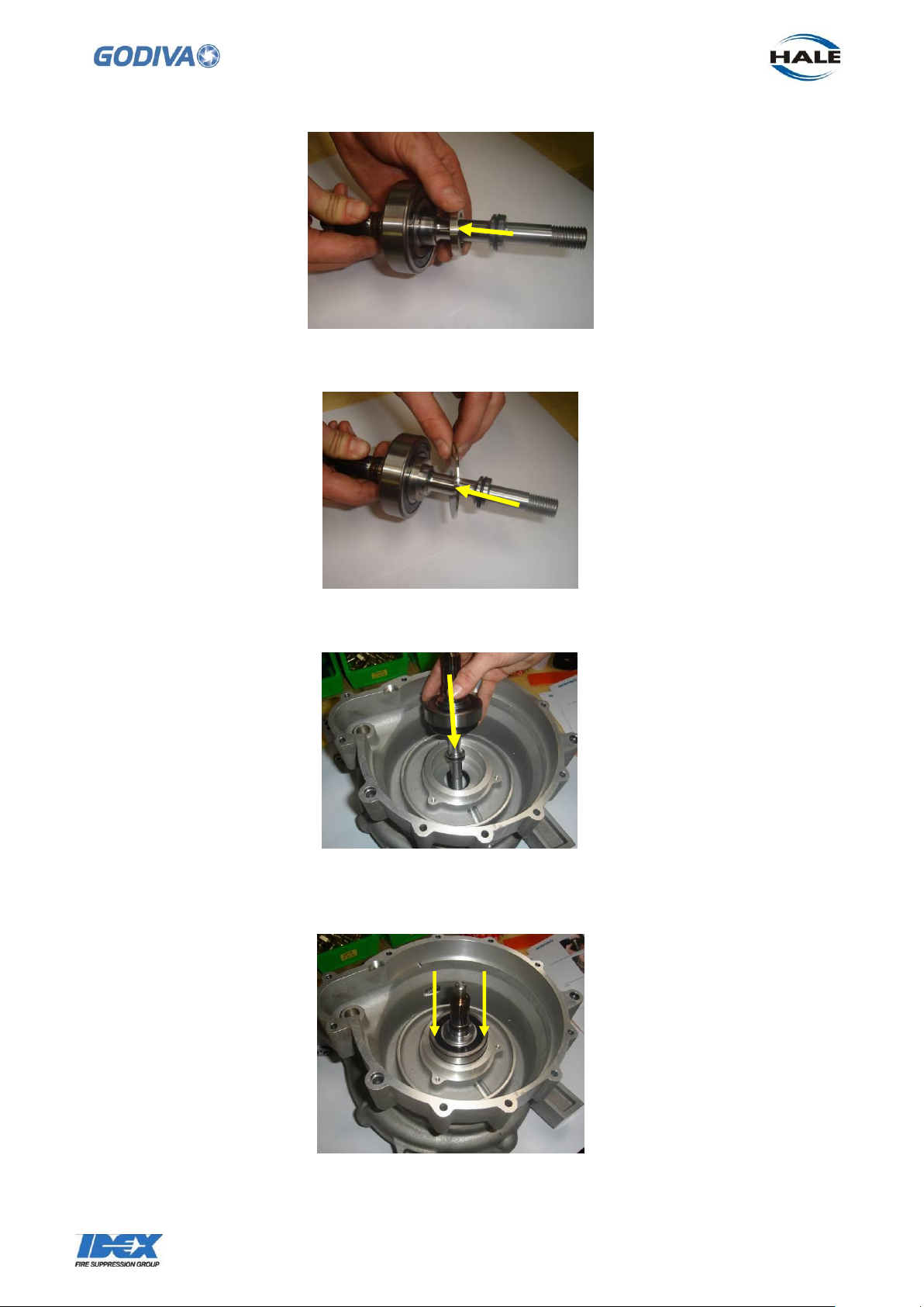
11.11 Fit the shaft, with the collar and flinger facing down, into the rear of the pump.
11.10 Fit the flinger (68033) on to the shaft.
11.12 Tap evenly around the edge of the bearing to force the assembly into the pump
volute.
Page 61

60
©Godiva Ltd. Our policy is one of continuous development. We therefore reserve the
right to amend specifications without notice or obligation.
11.13 Use a suitable ring tool to push the bearing and shaft further into the pump
11.14 Push the bearing into the pump body until it passes the internal circlip groove.
11.15 Insert the circlip (53527) using suitable circlip pliers to retain the bearing and
shaft
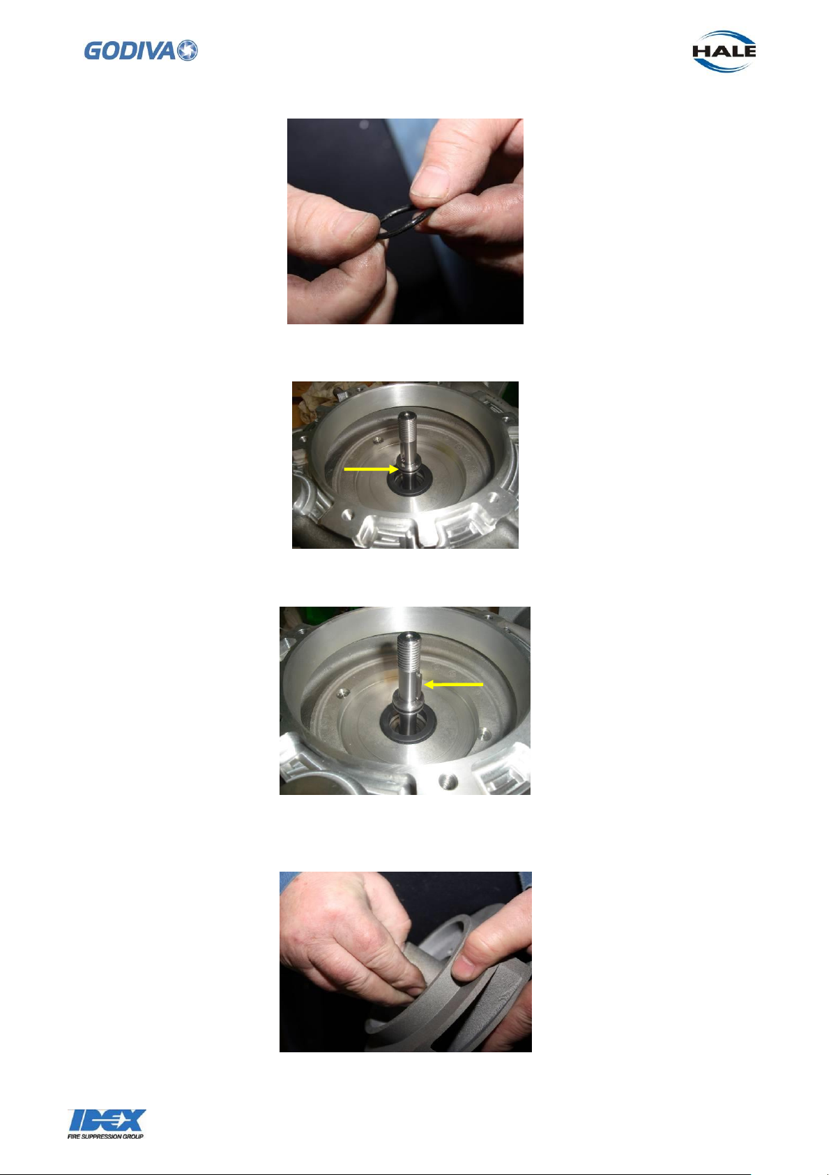
11.16 Turn the volute over. Smear grease all over the O ring (57129)
Page 62
61
©Godiva Ltd. Our policy is one of continuous development. We therefore reserve the
right to amend specifications without notice or obligation.
11.17 Fit the O ring to the impeller end of the shaft.
11.18 Place the key (MS179/36) into the slot on the shaft
11.19 Apply a soft soap solution, or Rubber Lube, to the impeller inside and outside on
the rear central section
Page 63
62
©Godiva Ltd. Our policy is one of continuous development. We therefore reserve the
right to amend specifications without notice or obligation.
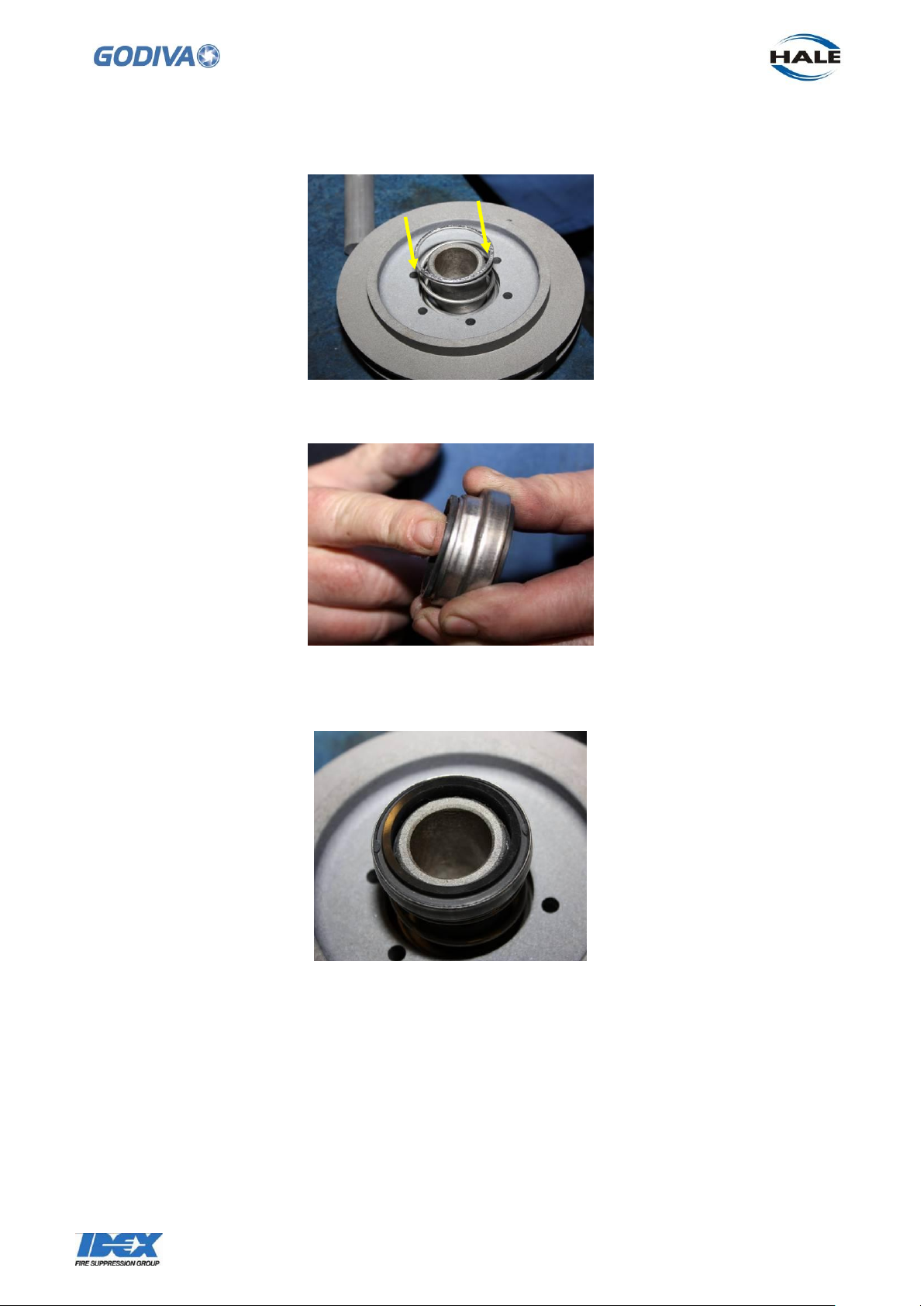
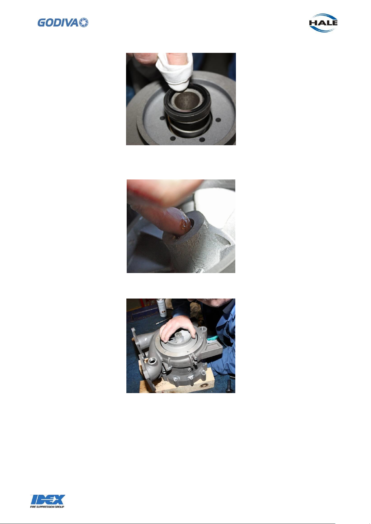
11.22 Push the seal onto the impeller and press down against the spring until it rests
just above the impeller central section.
11.20 Place the spring from the seal kit over the impeller rear central section.
11.21 Apply a soft soap solution to the internal part of the seal
11.23 Clean the carbon surface of the seal with solvent cleaner (Loctite 7063 or
similar)
Page 64
63
©Godiva Ltd. Our policy is one of continuous development. We therefore reserve the
right to amend specifications without notice or obligation.
11.25 Press the impeller down on to the shaft. Ensure the slot in the impeller lines up
with the key on the shaft.
11.24 The impeller can now be fitted to the shaft. Grease the end of the shaft and
inside impeller.
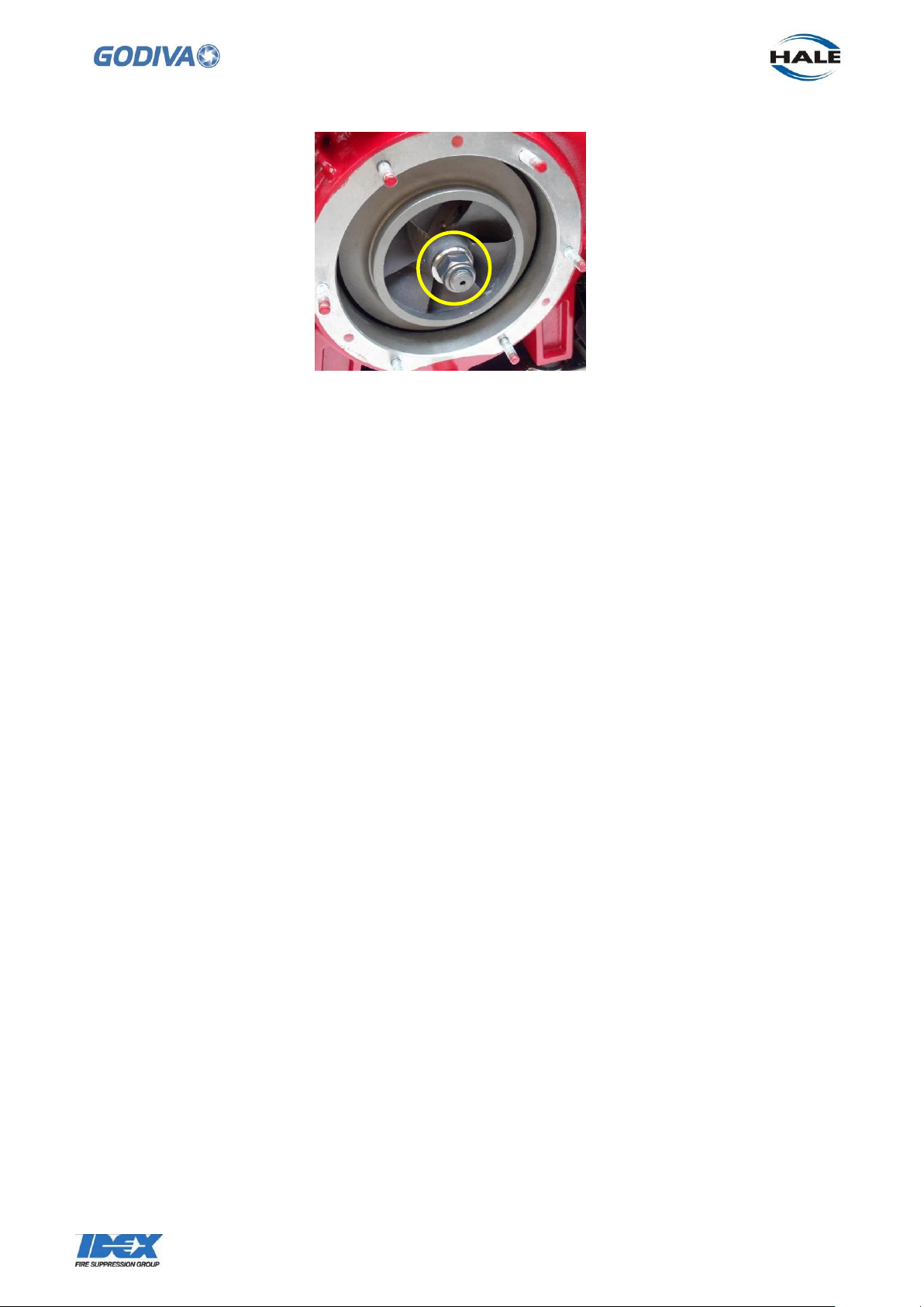
11.26 Fit the washer and a new nyloc nut to secure the impeller to the shaft. Tighten
the nut on the shaft to a torque of 45 Nm, this is sufficient to push the impeller back
into position.
Page 65
64
©Godiva Ltd. Our policy is one of continuous development. We therefore reserve the
right to amend specifications without notice or obligation.
Page 66
65
©Godiva Ltd. Our policy is one of continuous development. We therefore reserve the
right to amend specifications without notice or obligation.
12. Recoil Start
If the recoil starter needs replacing or the pull cord needs replacing follow this
procedure.
Access to the recoil starter is achieved when the pump end is separated from the
engine.
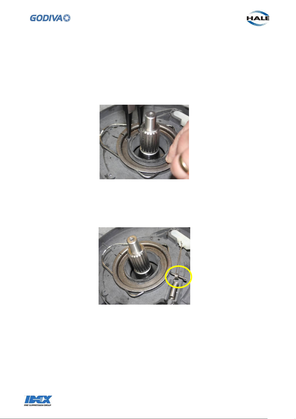
12.1 The recoil start mechanism is retained in the rear of the volute by a circlip.
Remove the circlip with circlip pliers to access the reel.
12.2 The plate and clip on top of the reel can now be released. Note the location of the
extended end of the clip on the right, this must rest in the ratchet guide hole when
reassembling.
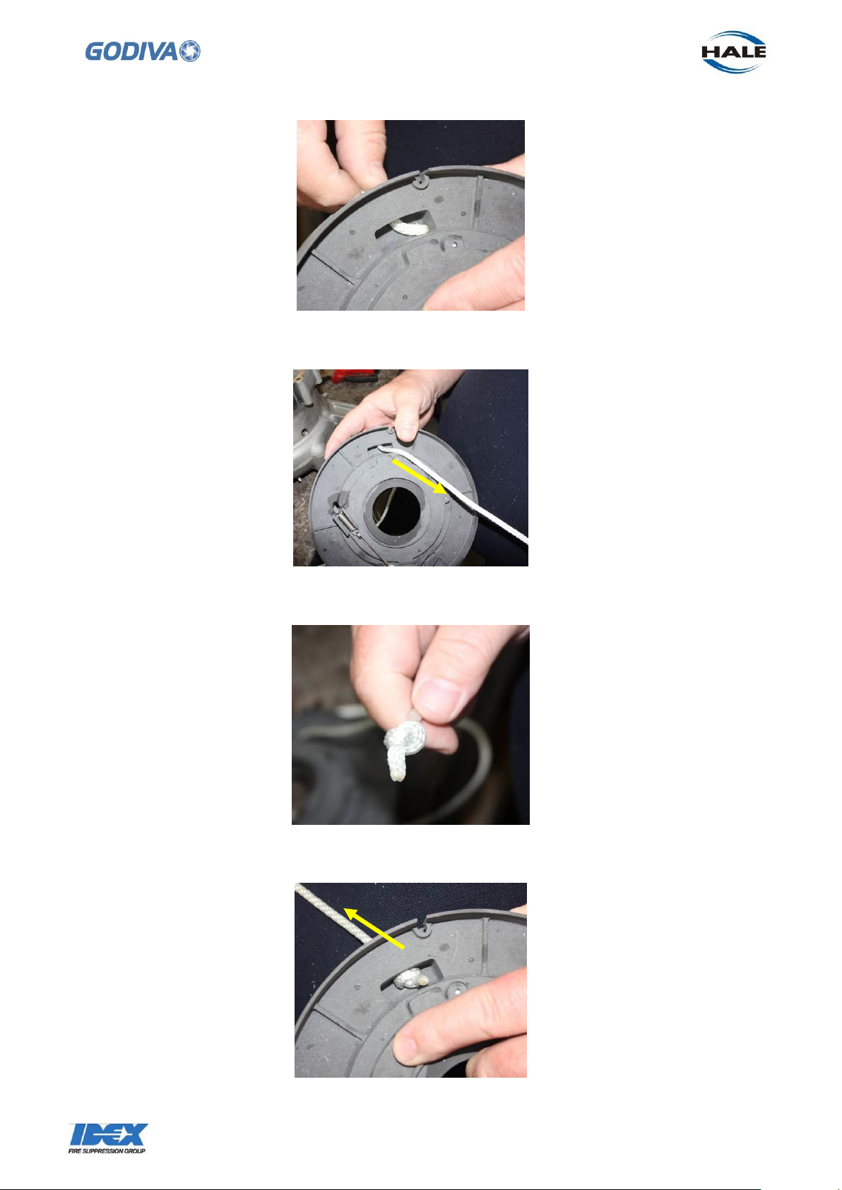
12.3 When the reel is free from the pump volute. A new rope can be threaded through
the hole in the reel.
Page 67
66
©Godiva Ltd. Our policy is one of continuous development. We therefore reserve the
right to amend specifications without notice or obligation.
12.4 Pull most of the rope through the reel.
12.5 Tie a knot in the rope end.
12.6 Pull the rope back through the reel until the knot is retained in the slot
Page 68
67
©Godiva Ltd. Our policy is one of continuous development. We therefore reserve the
right to amend specifications without notice or obligation.
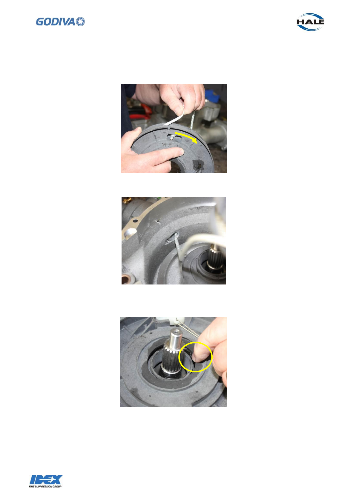
12.7 Wrap the rope firmly around the reel in a clockwise direction, for four turns.
12.8 Thread the other end of the rope through the hole the volute to the outside.
12.9 Place the complete reel back over the shaft and onto the block.
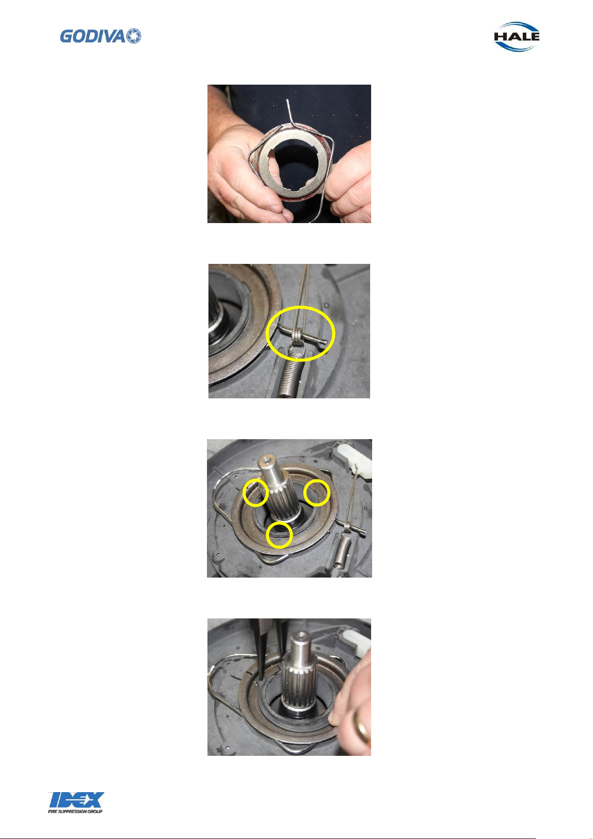
Make sure the spring is located in the block -
12.10 Fit Clip to the plate making sure the straight end of the Clip is on the right side
looking from the back
Page 69
68
©Godiva Ltd. Our policy is one of continuous development. We therefore reserve the
right to amend specifications without notice or obligation.
12.11 Place the Straight end of the Clip through the ratchet guide hole as shown below
12.12 Line the Plate grooves up with the Block grooves as shown below
12.13 Secure the plate to the block and the volute with the circlip
Page 70
69
©Godiva Ltd. Our policy is one of continuous development. We therefore reserve the
right to amend specifications without notice or obligation.
12.14 Pull the other end of the rope right through the handle, length should be
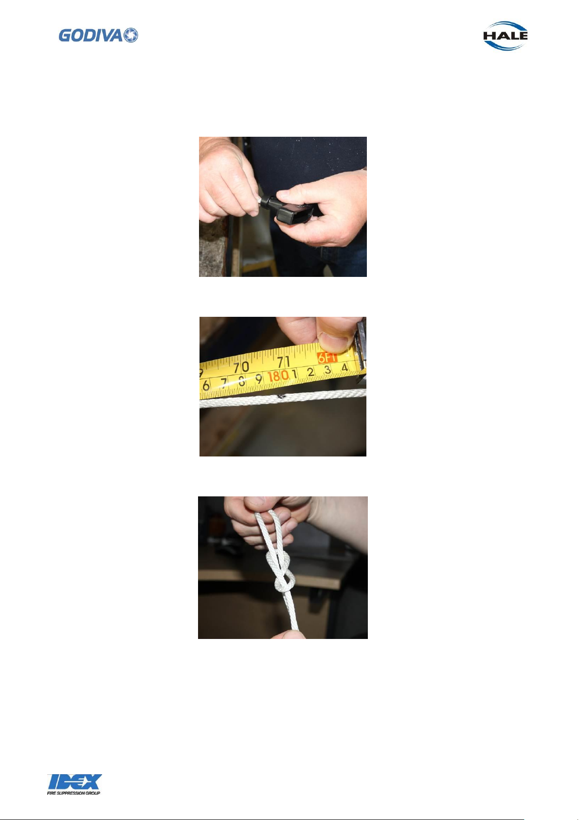
1800mm.
Make a mark where the 1800mm length should be.
12.15 Tie a secure slip knot in the end of the rope that has gone through the handle
12.16 Tighten the knot as close as possible top the black mark and cut off the excess
rope.
Page 71
70
©Godiva Ltd. Our policy is one of continuous development. We therefore reserve the
right to amend specifications without notice or obligation.
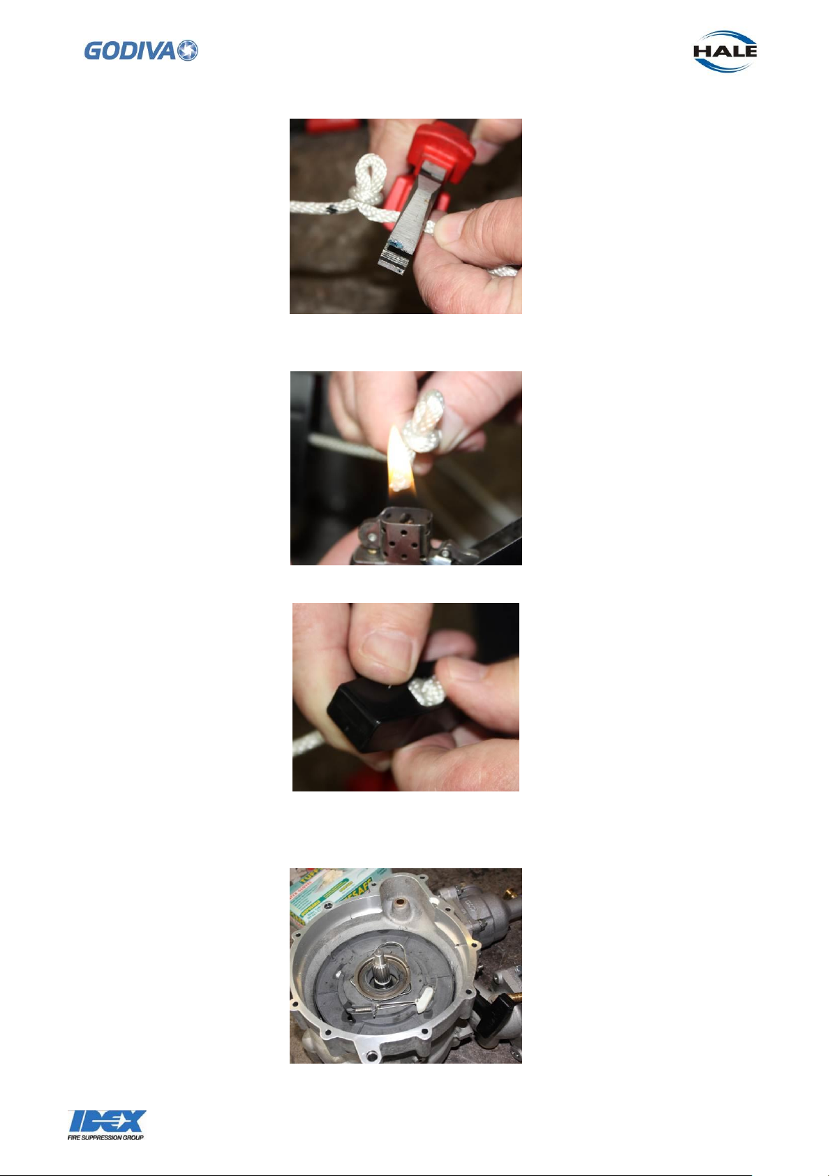
12.17 Burn the end of the rope to prevent it fraying and push it back into the handle.
This should make the rope the correct length for the recoil action.
12.18 When the rope is released the recoil spring will pull the handle right up to the
volute casing. If it is loose, then re-tie the knot until it is tight against the volute.
Page 72
71
©Godiva Ltd. Our policy is one of continuous development. We therefore reserve the
right to amend specifications without notice or obligation.
12.19 Before assembling the volute (with the recoil starter fixed inside) to the engine.
Fully extend Rope & check the Pulley will Rotate a further 360° before Spring becomes
coil bound.
Page 73
72
©Godiva Ltd. Our policy is one of continuous development. We therefore reserve the
right to amend specifications without notice or obligation.
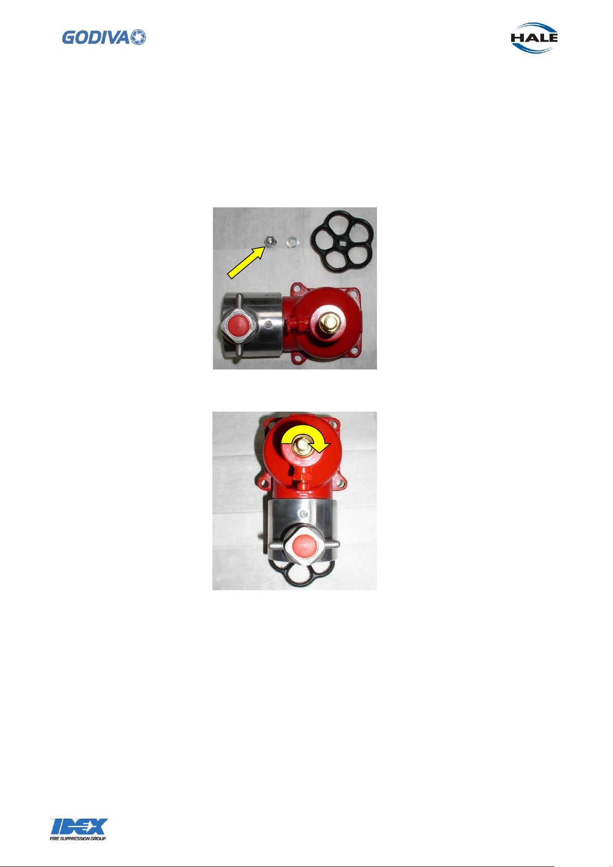
13. Delivery Valve
The delivery valves are removed from the pump manifold by undoing the 4 x M10 nuts
at each corner.
13.1 To inspect and repair the valve, remove the 1 x M10 nut fixing the hand-wheel to
the Spindle.
13.2 Rotate the Spindle Clockwise and remove from the delivery valve housing.
Note: Do NOT attempt to remove the Valve Seal Plate assembly from the Stem
assembly without first removing the Stem assembly from the Spindle. It is not possible
to access the Plate locking nut with a ring spanner with the unit complete.
13.3 Using a suitable chisel, bend the tab away from the Locking Nut and release the
nut to allow the Stem to be separated from the Spindle.
Page 74

73
©Godiva Ltd. Our policy is one of continuous development. We therefore reserve the
right to amend specifications without notice or obligation.
SPINDLE
13.4 Using a suitable chisel, bend the tab away from the Plate Locking Nut and release
the nut to allow the Stem to be separated from the Valve Plate
13.5 Re-assembly is a reversal of the dismantling. Check condition of and renew as
necessary the tab washers.
Renew the spindle O ring inside the valve body.
13.6 Lubricate the Spindle, valve body threads and O Ring with suitable water-proof
grease; Shell Alvania WR2, or similar.
Page 75
74
©Godiva Ltd. Our policy is one of continuous development. We therefore reserve the
right to amend specifications without notice or obligation.
System type
12V negative earth
Alternator
12V 43A, rotor-stator type integrated on
engine PTO-side
Optional belt driven alternator 12V 55A on
MAG side
Starter
bendix engagement, acting onto ring-gear on
generator rotor 1.2kW
Ignition system:
electronically controlled “distributor less”
ignition system
Ignition coil:
coil-on-plug-type, separate coil per cylinder
Spark plug:
Champion RC7 PYCB X
Spark plug gap:
0.7 – 0.8mm
14. Instrument Panel
To remove the instrument panel on top of the pump -
14.1 Undo the 4 x screws retaining the panel to the top of the frame.
14.2 To release the panel from the pump all the wiring harness and pump gauge
components must be disconnected from the panel.
Note where the connections are made to ensure the harness and gauges can be
reconnected correctly. The 4 x panel retaining screws should be replaced with a small
amount of Loctite 243 applied to the thread.
15. Electrical System
The pump and engine electrical system is checked by diagnostic software connected
to the unit through the main wiring harness. Contact Godiva Ltd. or your approved
local distributor for more details concerning the diagnostic software.
Electric system data -
Page 76

75
©Godiva Ltd. Our policy is one of continuous development. We therefore reserve the
right to amend specifications without notice or obligation.
ECU
Synerject M3D
- torque control based EMS with ETC
- knock control
- CAN communication
Sensors, actuators:
Delphi except for
- ETC and coils (Bosch)
- phase sensor (Siemens)
Engine Management System -
15.1 Engine Control Unit
The Engine Control Unit located on the underside of the instrument panel, provides
engine calibration and management according to pre-programmed data and is
accessed by the diagnostic software mentioned above. In normal operation it is not
necessary to access this unit.
15.2 Fuses / Relay
There are two relay units and three fuses located in a waterproof housing immediately
behind the discharge valves
15.3 To replace the fuse or relay. Ensure the battery is disconnected. Remove the
cover to the fuse/relay housing.
15.4 The fuses and relays are a push fit in the housing.
This diagram shows the location and purpose of the fuses and relays
Page 77

76
©Godiva Ltd. Our policy is one of continuous development. We therefore reserve the
right to amend specifications without notice or obligation.
Fuse and Relay Map – note the orientation of the relays is unimportant.
Main relay
Fuel pump
relay
15A
7.5A
15A
Injectors and coil
Ignition
Fuel pump
15.5 Instrument panel lights
To replace the warning lights on the instrument panel.
First undo and lift the instrument panel from the frame, see section 12 Instrument
Panel. It is not necessary to disconnect any of the wiring harness or gauge
connections.
15.6 The warning lights are clipped into the panel. Disconnect the wiring harness from
the light unit to be replaced, note the wiring connection.
15.7 The light units push into the panel from the top side.
Page 78
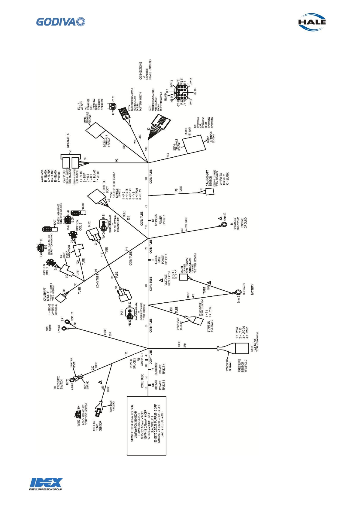
77
©Godiva Ltd. Our policy is one of continuous development. We therefore reserve the
right to amend specifications without notice or obligation.
15.8 Engine wiring harness
Page 79
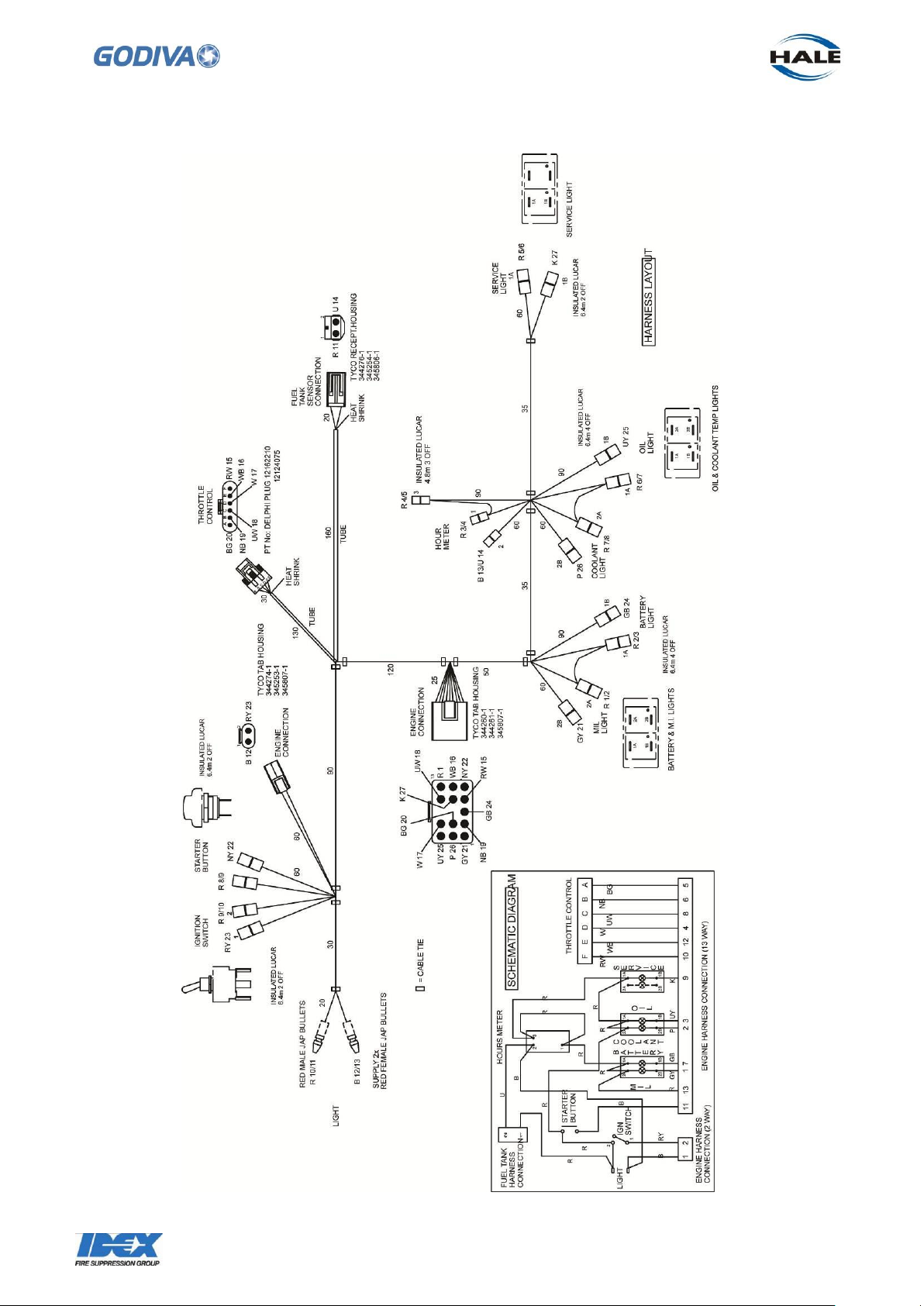
78
©Godiva Ltd. Our policy is one of continuous development. We therefore reserve the
right to amend specifications without notice or obligation.
15.9 Control Panel Wiring Harness
Page 80
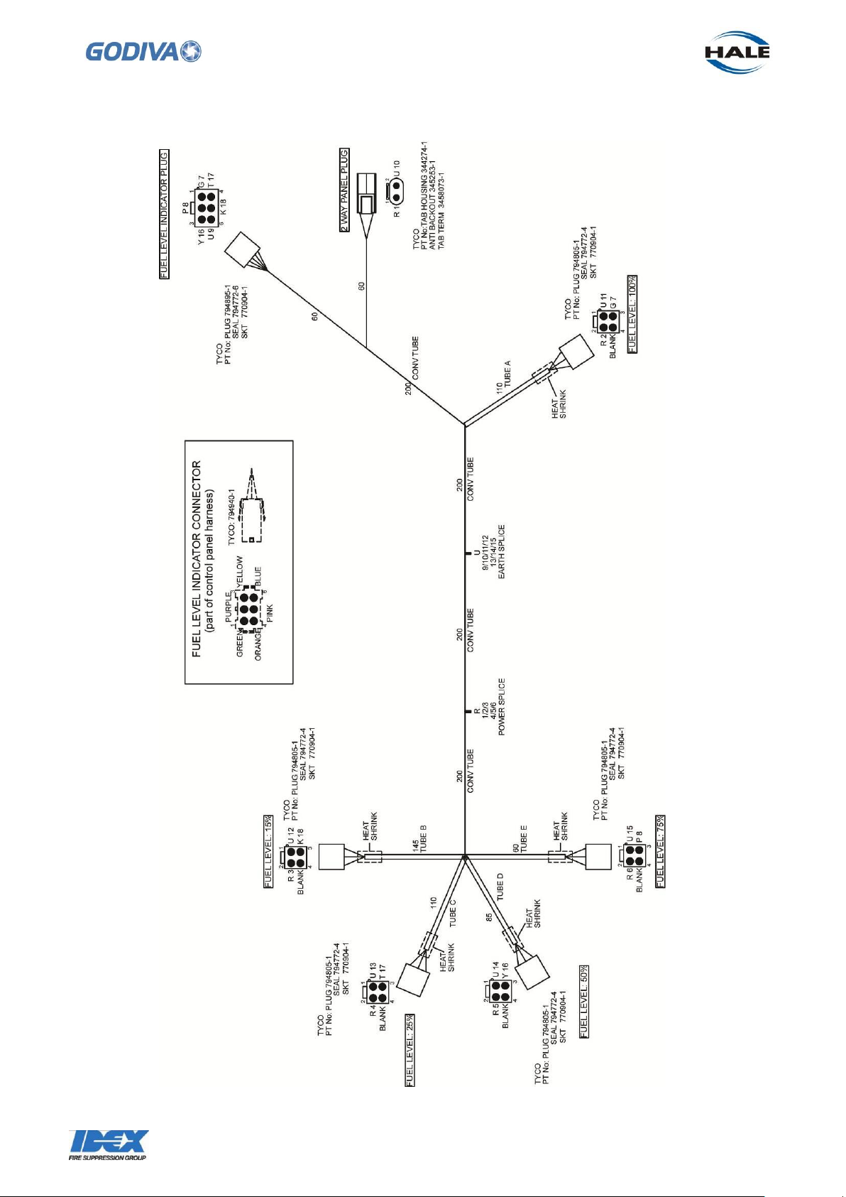
79
©Godiva Ltd. Our policy is one of continuous development. We therefore reserve the
right to amend specifications without notice or obligation.
15.10 Fuel Tank Harness
Page 81
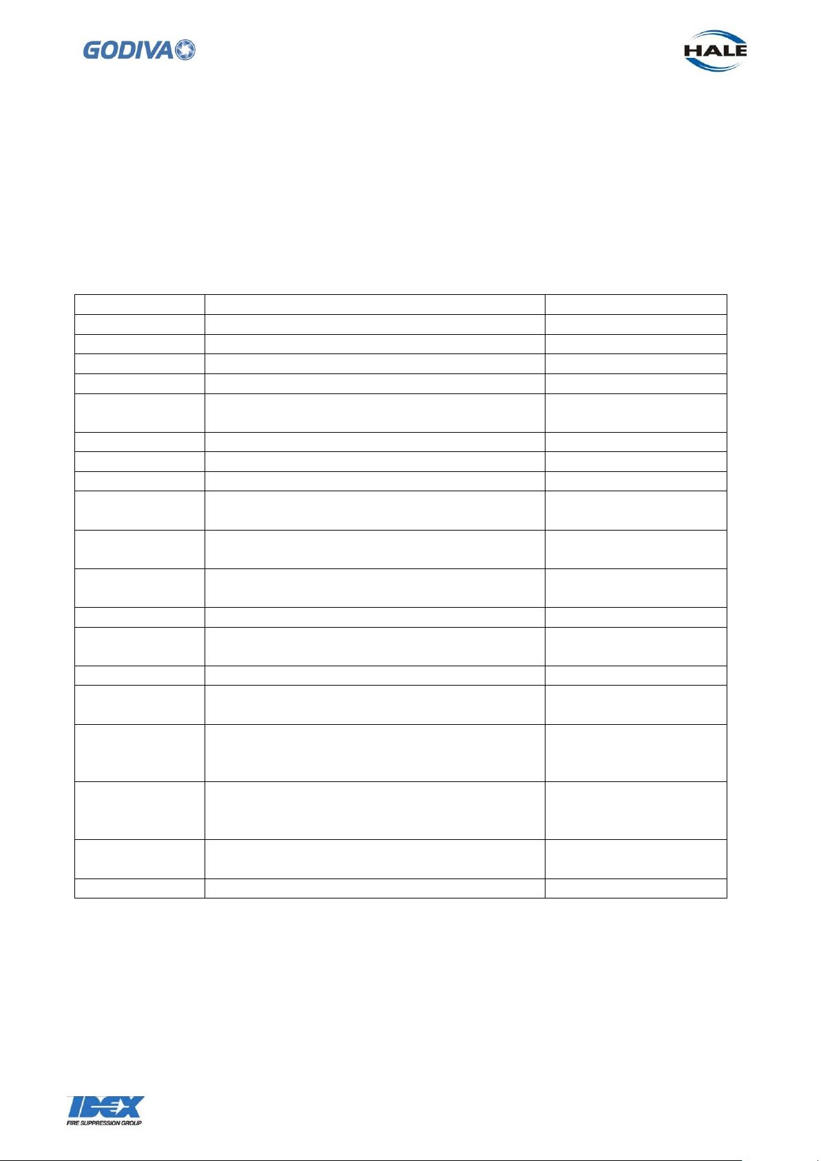
80
©Godiva Ltd. Our policy is one of continuous development. We therefore reserve the
right to amend specifications without notice or obligation.
Page
Location
Adhesive
32
Front wear ring, securing to suction tube
Loctite 243
33
Mechanical seal face cleaning
Loctite 7063
33
Side panel, retaining screws
Loctite 243
34
Rear wear ring, securing to pump head
Loctite243
36
Priming valve, on screw retaining seal
washer to piston
Loctite 243
44
Heat exchanger, retaining screws
Loctite 243
46
Skid plate, retaining screws
Loctite 243
50
Fuel tank, retaining screws
Loctite 243
50
Fuel tank connections – fuel filter, equal tee
Loctite 410 and
Activator 770
52
Stub shaft, on six screws retaining stub
shaft to engine
Loctite 243
52
Stub shaft splines, and corresponding pump
shaft splines
CV grease, or similar
53
Mechanical seal face
Soft soap solution
58
Impeller, rear centre section, inside and
ourside
Soft soap solution or
rubber lube
54, 59
Mechanical seal face cleaning
Loctite 7063
60
Threaded end of pump shaft and inside
impeller centre
CV grease, or similar
70
Delivery valve, spindle, valve body threads,
and O ring
Water proof grease,
Shell Alavania WR2 or
similar
-
If fitting extended handles in place of nonextending handles, spread on inside thread
of new handle and on frame thread
Loctite 638
-
If fitting a new grip to a handle, spread
along handle.
Loctite 410
71
Instrument panel, retaining screws
Loctite 243
16. Engine Maintenance
Refer to the Weber Engine Repair Manual for maintenance procedures relating to the
engine.
17. Adhesives, Solvents and Greases List
The following is a summary of the adhesives, solvents and greases required and the
area of application.
Page 82
81
©Godiva Ltd. Our policy is one of continuous development. We therefore reserve the
right to amend specifications without notice or obligation.
Godiva Limited
A Unit of IDEX Corporation
Charles St
Warwick CV34 5LR
England
Tel:+44 (0)1926 623600
Fax: +44 (0)1926 623666
www.godiva.co.uk
Page 83

406555_RLF
Rev 1.2
11.10.2012
en_English
REPAIR MANUAL
4-Stroke Engine
MPE 850 IND NA
This repair manual is valid for the following engine variants:
– 406555
Read the introductory chapter before performing the task on the engine.
Pay particular attention to the safety messages.
Page 84

Page 85

Weber Motor GmbH strives to make continual improvements as part of the ongoing technical development of
its products. All documentation is therefore subject to technical modifications.
Reprints and translations, in whole or in part, require written permission from Weber Motor GmbH.
All rights reserved according to the copyright law.
Weber Motor GmbH
Otto-Lilienthal-Str. 5
88677 Markdorf
Germany
www.weber-motor.com
Page 86
Table of contents
Table of contents
1 About this document 9
1.1 Meaning of the symbols and signal words.........................................9
1.2 Finding the required information ................................................9
1.3 Change management........................................................10
2 Safety 11
2.1 Meaning of the safety alert symbol and signal words ............................... 11
2.2 Important safety messages ................................................... 12
3 Basic instructions for working on the engine 15
3.1 Before you begin working.....................................................15
3.1.1 Removing engine from portable fire pump ................................. 15
See the portable fire pump manufacturer‘s documentation.
3.2 Lift and transport the engine. ..................................................16
3.3 Mount the engine on the engine stand...........................................17
3.3.1 Mount the engine on the drive side of the engine stand.......................18
3.3.2 Mount the engine across from the drive side of the engine stand ...............19
3.4 While working..............................................................20
3.4.1 Tightening torque ....................................................20
3.4.2 Cleaning ........................................................... 20
3.4.3 Disposal ...........................................................20
3.5 Checking the work carried out .................................................21
4 Tools and accessories 22
4.1 Weber Motor tool case.......................................................22
4.2 Equipment workshop ........................................................23
4.3 Supplies ..................................................................26
010 Crankcase 27
010.01-1 Crankcase............................................................27
010.01-1.01 Replacing crankcase ............................................28
010.01-1.02 Replacing welch plugs...........................................41
010.01-1.03 Replacing tie rod ............................................... 42
010.01-1.04 Replacing plugs................................................43
010.01-2 Crankcase............................................................45
010.01-2.01 Replacing cylinder liners ......................................... 46
010.01-2.02 Replacing oil seal...............................................48
010.01-2.03 Replacing plug.................................................51
010.01-3 Crankcase............................................................52
010.01-3.01 Removing plug.................................................53
010.01-3.02 Installing plug..................................................54
010.01-3.03 Replacing plugs................................................55
010.01-3.04 Removing fitting................................................57
010.01-3.05 Installing fitting.................................................58
4 RLF MPE850 Rev 1.2 | 406555 |
Page 87

Table of contents
010.01-3.06 Removing sensor crankshaft......................................59
010.01-3.07 Installing sensor crankshaft.......................................60
010.02-1 Oil cooler bracket ...................................................... 61
010.02-1.01 Removing oil cooler bracket ......................................62
010.02-1.02 Installing oil cooler bracket .......................................64
010.02-2 Oil cooler bracket ...................................................... 66
010.02-2.01 Replacing blanking cover.........................................67
010.02-2.02 Replacing plug.................................................69
010.02-2.03 Sealing cover oil cooler bracket....................................70
020 Crank drive 75
020.01 Crankshaft ............................................................. 75
020.01.01 Removing crank drive. ............................................76
020.01.02 Installing crank drive. .............................................84
020.01.03 Replacing crankshaft ............................................101
020.01.04 Replacing balance shaft ..........................................102
020.01.05 Removing pistons and con rods ....................................122
020.01.06 Installing pistons and con rods .....................................125
020.01.07 Replacing piston ................................................128
020.01.08 Replacing con rod...............................................131
020.01.09 Checking con rod bearing play .....................................133
020.01.10 Checking main bearing play .......................................136
020.02 Stub shaft.............................................................142
020.02.01 Removing stub shaft.............................................143
020.02.02 Installing stub shaft..............................................145
020.03 Crankshaft cover ....................................................... 147
020.03.01 Removing crankshaft cover .......................................148
020.03.02 Installing crankshaft cover ........................................149
030 Cylinder head 150
030.01 Valve cover............................................................150
030.01.01 Removing valve cover............................................151
030.01.02 Installing valve cover.............................................152
030.01.03 Replacing valve cover............................................153
030.01.04 Removing ignition coils...........................................156
030.01.05 Installing ignition coils............................................157
030.01.06 Removing sensor camshaft .......................................158
030.01.07 Installing sensor camshaft ........................................159
030.02 Cylinder head..........................................................160
030.02.01 Removing cylinder head ..........................................161
030.02.02 Installing cylinder head ...........................................164
030.02.03 Replacing cylinder head ..........................................168
030.02.04 Removing spark plugs ...........................................177
030.02.05 Installing spark plugs ............................................178
030.02.06 Removing switch oil pressure......................................179
030.02.07 Installing switch oil pressure.......................................180
030.02.08 Removing fitting ................................................181
030.02.09 Installing fitting .................................................182
030.02.10 Replacing plugs ................................................183
030.02.11 Mounting camshaft .............................................. 185
See chapter 040.01.01 Replacing camshaft.
5RLF MPE850 Rev 1.2 | 406555 |
Page 88

Table of contents
040 Valve train 186
040.01 Camshaft ............................................................. 186
040.01.01 Replacing camshaft .............................................187
040.01.02 Removing chain tensioner ........................................196
040.01.03 Installing chain tensioner .........................................197
040.01.04 Opening timing chain with chain breaking tool .........................198
040.01.05 Closing timing chain with chain breaking tool..........................200
040.01.06 Removing timing chain ...........................................202
040.01.07 Installing timing chain ............................................203
040.01.08 Replacing timing chain ........................................... 205
040.01.09 Replacing chain rail..............................................210
040.01.10 Replacing chain guide............................................211
040.01.11 Checking valve timing............................................212
040.01.12 Setting valve timing..............................................215
040.02 Rocker arms...........................................................218
040.02.01 Replacing rocker arms ........................................... 219
040.03 Valves................................................................225
040.03.01 Removing valve ................................................226
040.03.02 Installing valve .................................................229
050 Cooling system 234
050.01 Thermostat housing .....................................................234
050.01.01 Removing thermostat housing .....................................235
050.01.02 Installing thermostat housing ......................................236
050.01.03 Removing fitting ................................................238
050.01.04 Installing fitting .................................................239
050.01.05 Removing thermostat ............................................ 240
050.01.06 Installing thermostat ............................................. 241
050.01.07 Replacing sensor coolant temperature...............................242
050.01.08 Replacing plug thermostat housing..................................243
050.01.09 Removing closing cap thermostat housing............................244
050.01.10 Installing closing cap thermostat housing.............................245
050.02 Coolant pump..........................................................246
050.02.01 Removing impeller ..............................................247
050.02.02 Installing impeller ...............................................249
050.02.03 Removing coolant pump..........................................251
050.02.04 Installing coolant pump...........................................253
050.03 Oil cooler ............................................................. 258
050.03.01 Removing oil cooler .............................................259
050.03.02 Installing oil cooler ..............................................260
062 Exhaust system 261
062.01 Mounting exhaust manifold ...............................................261
062.01.01 Instructions for mounting nuts and exhaust gasket......................262
062.01.02 Replacing studs ................................................263
070 Intake area 264
070.01 Intake manifold.........................................................264
6 RLF MPE850 Rev 1.2 | 406555 |
Page 89

Table of contents
070.01.01 Removing intake manifold.........................................265
070.01.02 Installing intake manifold..........................................267
070.01.03 Removing intake manifold bracket .................................. 268
070.01.04 Installing intake manifold bracket ................................... 269
070.01.05 Removing sensor intake manifold pressure/temperature .................270
070.01.06 Installing sensor intake manifold pressure/temperature ..................271
070.02 Mounting throttle body ...................................................272
070.02.01 Removing throttle body...........................................273
070.02.02 Installing throttle body............................................274
070.02.03 Replacing throttle body...........................................275
070.02.04 Replacing rubber mount ..........................................278
080 Engine management system 281
080.01 Engine management components overview .................................. 281
080.02 Engine control unit ......................................................283
See the portable fire pump manufacturer‘s documentation.
090 Starter, generator 284
090.01 Starter ...............................................................284
090.01.01 Removing starter................................................285
090.01.02 Installing starter.................................................286
090.01.03 Replacing starter................................................287
090.02 Generator.............................................................289
090.02.01 Removing generator .............................................290
090.02.02 Installing generator ..............................................293
090.03 Voltage regulator .......................................................296
See the portable fire pump manufacturer‘s documentation.
100 Fuel unit 297
100.01 Fuel rail ..............................................................297
100.01.01 Removing fuel rail...............................................298
100.01.02 Installing fuel rail................................................300
100.01.03 Replacing injector ...............................................301
110 Lubrication system 303
110.01 Dry sump ............................................................. 303
110.01.01 Removing suction pump cover ..................................... 304
110.01.02 Installing suction pump cover ...................................... 305
110.01.03 Replacing suction pump cover ..................................... 308
110.01.04 Removing oil suction pump........................................309
110.01.05 Installing oil suction pump.........................................310
110.01.06 Replacing fitting.................................................311
110.01.07 Removing intermediate gear suction pump............................312
110.01.08 Installing intermediate gear suction pump.............................314
110.02 Oil pressure pump ...................................................... 315
110.02.01 Removing oil pressure pump ......................................316
110.02.02 Installing oil pressure pump .......................................318
110.03 Oil pressure valve.......................................................320
110.03.01 Removing oil pressure valve.......................................321
7RLF MPE850 Rev 1.2 | 406555 |
Page 90
Table of contents
110.03.02 Installing oil pressure valve........................................322
110.04 Oil filter...............................................................324
110.04.01 Removing oil filter ...............................................325
110.04.02 Installing oil filter ................................................326
110.04.03 Removing threaded sleeve ........................................327
110.04.04 Installing threaded sleeve .........................................328
120 Engine mount 329
120.01 Lifting eye.............................................................329
120.01.01 Removing bracket on the drive side .................................330
120.01.02 Installing bracket on the drive side ..................................331
120.01.03 Removing pipe clamp ............................................332
120.01.04 Installing pipe clamp .............................................333
120.01.05 Removing bracket across from the drive side..........................334
120.01.06 Installing bracket across from the drive side...........................335
910 Repair kits 336
910.01 Long block ............................................................ 336
910.01.01 Installing long block..............................................337
Appendix 340
Overview of revisions.....................................................340
Index .................................................................341
8 RLF MPE850 Rev 1.2 | 406555 |
Page 91
1 About this document
1.1 Meaning of the symbols and signal words | …
1 About this document
This repair manual describes how to safely and correctly remove, install and replace engine components.
Observe the following information:
– Read through the service manual before performing any tasks.
– In addition, you will always need the spare parts catalog and portable fire pump manufacturer's
documentation.
– Some figures in this repair manual are general illustrations and may differ from the actual engine.
1.1 Meaning of the symbols and signal words
Item Meaning
NOTICE The signal word NOTICE indicates potential property damage.
Information The signal word Information indicates specific features and recommendations.
These chapters are required for tasks covered in the following chapter.
Tools and supplies required for tasks covered in the chapter.
1.2 Finding the required information
The chapter structure in the repair manual is identical to the chapter structure in the spare parts catalog.
When planning to work on the engine, first identify the corresponding component in the spare parts catalog.
Then identify the required work specification in the table of contents of the repair manual in the same
chapter.
For example: You want to replace the cylinder liners. The cylinder liners can be found in the spare parts
catalog in chapter 010.01-2 Crankcase. Within chapter 010.01-2 Crankcase in the repair manual, you then
find chapter 010.01-2.01 Replacing cylinder liners.
9RLF MPE850 Rev 1.2 | 406555 |
Page 92

1 About this document
1.3 Change management
1.3 Change management
Weber Motor GmbH strives to make continual improvements as part of the ongoing technical development
of its products. You may find that descriptions in the repair manual are changed or amended. All changes are
described in the chapter Overview of revisions.
Observe the following information:
– Always use the most current repair manual from the protected area on our web site
www.weber-motor.com.
– Always print the required chapter and all chapters referred to completely and then destroy the printouts.
10 RLF MPE850 Rev 1.2 | 406555 |
Page 93

2 Safety
2.1 Meaning of the safety alert symbol and signal words
2 Safety
This engine is state-of-the-art and built according to recognized safety-technical regulations. Ignoring the
information in this repair manual may result in personal injury or property damage.
This repair manual is solely intended for use in a workshop authorized by Weber Motor or the portable fire
pump manufacturer. All work on the engine must be performed by appropriately trained personnel.
Before beginning any work, trained personnel authorized to work on the engine must have access to the
complete documentation of the engine. Make sure that trained personnel have read and understand all
introductory chapters and in particular, the chapter on safety.
Observe all generally applicable laws and regulations in addition to the information in this repair manual:
– accident prevention
– environmental protection
– handling of hazardous materials
– personal safety equipment
– traffic laws
2.1 Meaning of the safety alert symbol and signal words
Item Meaning
The safety alert symbol draws your attention to possible dangers.
The signal word WARNING indicates a potentially dangerous situation that may
WARNING
CAUTION
lead to a serious or fatal injury.
The signal word CAUTION indicates a potentially dangerous situation that may
lead to a minor or moderately severe injury.
11RLF MPE850 Rev 1.2 | 406555 |
Page 94

2 Safety
2.2 Important safety messages
2.2 Important safety messages
Work specifications
Malfunctions
Defective components
Checking the work carried out
Spare parts
You endanger the safety of personnel if you do not perform work exactly
as described in this repair manual.
► Only deviate from the work specifications in this repair manual
when prompted to do so by the portable fire pump manufacturer.
► Pay attention to the safety messages in the portable fire pump
manufacturer's documentation.
Engine malfunctions pose a safety risk to personnel.
► Only operate the engine when in perfect condition.
Defective engine components pose a safety risk to personnel.
► Replace defective components.
Work performed incorrectly poses a safety risk to personnel.
► Check the portable fire pump safety each time after working on the
engine. (See chapter 3.5 Checking the work carried out.)
All the components in your engine have been carefully tested and fulfill
strict quality and safety requirements. Externally supplied parts cannot
fulfill these requirements.
► Always use original Weber Motor spare parts.
Add-on parts and modifications
Lift and transport the engine.
Securing the engine Crush injuries due to the engine overturning.
12 RLF MPE850 Rev 1.2 | 406555 |
The consequences of attaching add-on parts and making unauthorized
modifications to the engine are unknown and pose a safety risk to
personnel.
► Modifications and the attachment of add-on parts is only permitted if
approved or instigated by Weber Motor.
Spinal column injury due to incorrect lifting of heavy loads.
► Always use a workshop crane to lift and transport the engine on the
brackets provided. (See chapter 3.2 Lift and transport the engine.)
► Mount the engine to the engine stand before starting any work.
(See chapter 3.3 Mount the engine on the engine stand.)
Page 95

2.2 Important safety messages
Tools and accessories Unsuitable tools and accessories pose a safety risk to personnel.
► Always use tools listed in chapter 4 Tools and accessories.
2 Safety
Engine power supply
Protective equipment Missing protective equipment poses a safety risk to personnel.
Hot engine components
Engine exhaust gases
The engine must be disconnected from the power supply before any work
is carried out. Leaving the engine connected to the power supply poses a
risk to personnel.
► Only reconnect the power supply when prompted to do so by the
portable fire pump manufacturer.
► Pay attention to the safety messages in the portable fire pump
manufacturer's documentation.
► Attach all protective equipment after completing the tasks.
Engine components become extremely hot during operation.
► Do not touch any engine components during operation.
► Switch off the engine and wait until the components have cooled.
Engine exhaust gases contain carbon monoxide (CO). Inhalation of
carbon monoxide can deprive the body of oxygen and result in organ
damage or even death by asphyxiation.
► When operating the engine in enclosed spaces, use exhaust hoses
to direct the engine exhaust gases into the open.
Handling of fuel, engine oil and
coolant
Operating materials pose a health risk.
► Always read the manufacturer's instructions.
► Always wash your hands prior to eating, smoking and using the
toilet as well as at the end of the working shift when working with
operating materials.
Operating materials are hazardous to the environment.
► Never allow operating materials to escape into the groundwater,
water courses or sewage system. Always dispose of operating
materials according to applicable national regulations.
Danger of slipping on spilled fluids.
► Always use a filler neck or funnel when filling components with
operating materials.
► Always clean up any spilled operating materials immediately.
13RLF MPE850 Rev 1.2 | 406555 |
Page 96

2 Safety
2.2 Important safety messages
Fuel
Fuel is highly flammable. Vapors may ignite and cause an explosion.
► Do not smoke in the vicinity of the engine and do not allow naked
flames or sparks near the engine or the fuel system.
► Never fill with fuel while the engine is running.
► Do not start the engine if there is a smell of fuel or you suspect that
fuel is leaking. Have a workshop authorized by Weber Motor or the
portable fire pump manufacturer inspect the engine immediately.
► Fuel on hot surfaces can cause fires.
► Do not extinguish with water. In the event of a fire, use foam, dry
chemical or carbon dioxide extinguishers.
14 RLF MPE850 Rev 1.2 | 406555 |
Page 97

3 Basic instructions for working on the engine
3.1 Before you begin working
3 Basic instructions for working on the engine
3.1 Before you begin working
The following requirements must be met before performing any tasks:
– The engine has been removed from the portable fire pump.
– The engine has been disconnected from the power supply.
– There is no engine oil or coolant in the engine.
– The engine is in original factory condition. You identify the factory condition in the spare parts catalog.
3.1.1 Removing engine from portable fire pump
See the portable fire pump manufacturer‘s documentation.
15RLF MPE850 Rev 1.2 | 406555 |
Page 98
3 Basic instructions for working on the engine
3.2 Lift and transport the engine.
3.2 Lift and transport the engine.
– Workshop crane
WARNING! Spinal column injury due to
incorrect lifting of heavy loads. Always lift the
engine using a workshop crane.
NOTICE! Components can break. Lift the engine
only using the brackets.
1
► Lift the engine using the brackets
.
1
1
16 RLF MPE850 Rev 1.2 | 406555 |
Page 99
3.3 Mount the engine on the engine stand
WARNING! Crush injuries due to the engine
overturning. Mount the engine to the engine
stand before starting any work.
If not otherwise specified in the chapter, mount the
engine on the drive side or across from the drive
side.
1
► Mount the engine on the drive side
the engine stand. (See chapter 3.3.1 Mount
the engine on the drive side of the engine
stand.)
or
of
3 Basic instructions for working on the engine
3.3 Mount the engine on the engine stand
1
► Mount the engine across from the drive side
2
of the engine stand. (See chapter 3.3.2
Mount the engine across from the drive side
of the engine stand.)
2
17RLF MPE850 Rev 1.2 | 406555 |
Page 100
3 Basic instructions for working on the engine
3.3 Mount the engine on the engine stand
3.3.1 Mount the engine on the drive side of the engine stand
– Workshop crane
– Engine stand
WARNING! Spinal column injury due to
incorrect lifting of heavy loads. Always lift the
engine using a workshop crane.
NOTICE! Breakage. Lift the engine only using the
brackets.
1
► Lift the engine using the brackets
.
1
1
► Mount the engine on the engine stand.
Suitable mounting points M10:
2
– Depth of thread
– Depth of thread
– Depth of thread
30 mm
3
32 mm
4
34 mm
2
2
3
4
18 RLF MPE850 Rev 1.2 | 406555 |
 Loading...