

Go!Control 2GIG-CNTRL2, 2GIG-CP2 Operation & User’s Manual
PRINTER’S INSTRUCTIONS:
INSTR,Z-WAVE,2GIG-CP2-345E,V1.9 - LINEAR P/N: 233494 X4 - INK: BLACK - MATERIAL: 20 LB. MEAD BOND WITH 80 LB. WHITE COATED COVER - SIZE: 5.500” X 8.500” - SCALE: 1-1 - FOLDING: ALBUM FOLD - BINDING: SADDLE-STITCH
Wireless Security System
2GIG-CNTRL2
(2GIG-CP2)
Z-Wave Services
Operation & User’s Guide
Congratulations on your ownership of a Go!Control Security System!
This wireless system offers protection for your property against burglary,
protection for yourself and family with 24-hour emergency monitoring, and
optionally fi re and carbon monoxide detection for your home.
With the system’s built-in Z-Wave® home automation capability, you can
control your Z-Wave® enabled household lights, appliances, and door locks
from the Control Panel or from a portable Z-Wave remote controller.
An exciting feature of the Go!Control Security System is the capability to
remotely control your Z-Wave® network of devices from your own computer
using a Web browser over the Internet. This provides you with home
automation control from anywhere in the world... even through your Web
enabled cell phone or PDA! (Web remote control is an optional feature, check
with your security professional for availability with your system.)
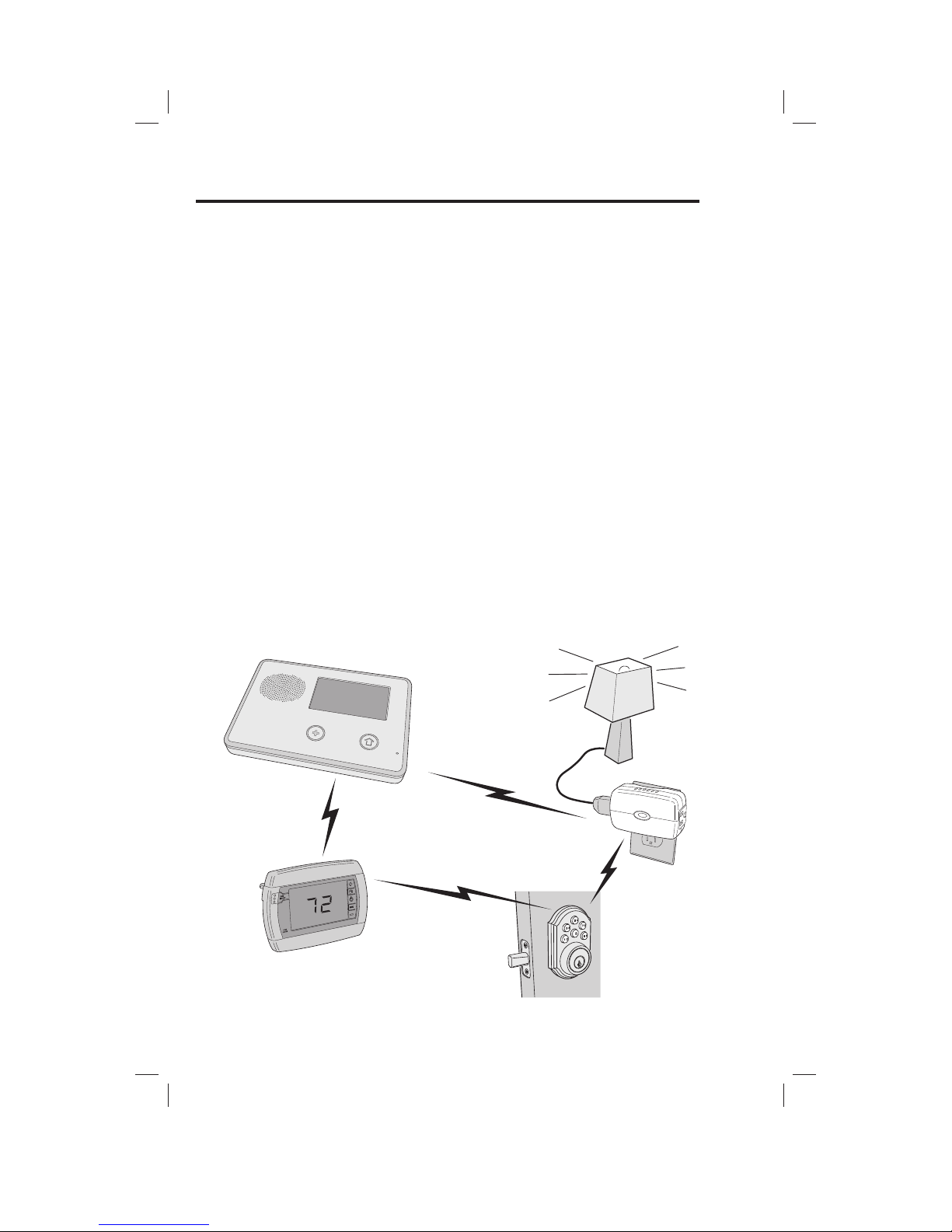
The GO!Control Security System
Typical Z-Wave Network
CONTROL
PANEL
Z-WAVE
THERMOSTAT
Z-WAVE
SWITCH
WIRELESS
NETWORK
SIGNALS
NETWORK SIGNALS TRAVEL
BETWEEN THE CONTROL
PANEL AND Z-WAVE DEVICES
NETWORK SIGNALS ALSO
TRAVEL DIRECTLY
BETWEEN Z-WAVE DEVICES
THE Z-WAVE NETWORK AUTOMATICALLY
ADJUSTS THE NETWORK SIGNAL PATHS
DEPENDING ON SIGNAL CONDITIONS
Z-WAVE
DOOR
LOCK

1
Table of Contents
Home Control Network Overview
The Z-Wave Network . . . . . . . . . . . . . . . 2
Z-Wave Association Reports . . . . . . . . . 2
Services Access
Services Button . . . . . . . . . . . . . . . . . . . . 3
Device Management . . . . . . . . . . . . . . . . 3
Toolbox . . . . . . . . . . . . . . . . . . . . . . . . . . . 3
Network Setup
Adding Devices . . . . . . . . . . . . . . . . . . . . 4
Additional Z-Wave Devices . . . . . . . . 4
Z-Wave Sirens . . . . . . . . . . . . . . . . . . . . 4
Naming Devices . . . . . . . . . . . . . . . . . . . . 5
Basic Operation
Binary Switches . . . . . . . . . . . . . . . . . . . . 6
Multi-level Switches . . . . . . . . . . . . . . . . 7
Viewing Thermostats . . . . . . . . . . . . . . . 8
Controlling Thermostats . . . . . . . . . . . . . 9
Setting the Mode . . . . . . . . . . . . . . . . . 9
Setting the Temperature . . . . . . . . . . . 9
Setting the Fan Mode . . . . . . . . . . . . . . 9
Door Locks . . . . . . . . . . . . . . . . . . . . . . . 10
Auto Disarm . . . . . . . . . . . . . . . . . . . . . 10
Door Lock User Codes . . . . . . . . . . . . 11
Scenes & Rules
Controlling Multiple Devices . . . . . . . . 12
Creating Scenes . . . . . . . . . . . . . . . . . . 12
Z-Wave Switches . . . . . . . . . . . . . . . . 13
Z-Wave Thermostats . . . . . . . . . . . . . 13
Z-Wave Door Locks . . . . . . . . . . . . . . 13
Testing Scenes . . . . . . . . . . . . . . . . . . 13
Editing Scenes . . . . . . . . . . . . . . . . . . . . 14
Changing a Device’s Action . . . . . . . 14
Removing a Device’s Action . . . . . . . 14
Renaming a Scene . . . . . . . . . . . . . . . 14
Running Scenes . . . . . . . . . . . . . . . . . . . 15
Deleting Scenes . . . . . . . . . . . . . . . . . . . 15
Triggering Devices from Events . . . . . 16
Creating Rules . . . . . . . . . . . . . . . . . . . . 16
Editing Rules . . . . . . . . . . . . . . . . . . . . . . 17
Changing a Rule’s Action . . . . . . . . . . 17
Deleting Rules . . . . . . . . . . . . . . . . . . . . 17
Network Maintenance
Removing Devices . . . . . . . . . . . . . . . . . 18
Network Diagnostics . . . . . . . . . . . . . . 19
Checking the Network . . . . . . . . . . . . 19
Advanced Setup
Advanced Toolbox . . . . . . . . . . . . . . . . . 20
Learn Controller . . . . . . . . . . . . . . . . . 20
Reset Controller . . . . . . . . . . . . . . . . . 20
View Controllers . . . . . . . . . . . . . . . . . 21
View All Devices . . . . . . . . . . . . . . . . . 21
Rediscover Network . . . . . . . . . . . . . . 22
Important Information
Limited Warranty . . . . . . . . . . . . . . . . . . 23
FCC Regulatory Information . . . . . . . . . 23
IC Regulatory Information . . . . . . . . . . 23
Radio Compatibility . . . . . . . . . . . . . . . . 23
Index

2
Home Control Network Overview
The Z-Wave Network
Z-Wave® is “interoperable, two-way RF mesh networking technology”. In
plain English, Z-Wave® allows you to remotely control Z-Wave® enabled
devices in your home.
Z-Wave is a registered trademark of Zensys Inc. and/or
its subsidiaries.
Z-Wave enabled devices are remote control modules that lights or appliances
plug into or accessories with built-in Z-Wave capabilities that are designed
to work with all other Z-Wave enabled devices in a home control network.
Some modules can act as a wireless “ repeater” that extends the range of
the system and insures that commands intended for another device in the
network are received.
The wireless range of Z-Wave devices have a standard, open-air, line-of-sight
distance of 65 feet. The actual performance in a home will depend on the
type on construction, amount of metal between devices, and the number of
Z-Wave devices that are repeating the wireless signals.
Beyond simple controlling of a single device, multiple device control
commands can be assigned using a “Scene”. A Scene can be run on its own,
or “ Rules” can be assigned to trigger a Scene after a Control Panel “ event”
such as arming your system or when an alarm occurs.
The Go!Control Security System’s Z-Wave Services is a security enabled
Z-Wave product, and has been designed to operate with Z-Wave certifi ed
binary (on/off) switches, multi-level (dimmer) switches, thermostats, door
locks, remote sirens, and portable controllers available from a variety of
equipment manufacturers.
Z-Wave Association Reports
The Control Panel stores Association reports from Z-Wave devices that are
able to send those reports. These supported devices are not queried for their
settings, resulting in a faster display of the device’s status on the Control
Panel’s screen, especially with battery-operated Z-Wave devices. Storing
Association reports can also improve battery life of the Z-Wave device, due
to the elimination of polling information from these devices.
3
Services Access
Services Button
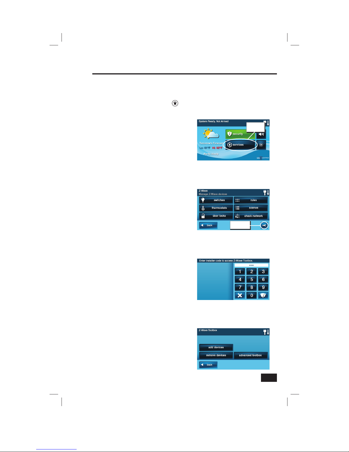
Services are accessed through the system’s Home Screen. The Home Screen shows the system status
with icons to indicate system conditions. It also displays the time and date. The Home Screen displays the
SECURITY and SERVICES buttons. The Home Screen is normally displayed when the system is disarmed. If
it is not currently being displayed, pressing the button on the Control Panel will display the Home Screen.
Device Management
Setup and control of Z-Wave devices is
accessed by pressing the SERVICES button
and using the Manage Z-Wave Devices Screen.
This screen displays buttons for controlling
various Z-Wave devices and a button to access
the Z-Wave toolbox. (Some Services buttons
may or may not display depending on
options selected by your Installer).
• The SWITCHES button will display
the currently included binary
and multi-level switches.
• The THERMOSTATS button will display
the currently included thermostat devices.
• The DOOR LOCKS button will display
the currently included door lock devices.
• The RULES button will display
the currently programmed Rules
that run Scenes after events.
• The SCENES button will display
currently programmed Scenes
that run device actions.
• The CHECK NETWORK button
tests the connection of all
programmed Z-Wave devices.
• The TOOLBOX button allows access
to the Z-Wave toolbox for setup
of devices (requires entry of the
Master User Code, if enabled).
Toolbox
Z-Wave setup is performed using the Toolbox.
Access the Toolbox using the following steps.
1. From the Manage Z-Wave Devices
Screen, press the TOOLBOX button.
2. Enter the Master User Code. If enabled, only
the Master User Code (or the Installer Code)
can be used to access the Z-Wave Toolbox.
✓ NOTE: Some Z-Wave display screens will
time-out after 30 seconds of inactivity and
the system will return to the Home Screen.
Z-Wave Toolbox Screen
Master Code Entry Screen
The Home Screen
Services
button
Manage Z-Wave Devices Screen
Toolbox
button
4
Network Setup
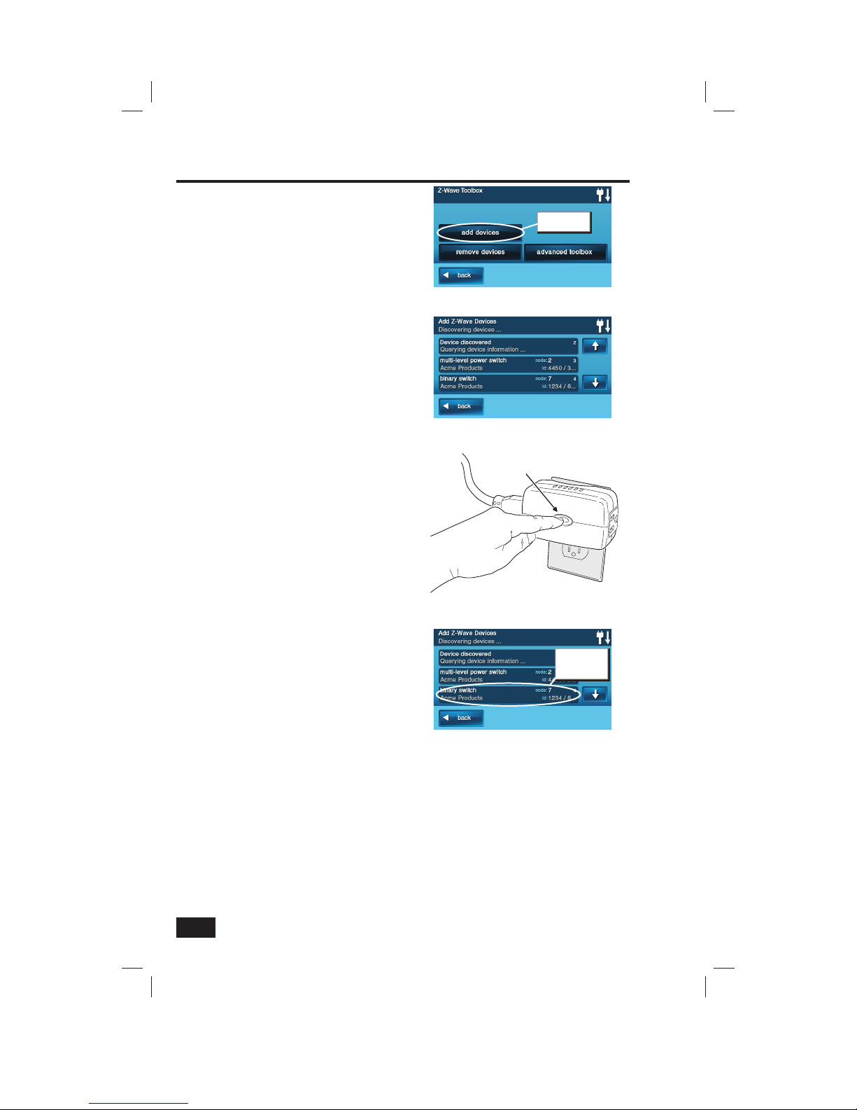
Adding Devices
Before a device will work in the home control
network, it must be added (also called included)
into the network.
To add one or more devices into the network,
use the following steps:
1. Install the Z-Wave Device as directed by the
device’s instructions. If it is a lamp or appliance
module, connect the lamp or load to the module
and be sure the power switch on the lamp or
load is ON.
2. From the Toolbox Screen, press the ADD
DEVICES button. The Control Panel will display
“Discovering devices” and wait for a signal from
a device.
3. Press and quickly release the program button
on the device. (This button may also be called
“bind”, “learn”, or may not be labeled.)
4. When the device is discovered, the display will
show its kind, type, manufacturer, and network
node information assigned to the device.
5. Repeat Steps 3 and 4 for any additional devices
that need to be added to the network at this
time.
6. Press BACK when fi nished.
Additional Z-Wave Devices
If additional Z-Wave compatible devices are
purchased, and your home control network
expands, these steps can be used at any time
to add additional devices.
Devices can only be included once in the
network. The system will not allow a device to
be added multiple times to the same network.
Z-Wave Sirens
Two models of Z-Wave remote sirens are
supported:
• Everspring SE812-2
• FortrezZ 8156A-Z3X
A Z-Wave remote siren will sound when the
Control Panel’s siren sounds. Depending on
setup by your installer, the Z-Wave siren will
sound for burglary, or for burglary and fi re/CO
alarms.
Add Z-Wave Devices Screen
Pressing the Device’s Programming Button
PRESS Z-WAVE
DEVICE BUTTON
Press to add
devices
Z-Wave Toolbox Screen
Added Devices Shown
New device
shows on
screen
✓ NOTE FOR EXISTING INSTALLATIONS:
If Z-Wave devices have been previously
installed and the Control Panel has been
upgraded, to use the Z-Wave Association
feature, remove then re-add all previously
installed Z-wave devices.
5
Network Setup
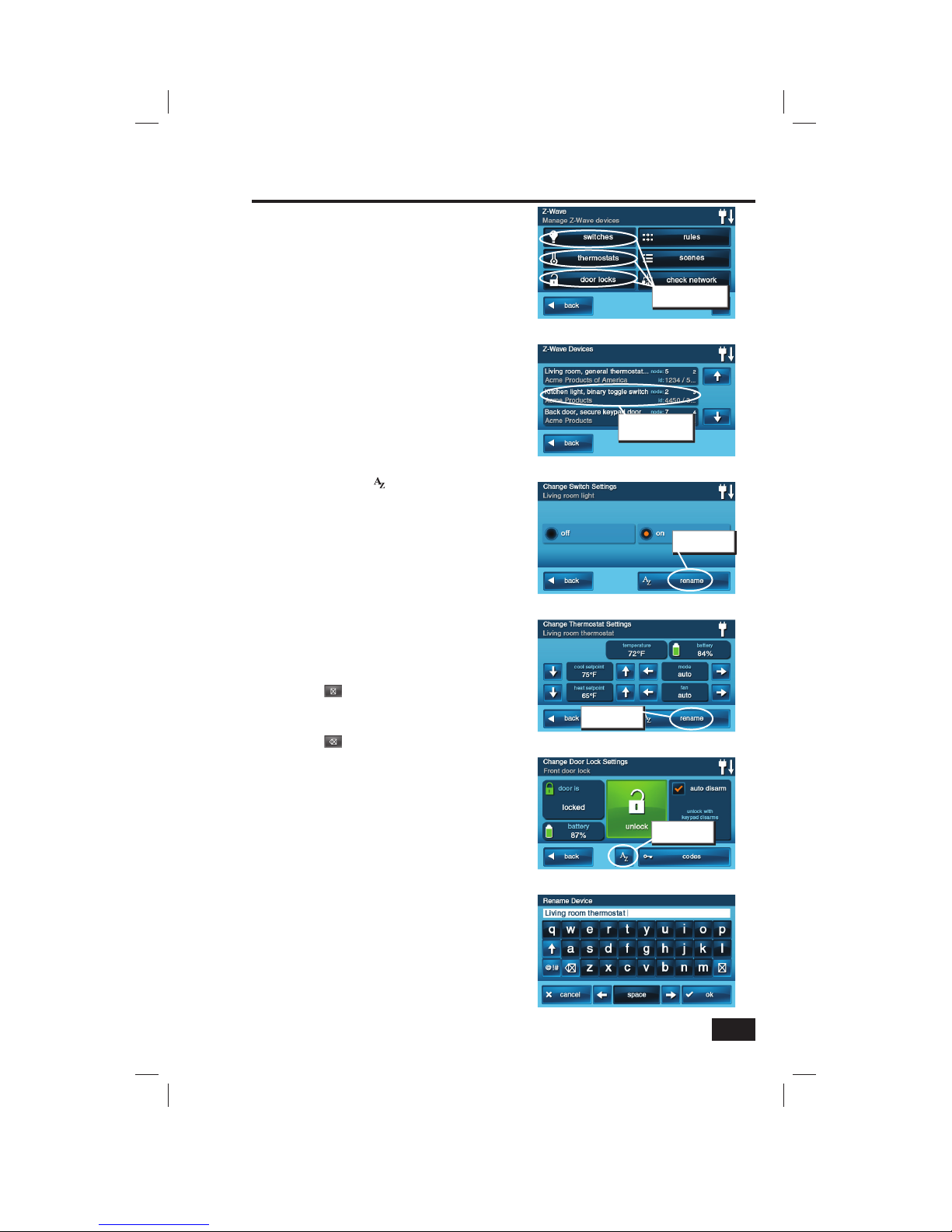
Naming Devices
Devices in the home control network can be
named to make it easy to identify the individual
lamp or appliance being controlled. The custom
name will show on the Control Panel’s display.
To name each installed switch, lock or
thermostat device, use the following steps:
1. From the Manage Z-Wave Devices Screen, press
the SWITCHES, THERMOSTATS, or DOOR
LOCKS button.
2. A list of installed devices will display. If there
are more than three devices, use the ↑ or ↓
arrows to scroll the list.
3. Press the display where the device is listed
to display the current switch settings for the
device.
4. Press the RENAME button to display the
alphanumeric keyboard used to name the device.
5. Use the alphanumeric keyboard to assign a
name (up to 40 characters) to the device.
• Use the ↑ arrow key to shift
to capital letters.
• Use the ↓ arrow key to shift
to lower case letters.
• Press the @!# key to access
numeric and symbol characters.
• Press the abc key to access
alphabetic characters.
• Use the (delete) key to delete
characters to the right of the cursor
or delete highlighted text.
• Use the (backspace) key to delete
characters to the left of the cursor.
• Use the ← or → arrows to move
the cursor along the text.
6. Press OK when you are fi nished naming the
device.
7. Press BACK.
8. Repeat Steps 2 through 7 to name additional
devices.
9. Press BACK when fi nished.
Alphanumeric Keyboard Display
Installed Devices Shown
Push device button
to name
Manage Z-Wave Devices Screen
Press one of the
device types
Switch Settings Display
Push to name
the device
Thermostat Settings Display
Push to name
the device
Door Locks Settings Display
Push to name
the device
6
Basic Operation
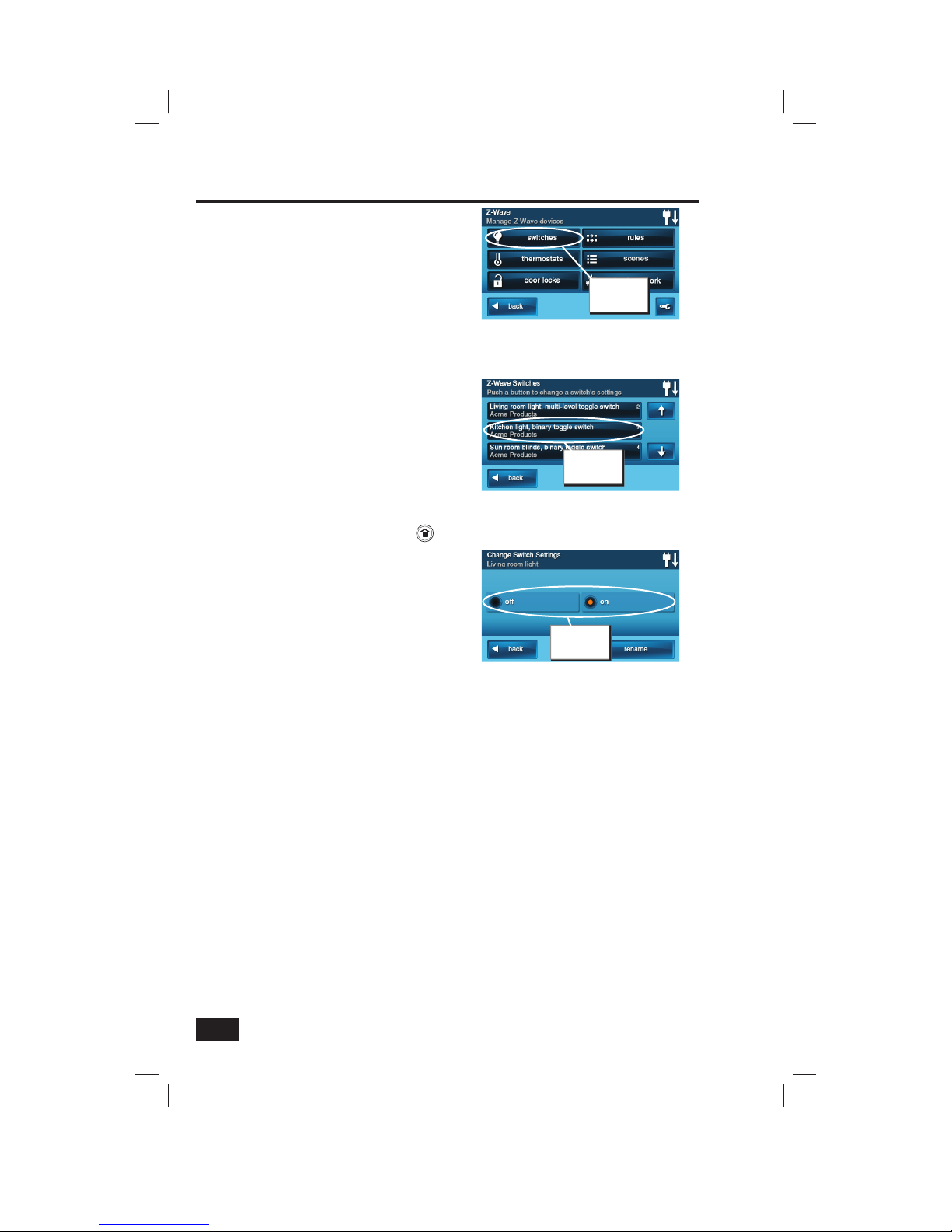
Binary Switches
Binary switch modules can be turned ON or
OFF. They cannot be set to in-between levels as
multi-level (dimmer) switch modules can.
To control a binary switch module, use the
following steps:
1. From the Home Screen press the SERVICES
button.
2. From the Manage Z-Wave Devices Screen, press
the SWITCHES button.
3. A list of all installed switches will be displayed.
If there are more than three switches, use the ↑
or ↓ arrows to scroll the list.
4. Press the display where the device is listed to
display the control buttons for the switch.
5. The display indicates if the switch is OFF or ON.
Press the desired action for the switch (OFF or
ON). The lamp or load connected to the selected
binary switch module will follow your command.
6. Press the BACK button three times or the
button on the Control Panel to exit Services.
Installed Switches Shown
Press device
button
Manage Z-Wave Devices Screen
Press
SWITCHES
button
Binary Switch Settings Display
Select Off
or On
7
Basic Operation
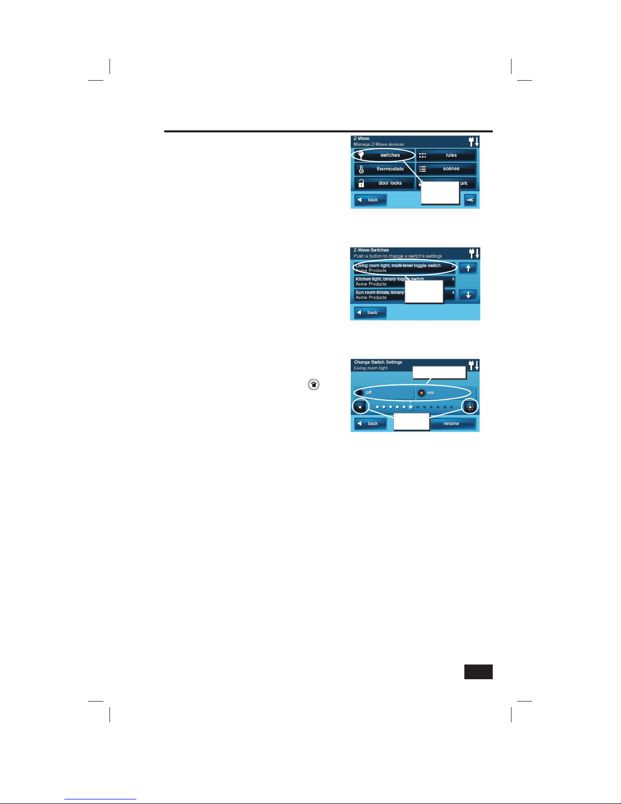
Multi-level Switches
Multi-level (dimmer) switch modules can be
turned ON, OFF, or set to 12 different dimming
levels.
To control a multi-level switch module, use the
following steps:
1. From the Home Screen press the SERVICES
button.
2. From the Manage Z-Wave Devices Screen, press
the SWITCHES button.
3. A list of all installed switches will be displayed.
If there are more than three switches, use the ↑
or ↓ arrows to scroll the list.
4. Press the display where the device is listed to
display the control buttons for the switch.
5. The display indicates if the switch is OFF or
ON. If the switch is ON, the dimming level with
a number 1-12 will be shown below. Press the
desired action for the switch; OFF, ON, or adjust
the dimming level using the brightness buttons
at each end of the dimming level display. The
lamp connected to the selected multi-level
switch module will follow your command.
6. Press the BACK button three times or the
button on the Control Panel to exit Services.
Installed Switches Shown
Press device
button
Multi-level Switch Settings Display
Set device Off or On
Choose
dimmer level
Manage Z-Wave Devices Screen
Press
SWITCHES
button
 Loading...