

Page 1
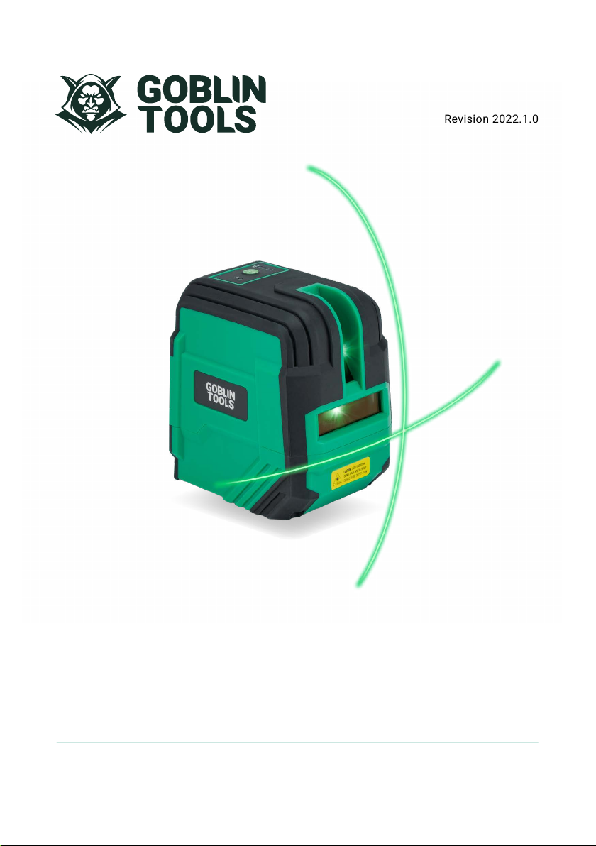
SKU: CLXPG21KT
Revision 2022.1.0
CLX-PG21
Green Beam
Crossline Laser Level Kit
INSTRUCTION MANUAL
Page 2

CONTENTS
SAFETY
ITEM CHECKLIST
LASER OVERVIEW
USING THE LASER
MAGNETIC MOUNT
MOUNTING TO A TRIPOD (NOT INCLUDED)
USING A DETECTOR (NOT INCLUDED)
CARE AND MAINTENANCE
WARRANTY
TROUBLE SHOOTING
CUSTOMER SUPPORT
EU DIRECTIVES AND DISPOSAL
SPECIFICATIONS
3
3
4
4
6
7
7
8
8
9
9
9
9
2
Page 3
SAFETY
Read the following safety instructions before attempting to
operate this tool.
Keep these instructions in a safe place or store in the carry
case for future reference.
SAVE ALL WARNINGS AND INSTRUCTIONS FOR FUTURE
REFERENCE.
WARNING!
!
Read and understand all instructions.
• Use the tool only with the specifically designated
batteries.
• Store the tool out of reach of children and other untrained
persons. Laser tools are dangerous in the hands of
untrained users.
• Use only accessories that are recommended for your
model.
• Tool service must be performed only by qualified repair
personnel. Repairs, service or maintenance performed
by unqualified personnel will void the warranty. Only
approved and authorised service technicians can carry
out warranty repairs.
• Do not use optical tools such as a telescope or transit to
view the laser beam. Serious eye injury could result.
• Do not place the tool in a position which may cause
anyone to intentionally or unintentionally stare into the
laser beam. Serious eye injury could result.
• Do not position the tool near a reflective surface which
may reflect the laser beam toward anyone’s eyes. Serious
eye injury could result.
• Do not use optical tools to view the laser beam.
• Do not set up the tool at a position where the laser beam
can cross any person at head height.
• Do not let children come in contact with the tool.
• Turn the tool off when it is not in use. Leaving the tool on
increases the risk of staring into the laser beam.
• Do not operate the tool around children or allow children
to operate the laser. Serious eye injury may result.
• Position the tool securely on a level surface. Damage to
the tool or serious injury could result if the tool falls.
• Do not remove or deface warning labels.
• If the text on the warning label is not in your native
language, cover it with the appropriate label supplied
before commencing operation of the laser.
WARNING!
!
Do Not Disassemble The Laser.
There are no user serviceable parts inside. Disassembling
the tool will void all warranties on the product. Do not
modify the product in any way. Modifying the tool may
result in hazardous laser radiation exposure.
CAUTION!
!
Class 2 Laser Product
• Never look into the laser beam directly and intentionally.
• Do not use optical tools to view the laser beam.
• Do not set up the tool at a position where the laser beam
can cross any person at head height.
• Do not let children come in contact with the laser.
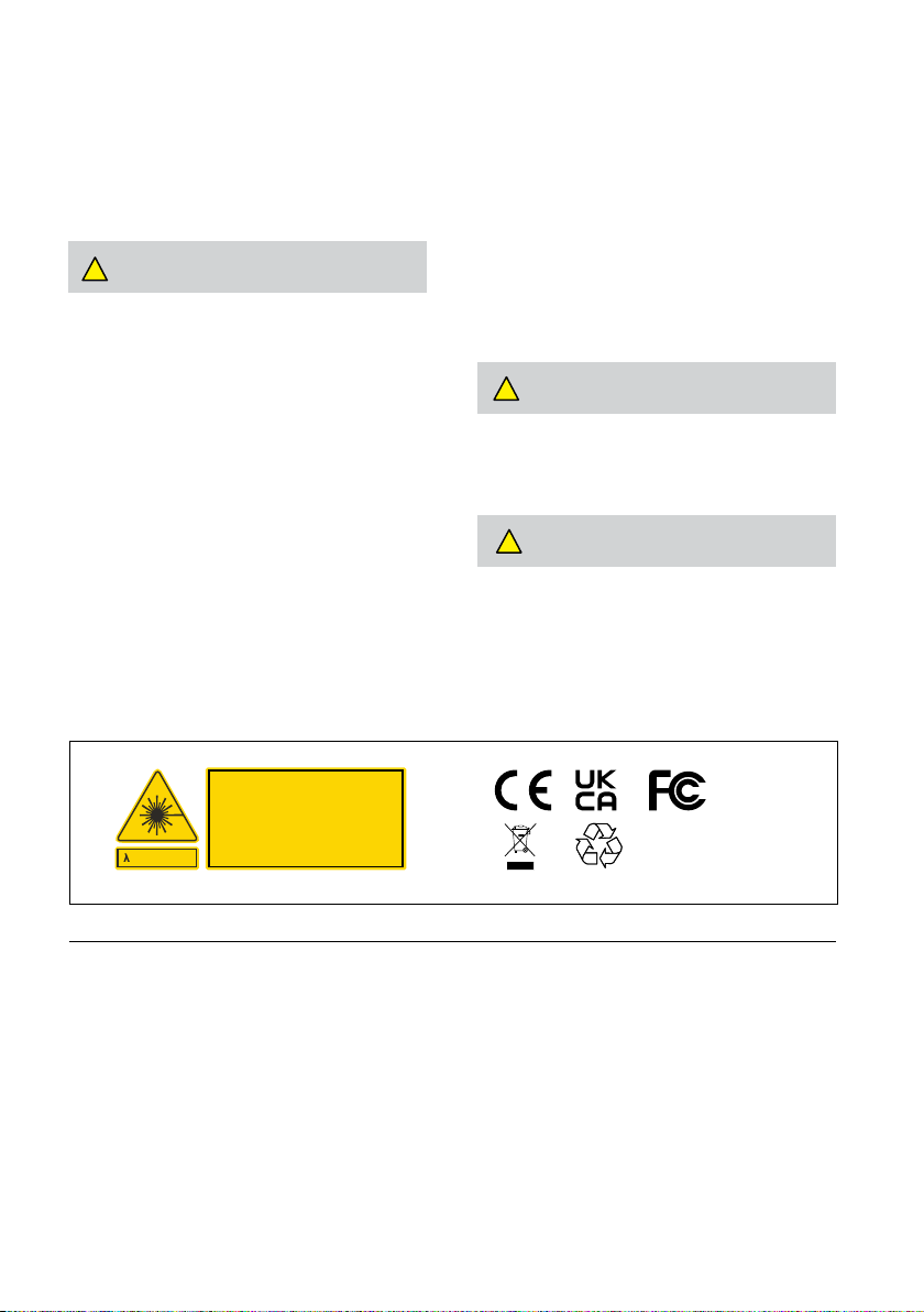
CAUTION
LASER RADIATION!
DO NOT STARE INTO THE BEAM!
CLASS 2 LASER. OUTPUT <1mW
=510-530nm
EN 60825-1:2014
ITEM CHECKLIST
The following items are included with your laser level.
1. CLX-PG21 laser level
2. Magnetic mount
3. Laser target
4. USB-A to USB-C charging cable
5. USB-A charger
7. Hard carry case
Made in
China
3
Page 4
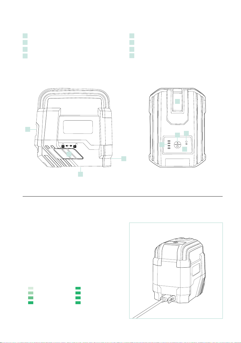
LASER LEVEL OVERVIEW
Laser port
1
2
Control panel
3
Power / locking switch
4
Charging port
1
5
1/4”-20 thread
6
Manual mode / detector (pulse) mode
7
Detector (pulse) mode indicator
8
Power level indicator
1
7
6
8
3
4
5
2
USING THE LASER LEVEL
POWER SUPPLY
• The laser level is supplied with a lithium-ion battery as its
power source.
Charging the battery
Insert the charging cable (USB-C) into the charging port
•
on the laser (Fig.1).
• Insert the charging cable (USB-A) into the power adaptor.
Insert the power adaptor into the power outlet.
• Progress will be shown by the power indicator display on
the laser as below:
Green (flashing):
Battery is charging
• Charging time is approximately 6 hours for a depleted
battery.
4
Green (constant):
Battery is charged
Fig.1
Page 5
SETUP
USING THE LASER LEVEL (continued)
Select a place as close as practical to the work site.
•
Ensure the location is clear of traffic.
• Place the laser on a level surface such as a bench, floor
or mount.
OPERATION
Powering on (self-levelling)
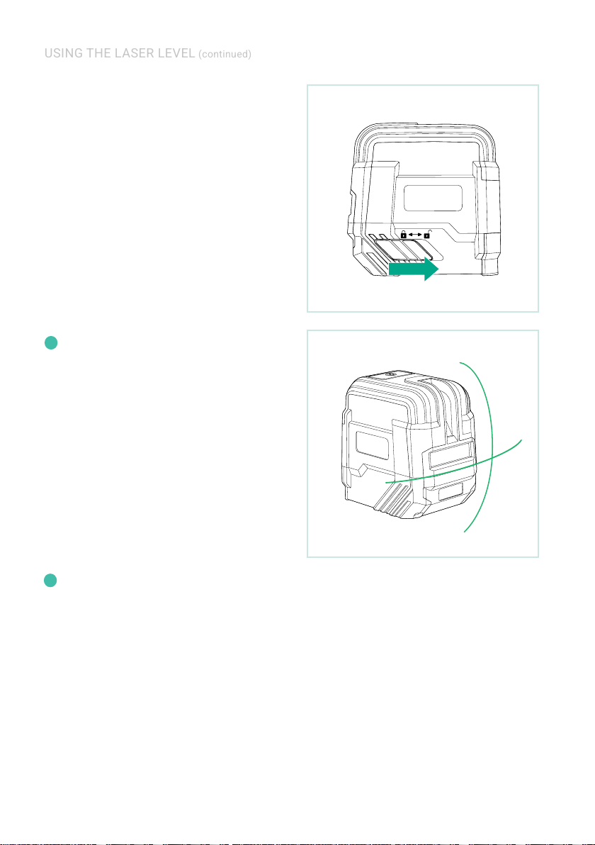
• To turn the laser level on, slide the
to the “unlocked” position (Fig. 2). Self levelling will
commence and the horizontal and vertical beams will
activate (Fig.3).
• If the laser level is outside the self levelling range the
laser level will not level. The laser beam/s will flash
continuously to alert the user that it is outside of its
levelling range. If this occurs, reposition the laser level
onto a level surface until it can level off.
• The included laser target can be used to assist with
visibility of the laser beam in non ideal light conditions.
In bright outdoor conditions, visible distance will
i
be signicantly reduced. For outdoor use, it is
recommended to purchase an optional detector.
power / locking switch
Fig.2
Powering off (self-levelling)
• To turn the laser level off, slide the
to the “locked” position.
Manual mode
• Ensure the
• Press the
• The laser level can now be tilted to the desired angle. The
• To exit manual mode, press and hold the
When in manual mode the laser level will not self level
i
power / locking switch
position.
manual mode
vertical lines will activate.
laser lines will flash every 5 seconds to alert the user that
the laser level is in manual mode.
button
for 2 seconds. The
LED will deactivate.
indicator
and correct for vibrations and/or disturbances.
power / locking switch
is in the “locked”
button. The horizontal and
self-levelling / manual mode
manual mode
Fig.3
5
Page 6
USING THE LASER (continued)
MAGNETIC MOUNT
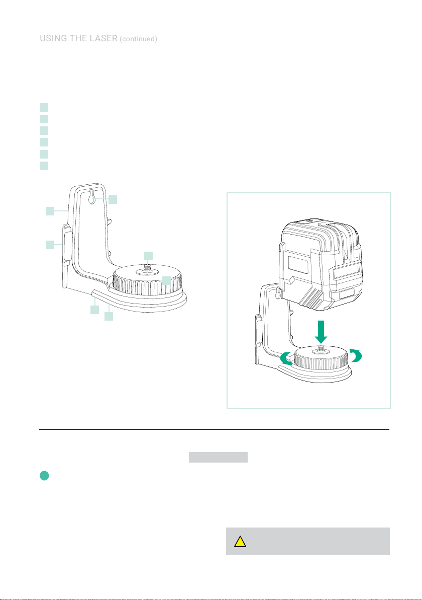
MAGNETIC MOUNT OVERVIEW
1
Magnets
2
Screw fixing point
3
1/4”-20 thread (male)
4
1/4”-20 thread thumb screw
5
5/8”-11 tripod thread (female)
6
1/4”-20 thread (female)
2
1
2
3
4
5
6
USING THE MAGNETIC MOUNT
Mounting onto a magnetic surface
• Attach the laser level to the mount using the thumb screw
(Fig. 4).
• Attach the mount to a metal surface, ensuring that the
mount has a strong hold before releasing your hands.
• To rotate the laser level on the mount, loosen the thumb
screw, position the laser level, and then re-tighten the
thumb screw.
Mounting via screw fixing points
•
Attach the laser level to the mount using the thumb screw
(Fig. 6).
• Fix a screw into a secure surface and hook the mount
over the screw, ensuring that the mount has a strong hold
before releasing your hands.
• To rotate the laser level on the mount, loosen the thumb
screw, position the laser level, and then re-tighten the
thumb screw.
Fig.4
MOUNTING TO A TRIPOD
A tripod can be purchased from your nearest
i
measurement tool dealer. The below instructions are
generic only and set-up methods may vary between
models. Refer to the documentation from the tripod
manufacturer for details.
• Extend the tripod legs to the required height and ensure
the legs are spread wide enough so that the tripod
platform is stable. Secure the legs in place (refer to the
documentation from the tripod manufacturer for details).
• Place the laser level onto the tripod and mount via the
male thread (5/8” or 1/4”) into the base until firm. Do not
over tighten as this may cause damage to the laser level
or tripod.
6
NOT INCLUDED
NOTE: adjustment methods will vary on tripod models.
Always ensure that any locking levers are unlocked before
making adjustments and returned to the locked position
when the adjustment is complete.
• If using an elevating tripod with a measuring scale on the
centre column, the height can be adjusted as required.
WARNING! Attaching the laser to a tripod without
!
the correct thread size may cause damage.
Page 7
USING A DETECTOR
The detector and clamp is an optional accessory used
i
to aid with locating the laser beam in bright conditions.
Please refer to the following information to determine
compatibility when choosing a detector:
Detector type: Green and/or Hybrid.
Green beam lasers are only compatible with detectors
designed to detect a green beam. Hybrid detectors are
designed to detect green or red laser beams.
Frequency: 5000Hz.
The detector must be designed to detect a pulse frequency
of 5000Hz.
Please check with the manufacturer’s specications to
determine compatibility. For more information about
choosing a detector, visit www.goblintradetools.com.
NOT INCLUDED
OPERATION WITH A DETECTOR
• Press the
•
•
•
manual mode / detector mode button
laser level to enter into pulse mode. The
indicator LED
dim when detector mode is activated.
Power on the detector (refer to the documentation
provided by the manufacturer).
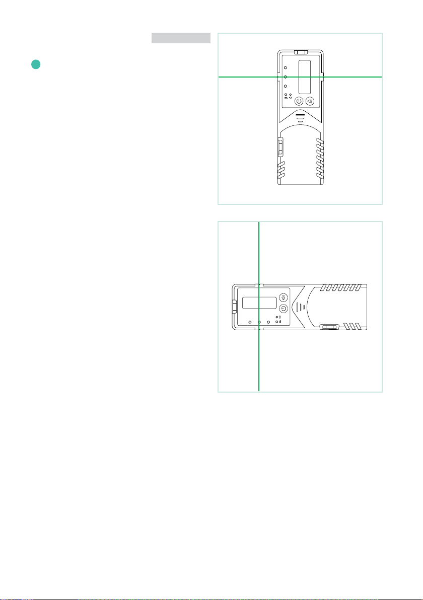
Hold the detector upright for horizontal beams (Fig. 5).
Rotate the detector 90° for vertical beams (Fig. 6).
Move the detector until alignment with the laser beam
is achieved. Detector functions vary between models.
Please refer to the documentation provided by the
manufacturer for details on the operation of the detector.
will activate. The laser beams will appear to
on the
detector mode
Fig.5
Image is for illustrative purposes only.
Fig.6
Image is for illustrative purposes only.
7
Page 8

CARE & MAINTENANCE
1. This is a precision measuring tool and should always be
handled with care and transported within the carry case
provided.
2. Always turn the laser level off when transporting the laser
level or moving around the job site.
3. Whenever possible, store the laser level in a dry, shady
location.
4. Calibration of the laser level is recommended: every six
months, if ongoing accurate levelling is required, or an
impact has occurred.
WARRANTY
5. The operator should check the accuracy of the tool before
precision levelling is attempted. Failure to do so may
result in inaccurate measurements.
6. Clean the laser level with a dry, soft cloth after use in
dusty, damp or wet conditions before storing.
7. Smudges and fingerprints may be removed with a damp
tissue or a soft, lint-free cloth.
All Goblin Tools measurement tools are carefully checked
and tested to our precise quality assurance standards.
We offer a warranty in accordance with the following
conditions:
1. Our warranty provides the correction of deficiencies to
the tool once verified by an authorised service centre that
the deficiencies were caused by a manufacturing fault
within the warranty period.
2. The standard warranty period is 4 years from the date of
purchase. The warranty period can be extended to 8 years
upon registration of the tool within 30 days of purchase.
3. The warranty does not cover:
a) Calibrations and components that are subject to wear
and tear.
b) Defects in the tool caused by non-compliance with
the operation instructions, improper use, abnormal
environmental conditions, inappropriate operating
conditions or insufficient maintenance.
c) Defects caused by using accessories or spare parts
other than approved parts.
d) Services or repairs carried out by non-authorised
persons.
4. Defects recognised by an authorised service centre as
being covered by the warranty shall be corrected either by
repair or replacement of the tool.
5. The warranty claim must be lodged within the warranty
period. This requires the complete tool with the original
sales receipt containing the purchase date and place
of purchase. Partial or disassembled tools cannot be
submitted for a warranty claim.
6. Services provided under warranty do not lengthen or
renew the warranty of the tool.
The above guarantees apply to tools that are
purchased in the countries and regions specified
online at www.goblintradetools.com
4 YEAR STANDARD WARRANTY PERIOD
1. The warranty period for your tool is 4 years from the date
of purchase.
2. The warranty period for batteries, battery packs and
chargers is 1 year from the date of purchase.
3. Calibrations are not covered under warranty as they are
deemed wear and tear.
4. All products have a standard warranty period, you do not
have to register your products to obtain the standard
warranty period.
5. To claim under this warranty, the date of purchase of the
tool must be documented by an invoice/receipt.
8 YEAR EXTENDED WARRANTY PERIOD
1. The extended warranty is available on selected tools only.
2. You may extend the warranty period for your tool (laser
level, optical level or laser distance measurer) to 8 years
from the date of purchase. Accessories are excluded from
the warranty extension and remain at the 4 year warranty
period.
3. The warranty period for batteries, battery packs and
chargers is 1 year from the date of purchase.
4. Calibrations are not covered under warranty as they are
deemed wear and tear.
5. To obtain the extended warranty, the registration process
must be completed within 30 days from the date of
purchase.
6. Failure to register your product online and/or submission
of a valid invoice/receipt will void the warranty extension.
7. Please ensure ALL information submitted/uploaded is
correct.
Extended warranty is ONLY available via online registration,
offline (mailing in of warranty registration) will not be
accepted.
Visit www.goblintradetools.com to register.
8
Page 9

TROUBLE SHOOTING
Error Cause & Solution
Laser does not turn on
• The battery pack may require charging or need to be replaced due to age and / or a
high number of charging cycles.
Laser does not remain on
for long periods of use.
Laser does not level off
Battery pack will not charge or
is not lasting long in use
• The battery pack may require charging or need to be replaced due to age and / or a
high number of charging cycles.
• The laser level may be outside its self levelling range and may require an
adjustment before self-levelling can commence.
• The laser level may have impact damage.
• The battery pack may require charging or need to be replaced due to age and / or a
high number of charging cycles.
CUSTOMER SUPPORT
To assist you with any queries or technical
questions please contact customer support.
United Kingdom: 0808 189 1152
All other countries / regions:
Visit www.goblintradetools.com for more information
Registered Business Address:
98 Middlewich Road, Northwich,
Cheshire, CW9 7DA United Kingdom
RESPONSIBLE DISPOSAL
Please do not throw any electrical e quipment (including
those marked with the c rossed out wheeled bin symbol)
in your bin.
This device complies with all necessary standards for the
free movement of goods within the EU. This product is an
electric device and must be collected separately for disposal
according to the European Directive on waste electrical and
electronic equipment.
SPECIFICATIONS
Specications CLX-PG21
Product code CLXPG21KT
Warranty 8 Years*
Accuracy ±2mm at 10m
Operating range (indoors) 30m (98ft)^
Levelling range ±3°
Laser class 2 Green
Battery life 12 hours
Battery type
Vertical lines 1
Horizontal lines 1
IP rating 54
Weight (g) 298
Dimensions (mm) 86 x 62 x 90
*With online registration (4 years without registration).
Please refer to page 8 for details.
^ Maximum operating range can only be achieved indoors in
ideal light conditions.
(±1/10in / 0.06in at 30ft)
12V 2000mAh
Li-ion battery (internal)
Whilst every attempt is made to ensure the accuracy of all information within
this instruction manual, Spot-on Laser & Tool Company UK Ltd reserves the
right to correct errors or omissions at any time.
9
Page 10

NOTES
10
Page 11

NOTES
11
Page 12

© 2023 Spot-on Global Group Ltd. Goblin Tools is a trademark of Spot-on Global Group Ltd
and is used under license by Spot-on Laser & Tool Company UK Ltd. All Rights Reserved.
 Loading...