

Page 1

ESCAPE REMOTE
WIRING KIT
INSTALL GUIDE
Page 2
IMPORTANT SAFETY INSTRUCTIONS
This system must be installed by a professional. Contact your local van or RV
dealership for local installer recommendations.
The cables in each kit must be properly integrated into the RV/Trailer electrical
system; improper installation will prevent the Goal Zero customer support team
from accurately troubleshooting integrated Goal Zero products.
SAVE THESE INSTRUCTIONS
Please read all warnings, instructions, and cautions carefully before use to
avoid personal injury, property damage, or damage to your product or any
connected products. Goal Zero reserves the right to update this document
without prior notice. Please visit www.goalzero.com to find the latest
product information and the most recent version of the User Guide.
BEFORE YOU BEGIN
Ensure you have the proper kit for the type of recreational vehicle you are
installing the Escape system in. For Drivable vehicles (RVs, Sprinter Vans, etc.),
you will need a different kit than for Towable vehicles (trailers, toy haulers, etc.).
The Escape Remote Wiring Kit is intended to fully replace the existing OEM
power system.
For assistance with your device in the United States, visit our contact page at
www.goalzero.com/contact or call 1-888-794-6250. For assistance with your
device outside of the United States, contact the local distributor. If you do not have
contact information for the local distributor, contact us in the United States and we
will help connect you to the local representative.
For Drivable vehicles, you can choose to install the (AC) TT-30 Cable that takes
AC power to outlets via the AC breaker box. Alternatively, you can choose to
install the Power+ Cable (SKU 98755, sold separately) to increase the charge
rate of your Yeti PRO 4000 and recharge via shore power. Please refer to the
kits below. For a complete list of all cables, please refer to the Cable chart at the
beginning of this guide.
Page 3
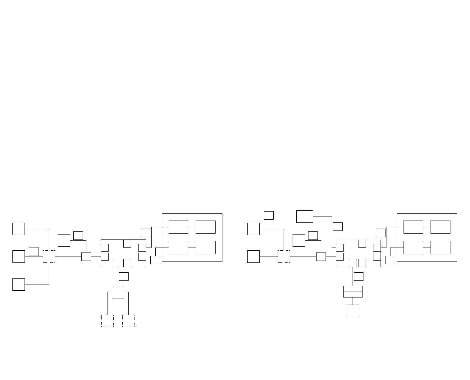
DRIVABLE VEHICLE KIT
TOWABLE VEHICLE KIT
• SKU 98730 -
Flying Leads to Solar HPP+ Input Cable (12 V power into Yeti PRO 4000)
• SKU 98735 -
12 V Locking HPP to Flying Leads Output Cable (12 V power from Yeti
PRO 4000 to vehicle)
• SKU 70035 -
Escape Remote Display HPP+ Power and Data Adapter (Signal Splitter)
• SKU 98082 -
Escape Remote Display Data Cable (CAT-5 Cable 1 to 1 Patch Cable)
• SKU 98765 -
TT-30 to Flying Leads Output Cable (AC power from Yeti PRO 4000 to
vehicle)
• SKU 98775 - Flying Leads to 8 mm DC Input Cable
VEHICLE ALTERNATOR DIAGRAM
W SOLAR
Rooftop
Solar
HPP+
Bulkhead
70040
Alternator/
Vehicle
Battery
HPP+ to
pigtail
98730
3 to 1
Combiner
70030
Screen
70045
Comms to
Screen
Cable
Comms
Splitter
70035
Yeti AC
HPP+
TT-30 to
pigtail
98765
USB
Out
Yeti AC
In
Yeti
8 mm
In
8mm to
flying lead
98775
MC4 2:1
Combiner
Out
12 V
HPP out to
Out
pigtail
QS10
98735
AC Main
Breaker
DC Fuse Block
AC Breakout
Breakers
Control Panel
with Switches
• SKU 98730 -
Flying Leads to Solar HPP+ Input Cable (12 V power into Yeti PRO 4000)
• SKU 98735 - 12 V Locking HPP to Flying Leads Output Cable (12 V
power from Yeti PRO 4000 to vehicle)
• SKU 70035 -
Escape Remote Display HPP+ Power and Data Adapter (Signal Splitter)
• SKU 98082 -
Escape Remote Display Data Cable (CAT-5 Cable 1 to 1 Patch Cable)
• SKU 98765 - TT-30 to Flying Leads Output Cable (AC power from Yeti
PRO 4000 to vehicle)
• SKU 98775 - Flying Leads to 8 mm DC Input Cable
• SKU 98760 - Flying Leads to Power+ Cable
• SKU 70040 - HPP+ Solar Bulkhead Inlet
SAMPLE TOWABLE DIAGRAM
BASE
HPP+ to
Rooftop
Solar
HPP+
Bulkhead
70040
pigtail
98730
3 to 1
Combiner
70030
Screen
70045
RV Plug
Comms to
Screen
Cable
Comms
Splitter
70035
Reunion to
pigtail
98760
Yeti AC
HPP+
In
8 mm
In
flying lead
7 Pin Connector
7 Pin Connector
Yeti
8mm to
98775
AC Main
TT-30 to
pigtail
98765
USB
Out
Yeti AC
Out
12 V
HPP out to
Out
pigtail
QS10
98735
Breaker
DC Fuse Block
AC Breakout
Breakers
Control Panel
with Switches
MC4 2:1
Combiner
100 W Panel100 W Panel
Page 4
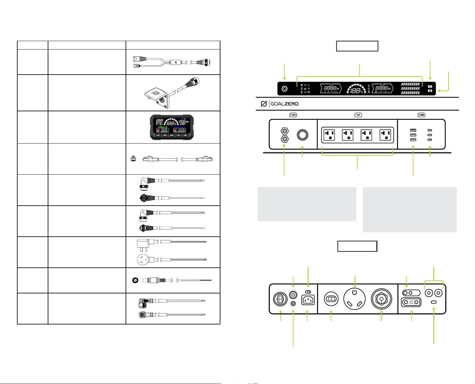
YETI PRO FACE PLATECABLES
SKU NAME VISUAL
70035
Escape Remote Display HPP+
Power and Data Adapter
70040 HPP+ Solar Bulkhead Inlet
70045 Escape Remote Display Unit
98082
98730
98735
Escape Remote Display
Data Cable
Flying Leads to Solar HPP+
Input Cable
12 V Locking HPP to Flying
Leads Output Cable
FRONT INTERFACE
On/Off
Button
12V Cig
Output
12V 6mm Output (10A) x 2
*DISPLAY BUTTON FUNCTIONS
Quick Press: Turn the display screen lights on or off.
Long Press: Turn Blackout mode on or off. In
Blackout mode your Yeti keeps working like normal,
but all status lights will turn off.
Display
AC Outputs x 4
**SETTINGS BUTTON FUNCTIONS
Display
On/Off*
Settings
Button**
USB-C x 3
USB-A x 3
Quick Press: Cycle through menu and info pages
Long Press: Select and enter a menu
• Quick press to go through menu items
• Long press to select menu items
Quick Double Press: Exit Menu or return to
previous screen
98765
98775
TT-30 to Flying Leads
Output Cable
Flying Leads to 8mm DC
Input Cable
98760 Flying Leads to Power+ Cable
BACK INTERFACE
Input Limit
Switch
Input
Breaker
High Voltage
DC Input
Low Voltage
DC Input
AC Input 12V HPP Power+ Expansion
AC Output
Ground30A RV
Output
Breakers
BT/WiFi
Pairing
Page 5

Table of Contents
Escape Kit Mounting Plate Installation 2
Disconnecting the OEM RV/Trailer Power System
Setting up Power IN
Connecting to Shore Power:
Flying Leads to Power+ Cable Installation
Connecting to 12V Power:
Flying Leads to Solar HPP+ Input Cable Installation
Connecting to Solar:
Flying Leads to Solar HPP+ Input Cable Installation for
Portable or Mounted Solar Installation
Connecting to Alternator or Trailer 7-Pin:
Flying Leads to 8 mm DC Input Cable Installation
Setting up Power OUT:
(AC) TT-30 Cable to AC Breaker Panel:
TT-30 to Flying Leads Output Cable Installation
12 V Power to DC Breaker Panel:
12 V Locking HPP to Flying Leads Output Cable
Installation
Escape Remote Display Installation
Page 6
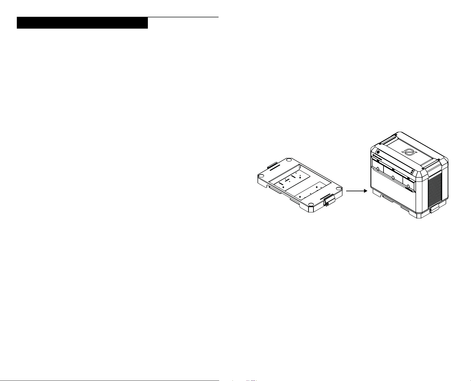
Escape Kit Mounting Plate Installation
Installing the Yeti PRO 4000 in your vehicle or RV requires installation of the
Escape Kit Mounting Plate (SKU 96115). The Mounting Plate keeps the power
station secure and stationary during transport.
NOTE: It is important to install the Mounting Plate in a safe location utilizing the
proper hardware and backing washers to avoid damage to your Yeti PRO 4000.
REQUIRED TOOLS:
• Measuring Tape
• Marking Tool (Paint Pen, Marker, Pencil)
• Power Drill (Cordless/corded)
• Drill Bit M4 / 4 mm Drill Bit
• Wrench Set
- Hex Head (Allen Wrench), 5 mm
- 10 mm Socket
REQUIRED HARDWARE:
• Escape Kit Mounting Plate
• Escape Kit Mounting Hardware
(Refer to the Mounting Plate Install Guide for hardware suggestions)
4. Include sufficient space around the Mounting Plate and install in a direction
that allows the latches to be open and closed.
5. Using a power drill, drill the marked mounting hole locations.
6. Insert Mounting Plate fasteners. Tighten until secure.
7. Attach the Yeti PRO 4000 to the Mounting Plate and verify the unit is secure
before transporting.
INSTALLATION:
Mounting Plate for the Yeti PRO 4000 or Tank PRO 4000
1. Choose an enclosed area and measure its dimensions to ensure there is
enough room for the Mounting Plate (22” X 14” X 16.46”). If you plan to
expand your system in the future with a second Yeti PRO 4000, leave
enough space for an additional Mounting Plate next to the spot you choose.
2. If you are not using the Escape Remote Display Screen, make sure the Yeti
PRO 4000 is mounted so that the power station’s screen is easily accessible
and visible.
3. Mark mounting hole locations that will be drilled out to support installation of
hardware. Make sure the hardware mounting location will not interfere with
vehicle/trailer systems and ensure that all fasteners can be clearly accessed.
2 3
Page 7

Disconnecting OEM RV/Trailer Power System
Setting Up Power In
To change your system from the OEM power system to the Yeti PRO 4000
system, you must first disconnect the existing batteries from the RV/Trailer
circuit.
1. Locate RV/Trailer batteries and disconnect the cables.
a. Disconnect the black Negative (-) ground cable from the Primary Battery
(RH).
b. Disconnect the black Negative (-) ground cable from the Secondary
Battery (LH).
c. Disconnect the red Positive (+) cable from the Primary Battery (RH), then
wrap insulation material around it.
d. Disconnect the red Positive (+) cable from the Secondary Battery (LH).
2. Once the RV/Trailer batteries are disconnected, locate and isolate the AC
TT-30 bulkhead outlet, or “Shore Power.” This will be easily located on the
outside of the trailer.
NOTE: Access to this outlet might be difficult to reach from the inside of the
trailer.
3. Locate the AC Breaker box. This can be traced from the shore power inlet or
may be marked like a home breaker panel.
CONNECTING SHORE POWER TO THE YETI PRO
DRIVABLES RVVAN TOWABLES TRAILERS
Flying Leads to Power+ Cable
The Power+ Cable should be wired up to the TT-30 bulkhead. This allows your
Yeti PRO 4000 to recharge faster. This bulkhead plug would normally be wired
into the AC breaker box providing power across the breaker box to the AC circuit.
With the addition of the Power+ Cable, the 30-amp breaker can be removed and
the Power+ Cable can be wired directly to the TT-30 bulkhead. A 30-amp breaker
can still be used for added protection if separated from the AC TT-30 AC line that
will be wired into the AC circuit from the back of the Yeti PRO 4000.
REQUIRED TOOLS:
• Multimeter
• Wrench Set (Metric/Standard)
• Phillips-Head Screwdriver
• Flat Head Screwdriver
• Hex Key Wrench Set
• Wire Strippers
• Zip Ties
4. The Flying Leads to Power+ Cable (SKU 98760) can be wired directly to the
AC TT-30 bulkhead outlet, or it can be connected to 30 A breaker terminals
(If connecting to the 30 A breaker terminals, be sure the 30 A breaker is not
supplying power to AC circuit).
NOTE: Flying Leads Cables are color-coded. Black is live, White is neutral,
and Green is ground. Match the wiring accordingly. The shore power
bulkhead pass through is the recommended terminal attachment.
5. Do not reconnect the RV/Trailer batteries. The Yeti PRO 4000 replaces the
OEM trailer power system.
4 5
REQUIRED HARDWARE:
• Yeti PRO 4000
• Flying Leads to Power+ Cable (SKU 98760)
INSTALLATION:
1. Refer to the steps listed in the “Disconnecting OEM RV/Trailer Power
System” section (Page 4).
2. Locate the AC Breaker box. This can be traced from the shore power inlet.
3. Connect directly to the trailer bulkhead. This may be a TT-30 but can also be
an L5-30 or other manufacturer-preferred bulkhead to connect shore power.
4. The Flying Leads to Power+ Cable can be connected to the shore power
Page 8
bulkhead. The shore power bulkhead pass-through is the recommended
terminal attachment.
NOTE: Flying Leads Cables are color coded. Black is live, White is neutral,
and Green is ground. Match the wires accordingly.
5. Do not reconnect the RV/Trailer batteries. The Yeti PRO 4000 replaces the
OEM trailer power system.
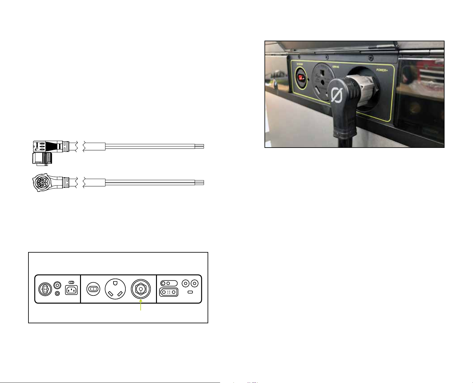
The Flying Leads to Power+ Cable plugs into the back of the Yeti PRO at a 90-degree
angle for more compact cabling.
CONNECTING V POWER TO THE YETI PRO
TOWABLES TRAILERS DRIVABLES RVVAN
The Flying Leads to Power+ Cable (SKU 98760). Green is Ground. White is Neutral.
Black is Live. This cable would generally be connected to the RV Shore Power Inlet.
Flying Leads to Solar HPP+ Input Cable
When connected to the Yeti PRO 4000, the Flying Leads to Solar HPP+ Input
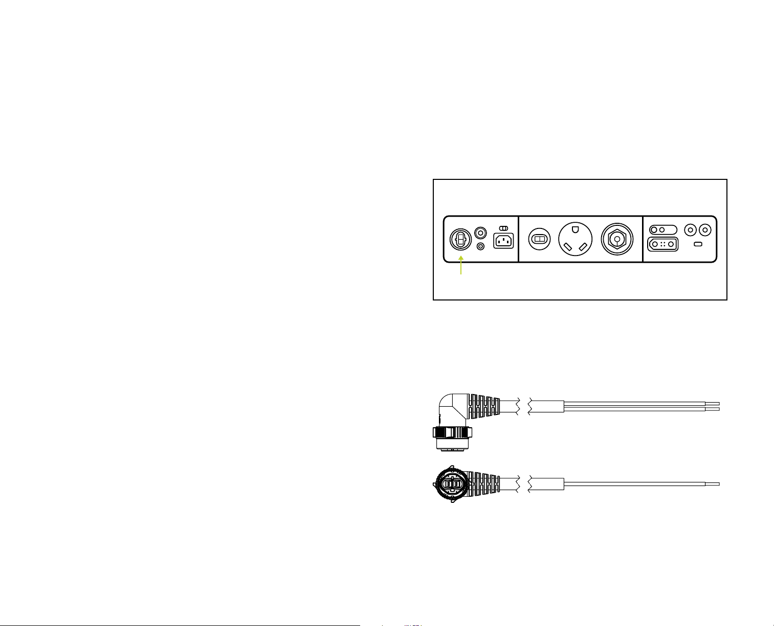
Cable (SKU 98730) will provide DC power IN to the Yeti PRO 4000. The Flying
Leads to Solar HPP+ Input Cable plugs into the HPP plug on the back of the
power station. This is to be used with the 3x HPP+ Solar Parallel Combiner Cable
(SKU 70030, sold separately) and solar panels to provide 12 V power supply to
the Yeti PRO 4000. Refer to the Yeti PRO 4000 User Guide for more information
BACK INTERFACE
on solar installation and configuration.
REQUIRED TOOLS:
• Multimeter
• Wrench Set (Metric/Standard)
Power+
• Phillips-Head Screwdriver
• Flat Head Screwdriver
The Power Plus Port on the back of the Yeti PRO 4000 where you will plug in the Flying
Leads to Power+ Cable.
• Hex Key Wrench Set
• Wire Strippers
• Zip Ties
• Dialectric Grease (to lubricate O-Rings on the Twist Lock)
6 7
Page 9
REQUIRED HARDWARE:
• Yeti PRO 4000
• Flying Leads to Solar HPP+ Input Cable (SKU 98730)
INSTALLATION:
1. Refer to the steps listed in the “Disconnecting OEM RV/Trailer Power
System” section (Page 4).
NOTE: The HPP+ Flying Leads Cable is color coded. The HPP+ has a Red
Wire for Positive and Black wire for Negative.
6. Do not reconnect the RV/Trailer batteries. The Yeti PRO 4000 replaces the
OEM trailer power system.
2. Once batteries are disconnected, locate and isolate the fuse box (12 V).
BACK INTERFACE
NOTE: This could be a house circuit with AC/DC fuse or breaker panel.
3. Locate the DC circuit.
• The 12 V circuit can be found at the battery selection switch/battery
master switch or DC fuse panel. This might be shared with the AC breaker
box.
4. If installing on battery selection switch/battery master switch, disconnect
RV/Trailer batteries.
High Voltage
DC Input
You can plug your solar directly into this port. This is also the port where you will plug
in the Escape Remote Display HPP+ Power and Data Adapter (Signal Splitter) to
connect the Escape Remote Display.
• Disconnect the Positive (+) cable from the battery selection switch/battery
master switch.
• Disconnect the Negative (-) cable from the battery selection switch/
battery master switch.
• Install the Flying Leads to Solar HPP+ Input Cable to desired battery
selection switch/battery master switch selection.
5. If installing wiring to open fuse terminal, connect the Flying Leads to Solar
HPP+ Input Cable to the fuse panel.
NOTE: If panel does not have spares, 12 V wiring terminals can be found
by tracing Positive (+) and Negative (-) terminals to fuse panel posts.
Disconnect the Positive (+) cable from battery selection switch/battery
master switch.
• Disconnect the Positive (+) cable from battery selection switch/battery
master switch.
HPP+ to Flying Leads cable for connecting Solar (SKU 98730)
• Disconnect the Negative (-) cable from battery selection switch/battery
master switch.
• Install Flying Leads to Solar HPP+ Input Cable to desired fuse panel
points.
8 9
Page 10
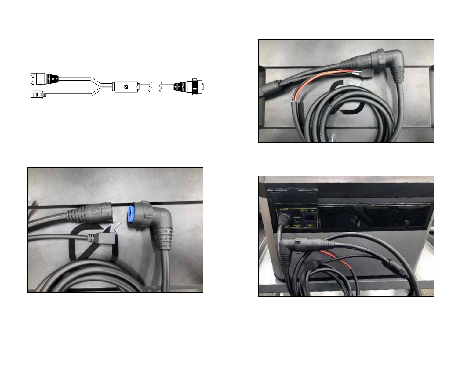
Escape Remote Display HPP+ Power and Data Adapter Cable (Signal Splitter)
(SKU 70035)
Example of HPP+ Data cable connection point.
From Left to Right: Receptacle HPP+ Input, RJ45 Jack for screen connection, HPP+
Data plug that plugs into the receptacle.
10 11
Escape Remote Display HPP+ Power and Data Adapter plugged into Yeti, and HPP+ to
Flying Leads Cable plugged into the Power and Data Adapter.
Page 11

CONNECTING SOLAR TO THE YETI PRO
INSTALLATION:
1. Locate a clear and open space on the roof of the RV/Trailer.
Optional Solar Panel Installation
You can recharge your Yeti PRO 4000 with connected roof-mounted Goal Zero
solar panels, portable Goal Zero solar panels, or third-party solar panels. You can
also combine mounted solar and portable solar panels for up to 3000 W of power
IN.
Connecting to Roof-Mounted Solar: Goal Zero and Third-Party Solar
Panels
REQUIRED TOOLS:
• Multimeter
• Wrench Set (10mm Socket)
• Hex Key Wrench Set (5 mm)
• Power Drill (Cordless/Corded)
• M4/4 mm Drill Bit
• Wire Strippers
• Terminal Crimpers
• Zip Ties
• Dialectric Grease (to lubricate O-Rings on MC4 Solar Connectors)
• Marking Tool (Paint Pen, Marker, Pencil)
• Silicone Sealer
REQUIRED HARDWARE:
• Goal Zero Solar Panels (Sold separately. NOTE: If using third-party solar
panels, connection points may vary)
• Flying Leads to Solar HPP+ Input Cable (SKU 98730 – included)
NOTE: If using third-party solar panels, extra MC4 Solar Connectors, a
waterproof/MC4 Passthrough, and extra cables are required
• Solar Panel Mounting Z-Brackets (SKU 96200 - included)
• M4 X 100 mm Bolts (Not Included)
• M4 Hex Nylone Lock Nut (Not Included)
• M4 Washers (Not Included)
2. Measure the space to ensure solar panels and Mounting Z-Brackets will fit.
3. Attach Solar Panel Mounting Z-Brackets to the solar panels.
4. Use the Solar Panel Mounting Z-Bracket footprints to mark mounting holes.
5. Use the 4 mm drill bit to drill marked mounting holes.
6. Apply a bead of silicone sealer around the bottom edge of the Mounting
Z-Bracket and to the drill hole for waterproofing.
7. Place solar panel on mounting surface and line holes up, using M4 fasteners
to securely attach.
8. Tighten fasteners.
NOTE: Mount all panels before mounting the MC4 passthrough.
9. Smooth out silicone sealer following the base edge of the Mounting
Z-Bracket, cleaning any excess from the face of the Mounting Z-Bracket.
10. Route Solar Cabling to the interior of the RV using industry standard
waterproofing techniques. This should be a waterproof seal.
11. Attach Solar Cabling to the HPP+ Flying Leads Cable in the interior of the
vehicle.
• After the Solar has been routed to the HPP+ Flying Leads Cable, this cable
will plug into the HPP+ Solar input port of the Yeti PRO or the Goal Zero 3
to 1 Parallel Combiner, dependent on the installation.
12 13
Page 12

CONNECTING TO COMBINED ROOFMOUNTED SOLAR
AND GROUNDDEPLOYABLE SOLAR PANELS VIA
BULKHEAD PASSTHROUGH
REQUIRED TOOLS:
• Multimeter
• Wrench Set (10 mm Socket)
• Hex Key Wrench Set (5 mm)
• Power Drill (Cordless/Corded)
• 1-inch Hole Saw for Bulkhead
• 4 mm Drill Bit
• Wire Strippers
• Terminal Crimpers
• Zip Ties
• Dielectric Grease (to lubricate O-Rings on MC4 Solar Connectors)
• Marking Tool (Paint Pen, Marker, Pencil)
• Silicone Sealer
REQUIRED HARDWARE:
• Goal Zero Solar Panels (NOTE: If using third-party solar panels, connection
points may vary)
• Flying Leads to Solar HPP+ Input Cable (SKU 98730)
• Solar Panel Mounting Z-Brackets (SKU 96200)
• M4 Phillips head
• Self-tapping screws
The Goal Zero bulkhead passthrough is a wall-mounted HPP+ port that is
installed to allow for ground-deployable solar panels. Refer to the Cable chart at
the beginning of this guide for more information.
For more information about solar installation and configuration, refer to the Yeti
4000 PRO User Guide on our website.
INSTALLATION OF THE GOAL ZERO BULKHEAD PASSTHROUGH:
1. Choose a location 1-2 feet from the bottom of the RV/Trailer “body.” The
installation location can vary depending on trailer or vehicle design.
2. Use a marking tool and stencil the bulkhead unit, marking the 4 mounting
holes.
3. Use a 4 mm drill bit to drill mounting holes through the trailer wall.
4.
Mark a 1-inch hole using the provided tool. Use a 1-inch hole saw, drill
through the bulkhead/side of the trailer.
5. Use supplied hardware to mount the bulkhead to the side of the trailer.
6. Connect the Escape Remote Display HPP+ Power and Data Adapter (SKU
70035) to the back of the Yeti PRO 4000 if using only ground-deployed
solar. If using both ground and roof-mounted solar, continue on to install the
3x HPP+ Solar Parallel Combiner Cable.
INSTALLATION OF THE X HPP SOLAR PARALLEL COMBINER CABLE:
1. Locate the Escape Remote Display HPP+ Power and Data Adapter. See the
Escape Remote Display installation section for more details.
2. Install the 3x HPP+ Solar Parallel Combiner Cable after the Escape Remote
Display HPP+ Power and Data Adapter.
3. Plug the ground and roof-mounted solar panels into the 3x HPP+ Solar
Parallel Combiner Cable, then plug into the Yeti PRO 4000 to recharge.
To combine mounted rooftop solar panels and ground-deployable solar panels
via the bulkhead passthrough, you will need to obtain the 3x HPP+ Solar Parallel
Combiner Cable (SKU 70030). This cable allows for both input sources to be
combined to recharge your Yeti PRO 4000. In van or other vehicle applications,
an additional alternator input will also be plugged into the 3x HPP+ Solar Parallel
Combiner Cable.
14 15
Page 13
CONNECTING ALTERNATOR OR TRAILER PIN TO THE YETI PRO
TOWABLES TRAILERS DRIVABLES RVVAN
Flying Leads to 8 mm DC Input Cable Installation:
The Flying Leads to 8 mm DC Input Cable (SKU 98775) provides DC power to
the Yeti PRO 4000 via the 7-pin trailer plug for Towable vehicles, or from the
alternator or battery in Drivable vehicles.
NOTE: The amperage from the 7-pin is manufacturer-dependent on the fusing
and alternator type and not the Goal Zero Yeti PRO 4000 system.
REQUIRED TOOLS:
• Multimeter
• Wrench Set (Metric/Standard)
• Wire Stripper
• Terminal Crimper
REQUIRED HARDWARE:
• Flying Leads to 8 mm DC Input Cable (SKU 98775)
• Wring Terminal Ends
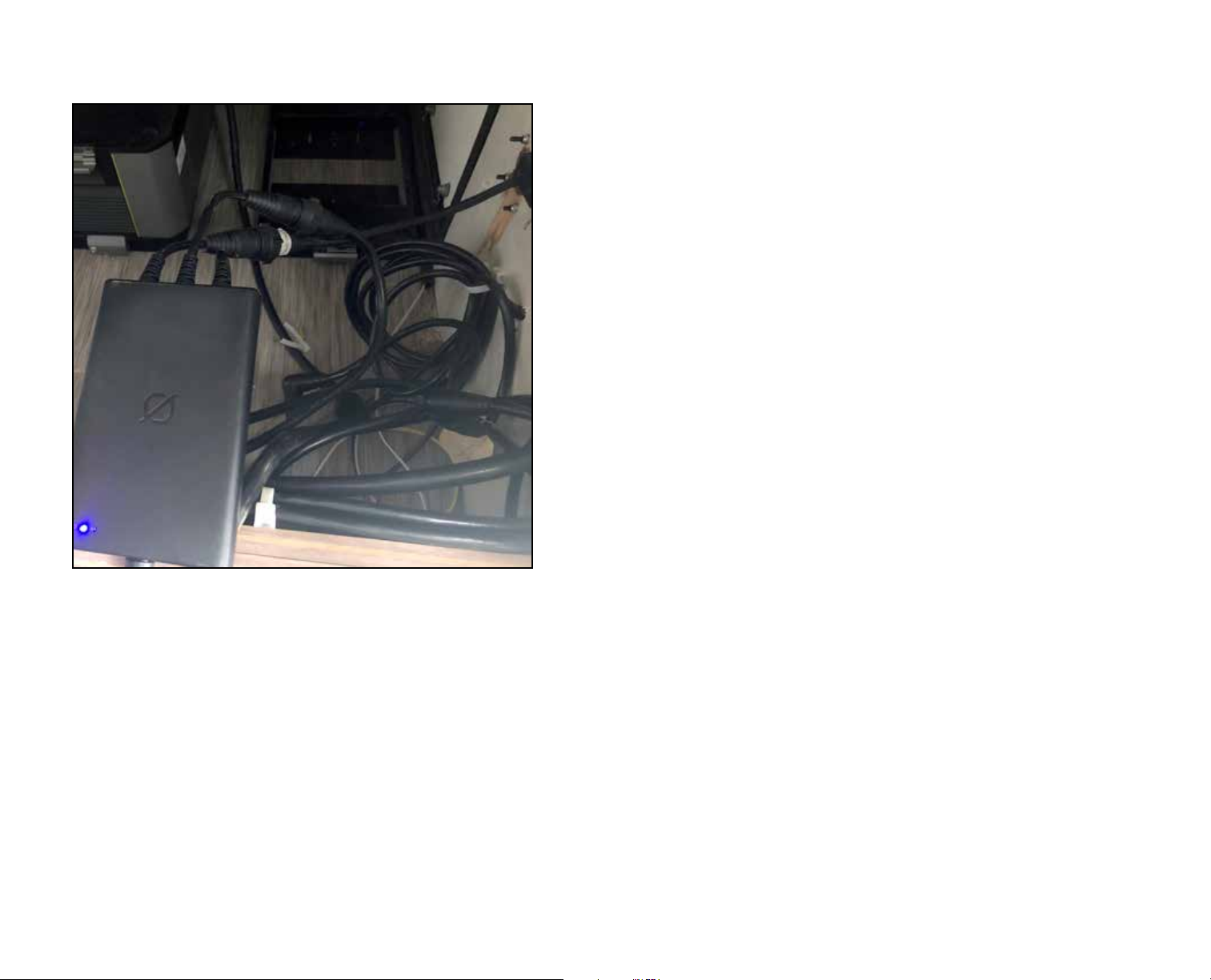
An example of how to connect solar into the 3:1 Parallel Combiner
INSTALLATION:
1. Locate the 12 V wire from the 7-pin trailer breakaway box. This should be a
black wire.
2. Connect the red wire from the Flying Leads to 8 mm DC Input Cable.
3. Locate the negative wire from the trailer 7-pin breakaway box. This should be
a white wire.
4. Connect the black wire from the Flying Leads to 8 mm DC Input Cable.
NOTE: If you are installing the system in a Drivable vehicle, connect the red
wire to the positive side of battery (12 V from the alternator fuse panel) and
ground the black wire to the battery, fuse panel, or to vehicle chassis.
16 17
Page 14
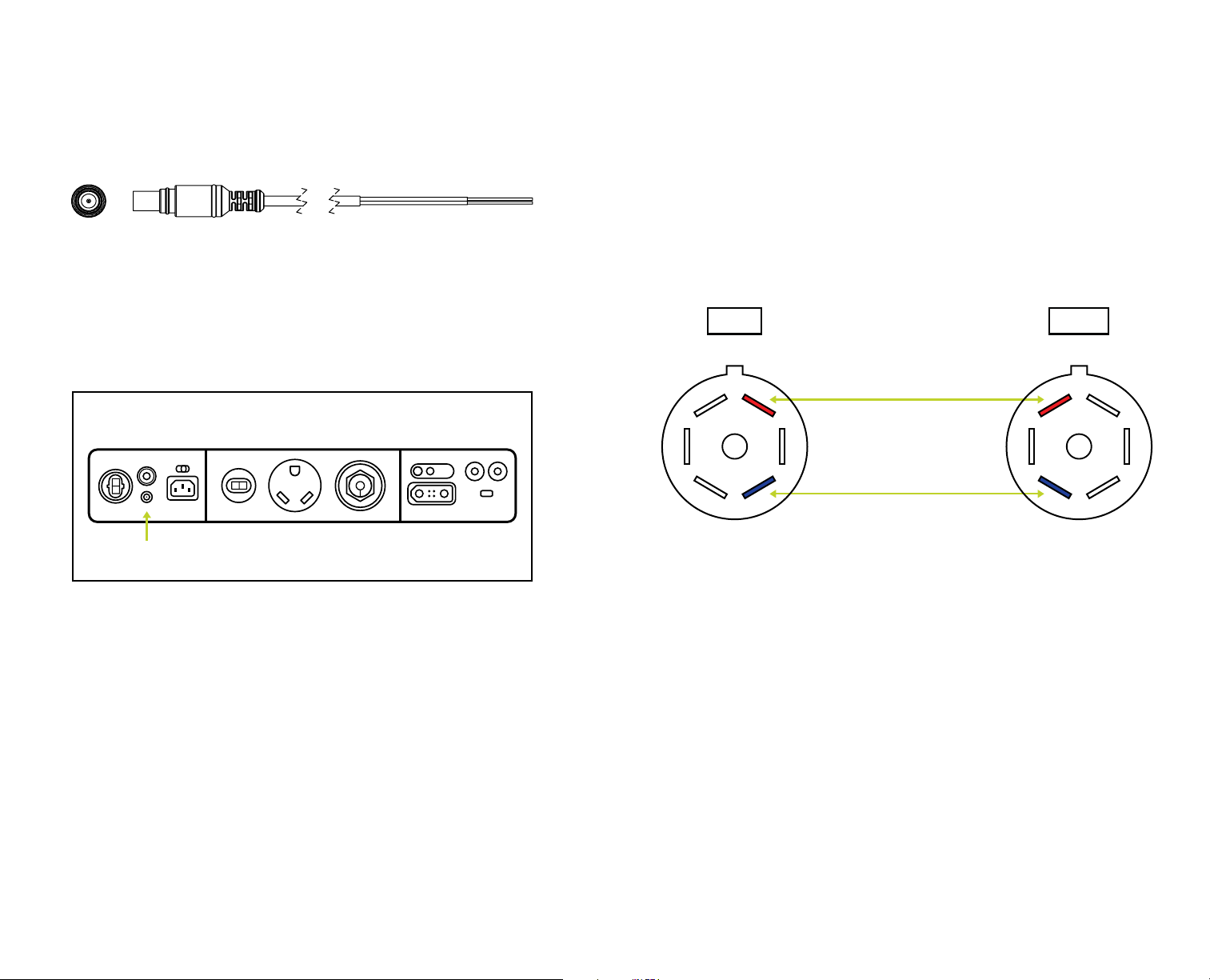
Flying Leads to 8 mm DC Input Cable. This can be used to wire in extra solar or
connect to an alternator for 10 A charging (SKU 98775).
WAY RV STYLE TRAILER PLUG WIRING
POLLOCK OR BARGMAN PLUG
TRUCK TRAILER
Aux 12 V+ Charging
Low Voltage
DC Input
The 8mm port on the Yeti PRO 4000
BACK INTERFACE
3 4
5 7 6
1 2
Trailer Brakes
4 3
6 7 5
2 1
NOTE: The amperage from the 7-pin is manufacturer-dependent on the fusing
and alternator type and not the Goal Zero Yeti PRO 4000 system.
18 19
Page 15
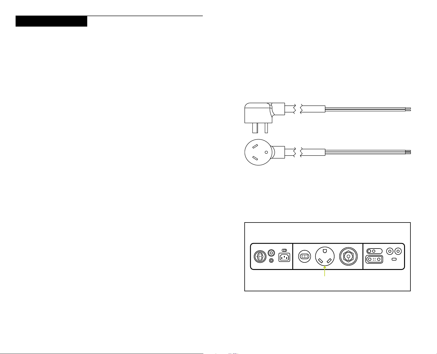
Setting Up Power Out
YETI TO AC BREAKER PANEL VIA TT CABLE
TOWABLES TRAILERS DRIVABLES RVVAN
TT-30 to Flying Leads Cable
When connected to the Yeti PRO 4000, the TT-30 to Flying Leads Output Cable
(SKU 98765) will provide AC power OUT to the RV/Trailer. Refer to the Cable
chart at the beginning of this guide for more information. The TT-30 to Flying
Leads Output Cable plugs into the RV (TT-30) plug on the back of the Yeti PRO
4000. The AC button must be pressed “ON” on the front of the Yeti PRO 4000
for the Escape Display screen to power RV/Trailer devices.
REQUIRED TOOLS:
• Multimeter
• Wrench Set (Metric/Standard)
• Phillips-Head Screwdriver
• Flat Head Screwdriver
• Hex Key Wrench Set
• Wire Strippers
• Terminal Crimpers
• Zip Ties
3. The shore power inlet generally represents the input to the vehicle or trailer
breaker panel. The recommended connection point for the Yeti inverter is
at the input of the trailer or vehicle 120 V breaker panel. Please be sure to
follow RVIA and NEC requirements when installing.
NOTE: Flying Leads Cables are color coded. Black is hot, white is neutral,
and green is ground. Match the wiring accordingly.
TT-30 to Flying Leads Output Cable (SKU 98765). Designed for 30 A output from the
Yeti PRO 4000. This has a TT-30 connection to plug directly into the Yeti PRO 4000
and flying leads to be directly wired into a vehicle’s 120 V system.
REQUIRED HARDWARE:
• Yeti PRO 4000
• TT-30 to Flying Leads Output Cable (SKU 98765)
BACK INTERFACE
INSTALLATION:
1. Be sure to understand the 120 V electrical system of your particular trailer
or vehicle. If you have questions regarding wire routing within your vehicle,
consult the trailer manufacturer or a certified technician.
2. Be sure the AC bus in your trailer or vehicle is non-energized prior to
installation. Locate the AC Breaker panel. This usually can be traced from the
You can plug your solar directly into this port. This is also the port where you will plug
in the Escape Remote Display HPP+ Power and Data Adapter (Signal Splitter) to
connect the Escape Remote Display.
30A RV
AC Output
shore power inlet.
20 21
Page 16
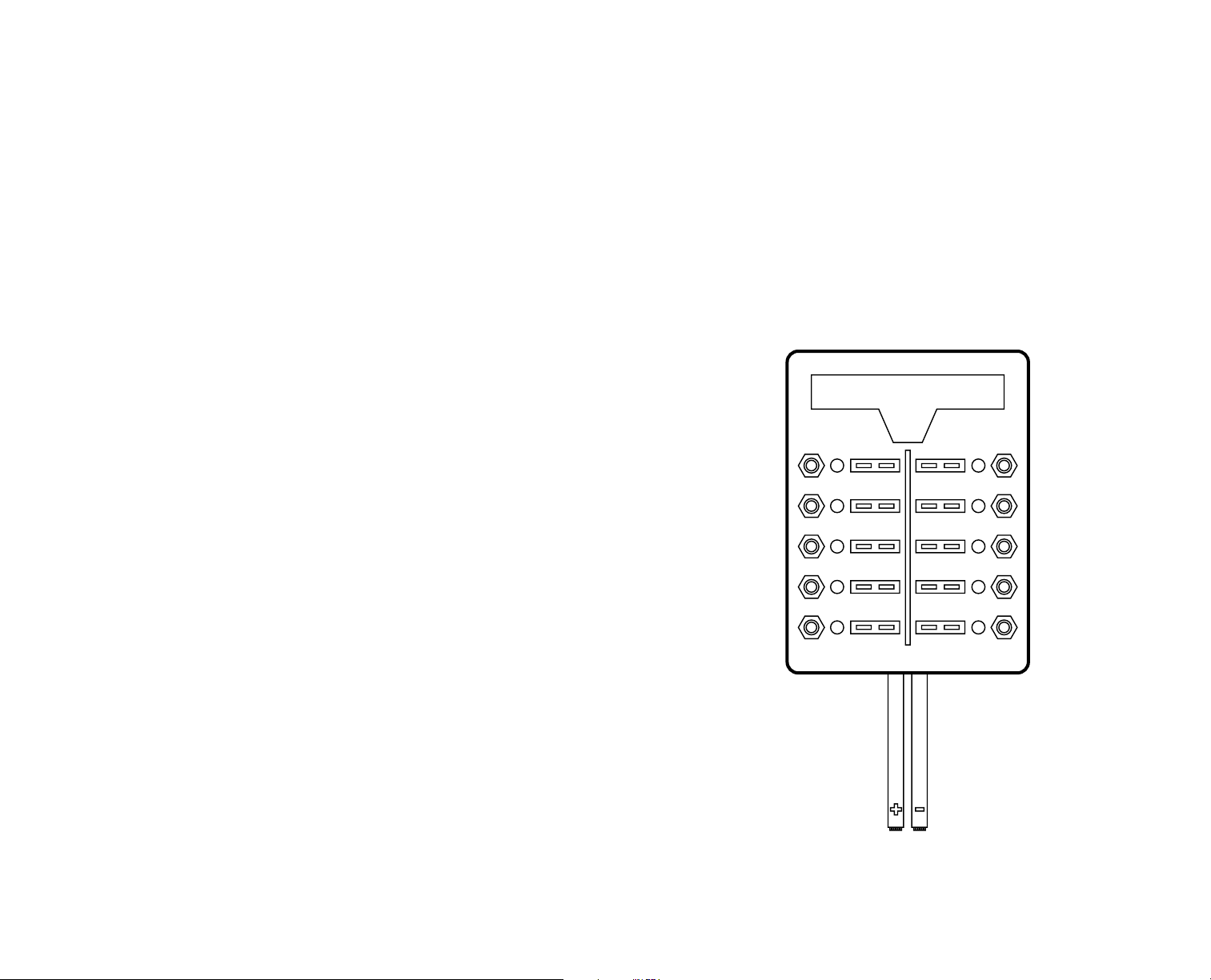
YETI TO DC BREAKER PANEL VIA V POWER
TOWABLES TRAILERS DRIVABLES RVVAN
12V Locking HPP to Flying Leads Output Cable
When connected to the Yeti PRO 4000, the 12 V Locking HPP to Flying Leads
Output Cable (SKU 98735) will provide a DC power supply OUT to the 12 V
systems on the RV/Trailer. The 12 V Locking HPP to Flying Leads Output Cable
plugs into the 12 V DC Out port plug on the back of the Yeti PRO 4000.
REQUIRED TOOLS:
• Multimeter
• Wrench Set (Metric/Standard)
• Phillips-Head Screwdriver
• Flat Head Screwdriver
• Hex Key Wrench Set
• Wire Strippers
• Terminal Crimpers
• Zip Ties
• Dialectric Grease (to lubricate O-Rings on Twist Lock)
4. If installing wiring to open fuse terminal, connect the Flying Leads of the
HPP+ 12 V Cable to the fuse panel. NOTE: If panel does not have spares,
(12 V) wiring terminals can be found by tracing Positive (+) and Negative (-)
terminals to fuse panel posts.
• Disconnect Positive (+) cable from battery selection switch/battery master
switch (if applicable).
• Disconnect Negative (-) cable from battery selection switch/battery master
switch (if applicable).
REQUIRED HARDWARE:
• Yeti PRO 4000
• 12 V Locking HPP to Flying Leads Output Cable (SKU 98735)
• HPP+D to Flying Leads Cable (Sold Separately)
INSTALLATION:
1. Refer to the steps listed in the “Disconnecting OEM RV/Trailer Power
System” section (Page 4).
2. Once the RV/Trailer batteries are disconnected, locate and isolate the AC
Inverter.
NOTE: The AC Inverter may be a standalone inverter or an integrated
inverter.
Attaching the 12 V output from the Yeti 4000 PRO to the RV’s 12 V electrical system.
It can be connected directly to the terminal blocks inside the RV’s electrical fuse panel.
3. Locate (12 V) DC Power Bus.
22 23
Page 17
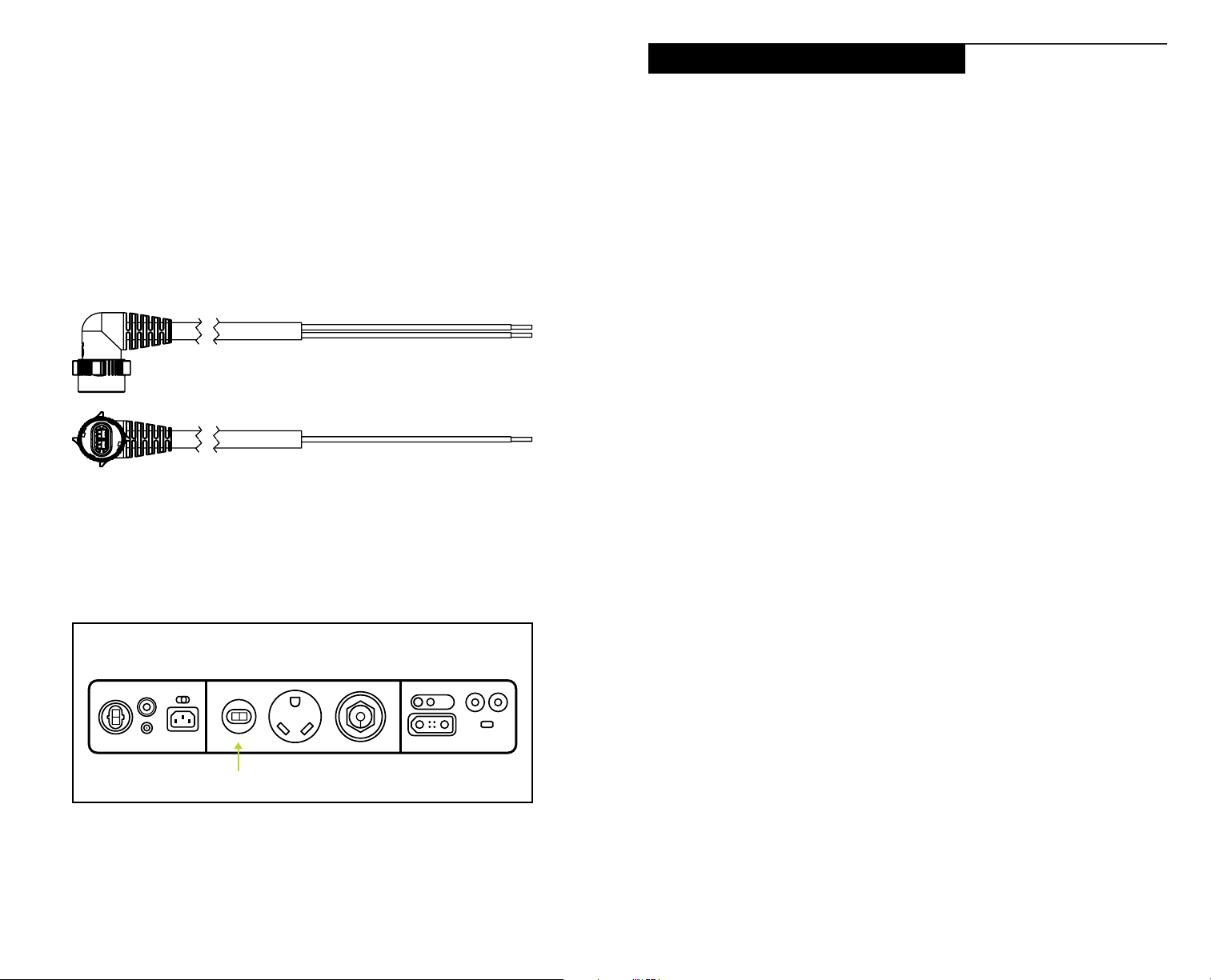
Escape Remote Display Installation
5. Install 12 V Locking HPP to Flying Leads Output Cable to desired fuse panel
points.
NOTE: The HPP+ 12 V Flying Leads Cable is color coded. Red is Positive,
Black is Negative.
6. Do not reconnect the RV/Trailer batteries. The Yeti PRO 4000 replaces the
OEM trailer power system.
12 V Locking HPP to Flying Leads Output Cable (SKU 98735). Designed to connect
power from the Yeti PRO 4000 to the 12 V appliances inside your RV.
BACK INTERFACE
ELECTRICAL REQUIREMENTS:
• Input Voltage: 9 V to 60 V (Designed to work with Yeti PRO 4000 that provides
24 V)
• Operational Current: 10 mA
• HPP+ 15 ft. Cable, optional (SKU 98700)
REQUIRED TOOLS:
• ¼ inch Drill Bit
• Power Drill (Cordless/Corded)
• Marking Tool (Paint marker/Pencil)
REQUIRED HARDWARE INCLUDED:
• Knurled Nuts
• Threaded Posts
INSTALLATION:
1. Connect the Escape Remote Display HPP+ Power and Data Adapter to the
High Voltage DC input on the back of the Yeti via the signal splitter on the
Yeti PRO 4000 with the Escape Remote Display Data Cable (SKU 98082)
or 3x HPP+ Solar Parallel Combiner Cable (May not be used in system. See
solar installation section for details) connection on the Escape Remote
Display HPP+ Power and Data Adapter.
NOTE: The Escape Remote Display HPP+ Power and Data Adapter must be
plugged into the Yeti before the 3x HPP+ Solar Parallel Combiner Cable. The
reverse is not recommended.
2. Plug in the Escape Remote Display Data Cable to the Escape Remote
Display HPP+ Power and Data Adapter at the RJ45 Port (RJ45 port can be
found on the Escape Remote Display HPP+ Power and Data Adapter). The
Escape Remote Display Data Cable is a CAT-5 1 to 1 patch cable.
12V HPP
The Port on the Yeti PRO 4000 where you plug in the 12 V Locking HPP to Flying
Leads Output Cable.
24 25
Page 18
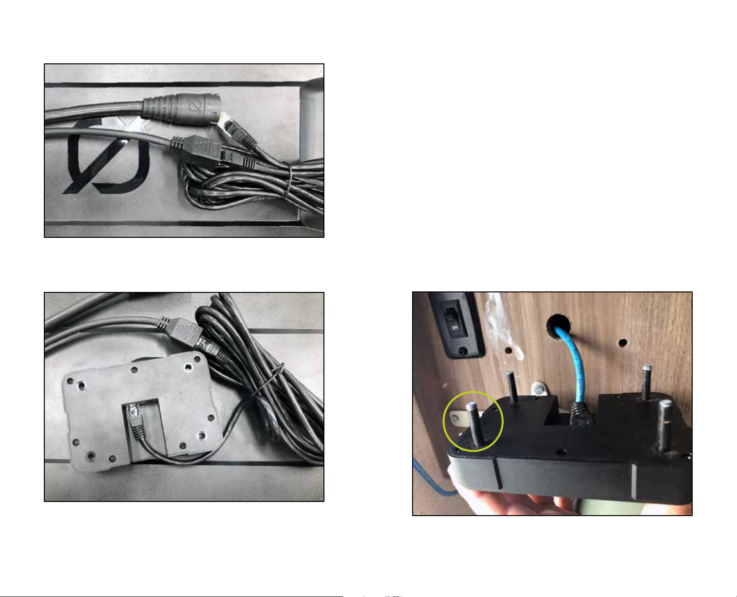
The Escape Remote Display Data Cable (SKU 98082) plugs into the Escape Remote
Display HPP+ Power and Data Adapter (SKU 70035).
3. Route the cable to the desired mounting position of the Escape Remote
Display Unit (SKU 70045). This screen should be visible and readable at eye
level. It should not be exposed to liquids and is intended to be mounted inside
the cabin of any RV or trailer.
4. Mount the Escape Remote Display Unit.
a. Before drilling holes, measure the space to ensure the display will fit.
b. Mark mounting holes. Line up your display with the wall to use it as a
template.
c. Drill all holes.
d. Attach the connector to the back side of the RVES Screen.
e. Ensure threaded posts of the screws are mounted to the back of the
Escape Remote Display Unit.
NOTE: Screen can also be mounted with 3M double sided tape (not
included) if location does not permit drilling.
Escape Remote Display Data Cable (SKU 98082) plugs into the RJ45 port on the
Escape Remote Display (SKU 70045).
NOTE: Either RJ45 port can be used.
26 27
Attaching Threaded Posts to the Escape Remote Display.
Page 19
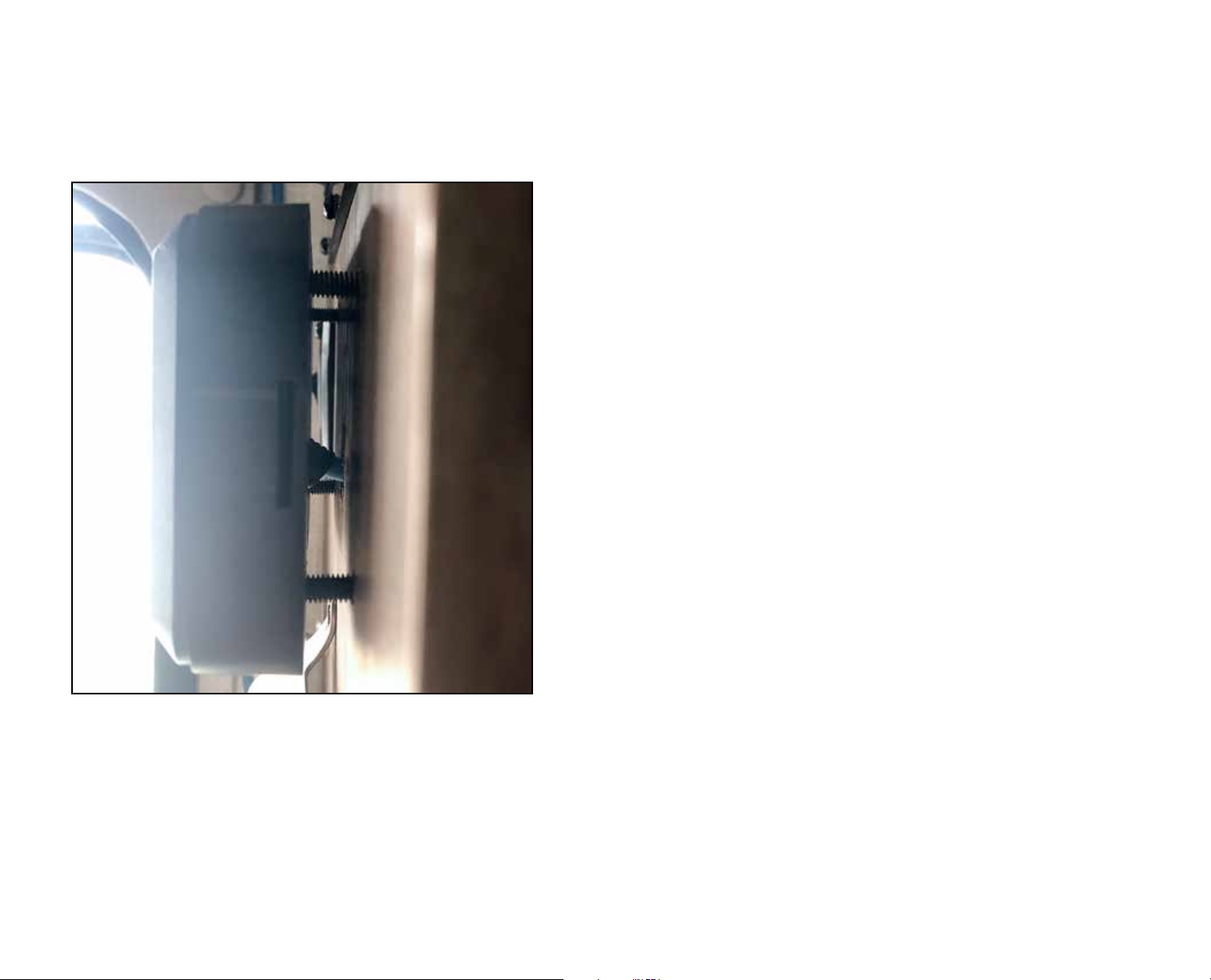
f. Place the threaded posts through the drilled holes and hand tighten the
provided knurled nuts. HAND TIGHTEN ONLY to protect the threads on
the RVES Screen.
Escape Remote Display (SKU 70045) mounted flush to the wall of the vehicle.
NOTE: Cabling may come out from the bottom of the display if hidden cabling is
not possible.
Once the screen is installed, the Yeti PRO 4000 will automatically recognize
the screen’s presence and the “EXP” icon will appear on the Yeti. If this does not
occur, please contact our support team at 1-888-794-6250.
NOTE: For additional details on using and reading the screen with your Yeti
PRO 4000, please see the user guide that is included with the Escape Remote
Display.
28 29
Page 20

30 31
Page 21

GOAL ZERO HEADQUARTERS
Draper, UT 84020
1-888-794-6250
Designed in the U.S.A.
Made in China
Goal Zero Yeti is a trademark of Goal Zero.
This equipment has been tested and found to comply with the limits for a Class
B digital device, pursuant to part 15 of the FCC Rules. These limits are designed
to provide reasonable protection against harmful interference in a residential
installation. This equipment generates, uses and can radiate radio frequency
energy and, if not installed and used in accordance with the instructions, may cause
harmful interference to radio communications. However, there is no guarantee that
interference will not occur in a particular installation. If this equipment does cause
harmful interference to radio or television reception, which can be determined
by turning the equipment off and on, the user is encouraged to try to correct the
interference by one or more of the following measures:
—Reorient or relocate the receiving antenna.
—Increase the separation between the equipment and receiver.
—Connect the equipment into an outlet on a circuit different from that to which the
receiver is connected.
—Consult the dealer or an experienced radio/TV technician for help.
This device complies with part 15 of the FCC Rules. Operation is subject to the
following two conditions: (1) This device may not cause harmful interference, and (2)
this device must accept any interference received, including interference that may
cause undesired operation.
32
REV A
 Loading...