

EXTREME SERIES
Adjustable Height Goal Systems
Made In The USA
Installation
& Owner’s
Instructions
• X672
• X660
• X560
• X554
• X454
• X448

Extreme Series Goal System Instructions
This manual explains the proper
installation, operation and maintenance of
your Goalsetter Goal. Study and
understand these instructions thoroughly
before installing, operating or maintaining
the goal. Failure to do so could result in
serious injury or death and/or equipment
damage. Consult your Goalsetter dealer or
Goalsetter Systems, Inc. if you do not
understand the instructions in this manual
or need additional information.
Goalsetter Systems, Inc. recommends that
you retain this manual for future reference
of operation, maintenance and parts
information.
The instructions, illustrations and
specifications in this manual are based on
the latest information available at the time
of publications. Your goal may have
product improvements and options not yet
contained in this manual.
Goalsetter Systems, Inc. reserves the right
to make changes at any time without
notice or obligation.
Additional copies of these instructions are
available from Goalsetter Systems, Inc.
2 www.goalsettersystems.com 800.362.GOAL (4625)
GOALSETTER®, GOALSETTER SYSTEMS®AND GOALSETTER®logo
are all registered trademarks of Goalsetter Systems, Inc. in the U.S.
and/or other countries.
GS
™
and BEST IN BASKETBALL™are trademarks of Goalsetter
Systems, Inc.
This product is covered by various U.S. and Canadian patents,
including U.S. Patent #5,211,393.
Patent infringement will be pr
osecuted.
No part of this manual may be reproduced in any form or by any
means electronic or mechanical, including photocopying, recording,
or by any information storage and retrieval systems without the
express written consent of Goalsetter Systems, Inc.
Copyright 2006.
Revised 6/9/2008.
All Rights Reserved.
Goalsetter Systems, Inc.
Questions? Comments? Contact Us:
Phone: 800.362.4625 • Fax: 641.594.3343
Email: info@goalsettersystems.com
www.goalsettersystems.com

Extreme Series Goal System Instructions
TABLE OF CONTENTS
Contact Information . . . . . . . . . . . . . . . . . . . . . . . . . . . . . . . . . . . . . . . .2
Thank You . . . . . . . . . . . . . . . . . . . . . . . . . . . . . . . . . . . . . . . . . . . . . . . .4
Lay Out Playing Court . . . . . . . . . . . . . . . . . . . . . . . . . . . . . . . . . . . . . .4
Court Markings (reference only) . . . . . . . . . . . . . . . . . . . . . . . . . . . . . .4
Safety Instructions . . . . . . . . . . . . . . . . . . . . . . . . . . . . . . . . . . . . . . . . .5
Ground Anchor Installation . . . . . . . . . . . . . . . . . . . . . . . . . . . . . . . . . .6
Call "One-Call" . . . . . . . . . . . . . . . . . . . . . . . . . . . . . . . . . . . . . . . . . . .6
Required Tools and Materials . . . . . . . . . . . . . . . . . . . . . . . . . . . . . . . .6
Ground Anchor Placement . . . . . . . . . . . . . . . . . . . . . . . . . . . . . . . . . .7
Installation . . . . . . . . . . . . . . . . . . . . . . . . . . . . . . . . . . . . . . . . . . . . . . .8
Dig Hole . . . . . . . . . . . . . . . . . . . . . . . . . . . . . . . . . . . . . . . . . . . . . . . .8
Position Anchor and Fill With Concrete . . . . . . . . . . . . . . . . . . . . . . . .8
Goal Specifications . . . . . . . . . . . . . . . . . . . . . . . . . . . . . . . . . . . . .12-13
Goal Assembly . . . . . . . . . . . . . . . . . . . . . . . . . . . . . . . . . . . . . . . . . . . .9
Required Tools and Materials . . . . . . . . . . . . . . . . . . . . . . . . . . . . . . . .9
Hardware Identification . . . . . . . . . . . . . . . . . . . . . . . . . . . . . . . . . .9-11
Parts List . . . . . . . . . . . . . . . . . . . . . . . . . . . . . . . . . . . . . . . . . . . .14-15
Pole Assembly . . . . . . . . . . . . . . . . . . . . . . . . . . . . . . . . . . . . . . . .16-17
Backboard Attachment . . . . . . . . . . . . . . . . . . . . . . . . . . . . . . . . . . . .18
Goal Alignment . . . . . . . . . . . . . . . . . . . . . . . . . . . . . . . . . . . . . . . . . .19
Rim Attachment . . . . . . . . . . . . . . . . . . . . . . . . . . . . . . . . . . . . . . . . .20
Height Indicator Attachment . . . . . . . . . . . . . . . . . . . . . . . . . . . . . . . .21
Operation and Maintenance . . . . . . . . . . . . . . . . . . . . . . . . . . . . .21-22
Cleaning . . . . . . . . . . . . . . . . . . . . . . . . . . . . . . . . . . . . . . . . . . . . . . .21
Operation . . . . . . . . . . . . . . . . . . . . . . . . . . . . . . . . . . . . . . . . . . . . . .21
Lubrication . . . . . . . . . . . . . . . . . . . . . . . . . . . . . . . . . . . . . . . . . . . . .22
Maintenance
. . . . . . . . . . . . . . . . . . . . . . . . . . . . . . . . . . . . . . . . . . . .
22
W
arranties
. . . . . . . . . . . . . . . . . . . . . . . . . . . . . . . . . . . . . . . . . . . . . . .
23
800.362.GOAL (4625) www.goalsettersystems.com 3
Extreme Series Goal System Instructions
4 www.goalsettersystems.com 800.362.GOAL (4625)
Thank you and congratulations for purchasing a Goalsetter Goal – the finest
basketball goal system on the market today!
You will discover that Goalsetter is
unsurpassed in product innovation, quality and integrity in the basketball equipment
industry.We are continually focused on designing, engineering and producing products
that meet and exceed the expectations of today’s toughest playing environments and
demanding players. Please contact us if you have any concerns, questions or suggestions
regarding our products.
THANK YOU!
LAY OUT PLAYING COURT
Consider the following to determine where to install the basketball goal:
• Whether the goal is to be installed into a landscaped area next to the
playing surface or into a hard-surfaced area.
• Backboard size and its extension distance from the structure.
• If court markings ar
e to be used.
• Amount of playing surface desired beneath the goal.
• Other functions of playing surface (such as driveway, tennis court, etc.)
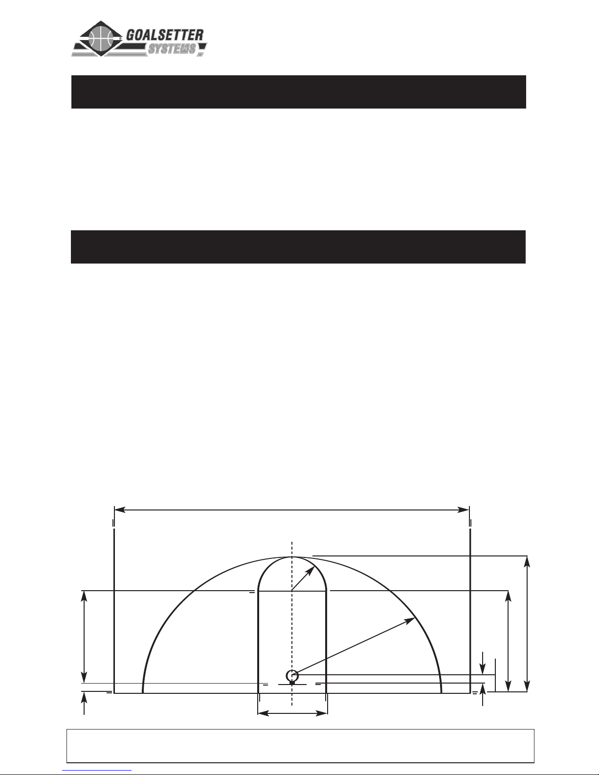
Court Markings (reference only)
6'-0"
19'-9"
50'-0" Optimum Inside Sidelines
15'-0"
19'-0"
25'-0"
63"
15"
12'-0"
4'-0"
Note: Lines are 2" wide.
Regulation Court Lengths:
High School: 84'
College: 94'
Professional: 94'
Extreme Series Goal System Instructions
800.362.GOAL (4625) www.goalsettersystems.com 5
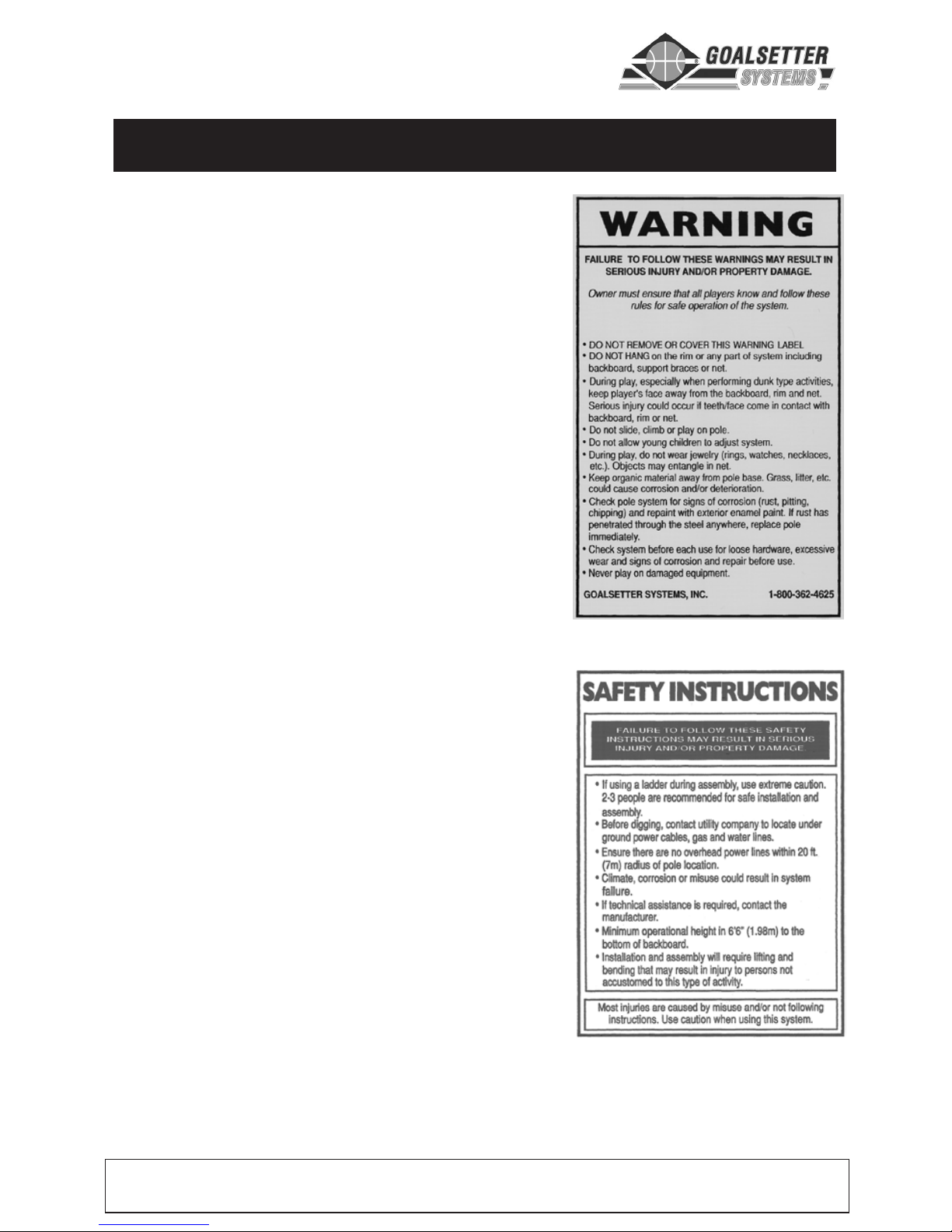
Failure to follow these safety instructions may
result in serious injury or death and/or property
damage.
•
Do not install or use this product unless the
instructions within this manual have been
carefully read and understood.
• Consult your Goalsetter dealer or Goalsetter
Systems, Inc. if you do not understand the
instructions in this manual or need additional
information.
• Before digging for the ground anchor, contact
your local One-Call system in your area.
• If using a ladder during assembly, use extreme
caution. Two or three people are recommended
for safe installation and assembly.
• Installation and assembly of this product will
require lifting and bending that may result in injury
to anyone not accustom to this type of activity.
• Ensure there are no overhead power lines within a
20 ft. (7 m.) radius of the goal location.
• Climate, corrosion or misuse could result in
system failure.
• With rim set at 7'-0" playing height, the minimum
operational height is 6'-4" (1.9 m) to the bottom of
the backboard.
• DO NOT HANG on the rim or any part of the goal
system. This includes the backboard, support
braces or net.
• During play, especially when performing dunking
activities, keep the player’s face away from the
backboard, rim and net. Serious injury could result
if teeth/face come in contact with the backboard,
rim or net. Do not wear jewelry or other loose
objects that could become entangled in the net.
• Twice yearly, check the goal system for loose
hardware, excessive wear and signs of corrosion. Repair the system before use.
• Never play on damaged equipment.
SAFETY INSTRUCTIONS
Extreme Series Goal System Instructions
6 www.goalsettersystems.com 800.362.GOAL (4625)
GROUND ANCHOR INSTALLATION
Contacting buried utilities may cause serious injury or death. Before you
start digging, always contact your local One-Call system to help prevent
personal injury, interruption of services, environmental accidents or job
delays.
Electric lines can shock or electrocute. Gas lines can rupture causing
explosion or fire. Laser light in fiber optic cable can cause blindness.
One-Call will notify participating utility companies of your proposed
digging project. I
f you do not know the number for the local One-Call
in your area, call the National One-Call at 1-888-258-0808 for this
information.
After being notified, utility companies will mark their
underground facilities by using the following international marking
codes:
Color Definition
Red Electric
Yellow Gas, Oil or Petroleum
Orange Communication, Telephone, TV
Blue Portable Water
Green/Brown Sewer
White Proposed Excavation
Pink Surveying
Spade
Shovel
Tape Measure
Level
Stir Rod
Auger or Post Hole Digger
10-14, 60 lb. Bags of Dry Concrete Mix
(or 1/4 - 1/3 yard of ready mix concrete
may be substituted for the concr
ete mix)
W
ater
Required Tools and Materials
Extreme Series Goal System Instructions
800.362.GOAL (4625) www.goalsettersystems.com 7
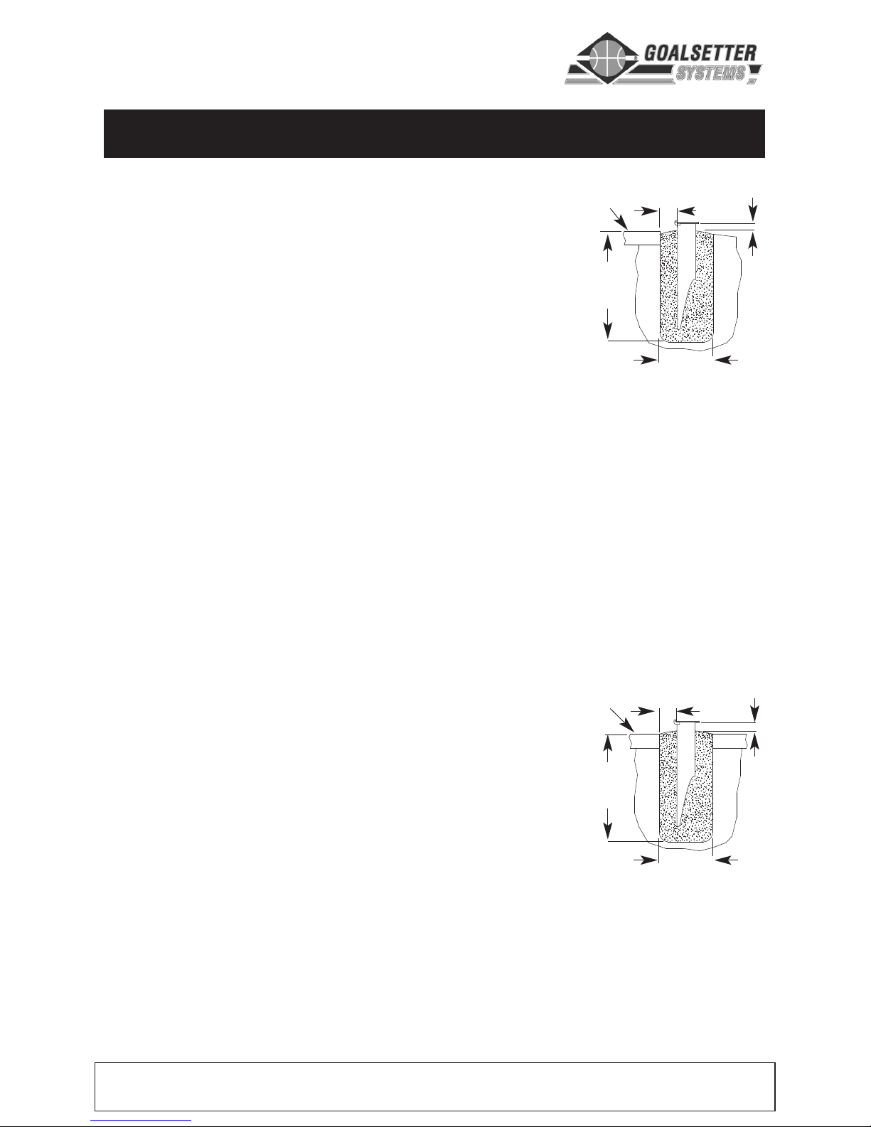
GROUND ANCHOR PLACEMENT
Use the following guidelines when installing
ground anchor into a
hard-surfaced area:
•Top of ground anchor to be 1"
(25 mm) above playing surface.
•Concrete fill should have top sloped away from
anchor in all directions to shed moisture away.
•Top of ground anchor must be level both
directions across its surface.
•Hinge side of anchor toward playing surface.
•Hinge parallel with playing surface.
•Distance from edge of hole made in playing surface to anchor to be
no less than 6" (152 mm).
•Distance from bottom of ground anchor plate to concrete fill to be
no less than 1" (25 mm).
IMPORTANT – When preparing for ground
anchor, allow at least 6" (152 mm) from all sides
of ground anchor to wall of hole to allow for
sufficient concrete fill around anchor.
Use the following guidelines when installing
ground anchor into a
landscaped area next to
the playing surface:
•Top of ground anchor to be flush with or
slightly above playing surface.
•Top of ground anchor must be level both directions across its surface.
•Concrete fill should have top sloped away from anchor in all
dir
ections to shed moistur
e away.
•Hinge side of anchor toward playing surface.
•Hinge parallel with playing surface.
•Distance from edge of playing surface to anchor to be no less than 6"
(152 mm).
•Distance from bottom of ground anchor plate to concrete fill to be no
less than 1" (25 mm).
48-50"
(1.2-1.3 m)
1" (25 mm) minimum
18" (0.5 m)
6
" (152 mm)
all sides
Playing Surface
48-50"
(1.2-1.3 m)
1" (25 mm)
18" (0.5 m)
6" (152 mm)
all sides
Playing Surface
Extreme Series Goal System Instructions
GROUND ANCHOR INSTALLATION
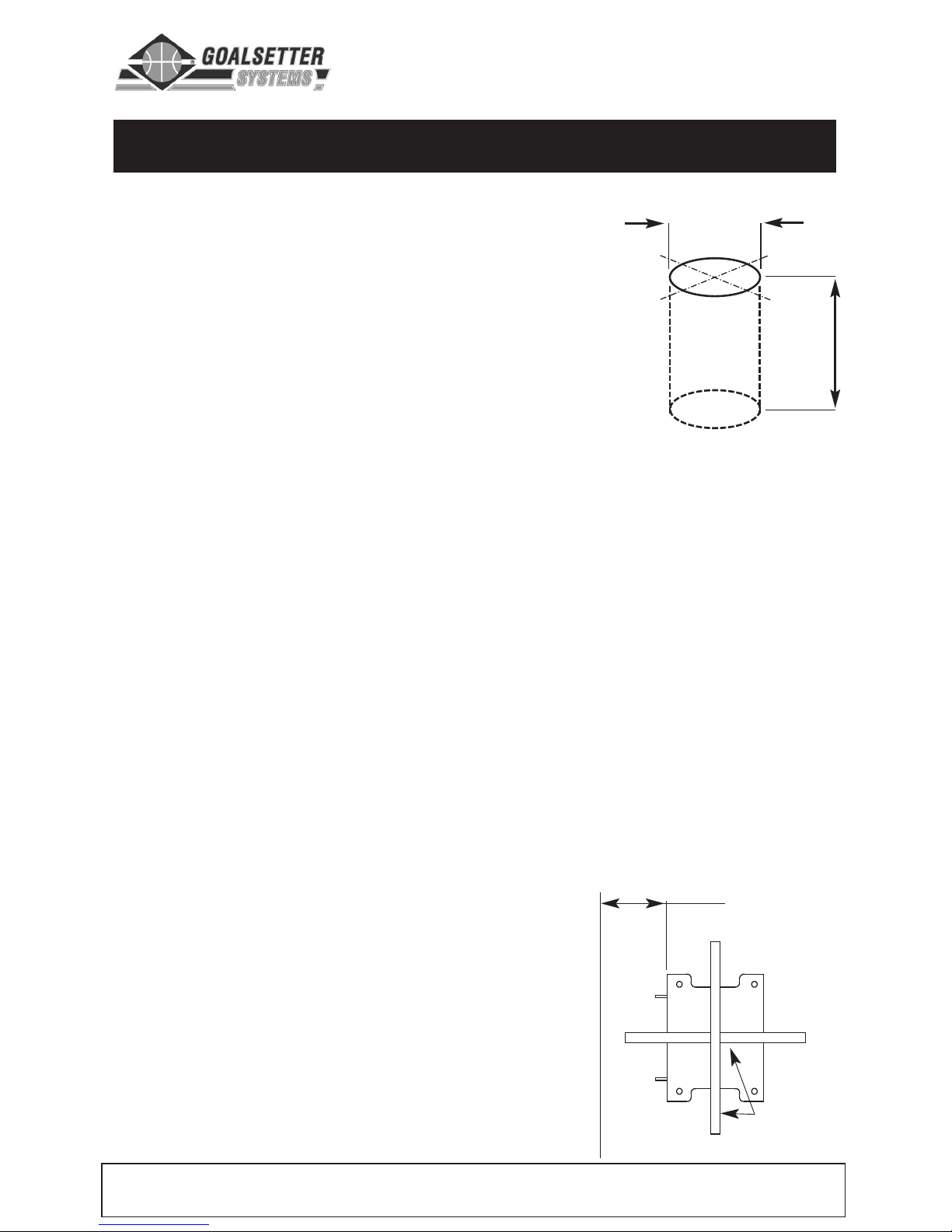
Dig Hole – When installing goal into a hard-
surfaced area, a minimum of a 18" x 18" (0.5 x
0.5 m) area of the hard surface will need to be
removed.
Step 1 – Once location of goal has been
determined, locate center of ground anchor hole.
Step 2 – Dig a hole approximately 18 " (0.5 m) in
diameter and 48-50" (1.2-1.3 m) deep. Use a
spade, shovel, auger or post hole digger.
Position Anchor and Fill Hole with Concrete Mix – For best
performance,
do not fully fill hole with concr
ete mix befor
e positioning
the anchor.
Instead, fill base of hole with concrete mix, lower the
ground anchor into the hole, position it and then finish filling with
concrete mix.
Step 1 – Locate and unpack ground anchor. Do not remove plastic
plugs or hinge bolt.
Step 2
– Place 2-3 bags of concr
ete mix into hole; add water and stir.
Follow concrete mix manufactur
er’s instructions for best results.
Step 3 – Position anchor in center of hole with hinge side toward and
parallel with playing surface.
IMPORTANT – As hole is filled with concrete mix, periodically place a
level on top of anchor plate and check that it is level front-to-back and
left-to-right. Also check that the top of anchor is at correct height.
Step 4 – Adjust anchor plate height,
depending upon installation, per
guidelines given in Ground Anchor
Placement.
Step 5 – Continue filling hole with
concrete mix until it is within 1"-1.5"
(25-38 mm) of anchor plate bottom, or
level with landscape – whichever
comes first.
6" (152 mm)
minimum AND
parallel
Check level both
directions
Playing Surface
48-50"
(1.2-1.3 m)
1
8" (0.5m)
Diameter
8 www.goalsettersystems.com 800.362.GOAL (4625)

Extreme Series Goal System Instructions
800.362.GOAL (4625) www.goalsettersystems.com 9
GOAL ASSEMBLY
IMPORTANT: Concrete must cure a minimum of 48 hours before
installing goal.
IMPORTANT: Safe assembly of the goal requires two to three people
in good physical condition and capable of lifting 80-100 lbs (36-45 kg)
each.
IMPORTANT: Locate and familiarize yourself with all parts of the goal
before beginning assembly.
Level
Rubber Mallet
12' Tape Measure
Phillips Scr
ewdriver
Ratchet
9/16" and 3/4" Sockets
9/16" and 3/4" Wrenches
Required Tools and Materials
HARDWARE IDENTIFICATION
Rim Bolt Assembly
(All Models)
14a
14b
14c
14d
Height Indicator Decal
(All
Models)

Extreme Series Goal System Instructions
10
www
.goalsettersystems.com
800.362.GOAL
(4625)
HARDWARE IDENTIFICATION
Anchor Hinge Bolt
(All Models)
2a
2b
Assembly Lock Plate
(All Models)
NOTE: Refer to page 12-15 for descriptions and quantities.
6a
6b
6b
6d
Jack Lower Pivot Bolt Assembly
6c
Black Touch-Up Paint
Ground Anchor Bolt Assembly
(All Models)
4a
4b

Extreme Series Goal System Instructions
800.362.GOAL
(4625)
www.goalsettersystems.com 11
HARDWARE IDENTIFICATION
Extension Arm Bolt Assembly
8" (X448 & X454)
10" (X554 & X560)
11" (X660 & X672)
8a
8b
8b
8d
Backboard Bolt Assembly
8" (X448 & X454)
2-1/2" (X554 & X560)
3-1/4" (X660 & X672)
11a
11b 11b 11c
8c
Jack Upper Pivot Bolt Assembly
8" (X448 & X454)
10" (X554 & X560)
11" (X660 & X672)
9a
9b
9e
9c
9b
9d

Extreme Series Goal System Instructions
12 www.goalsettersystems.com 800.362.GOAL (4625)
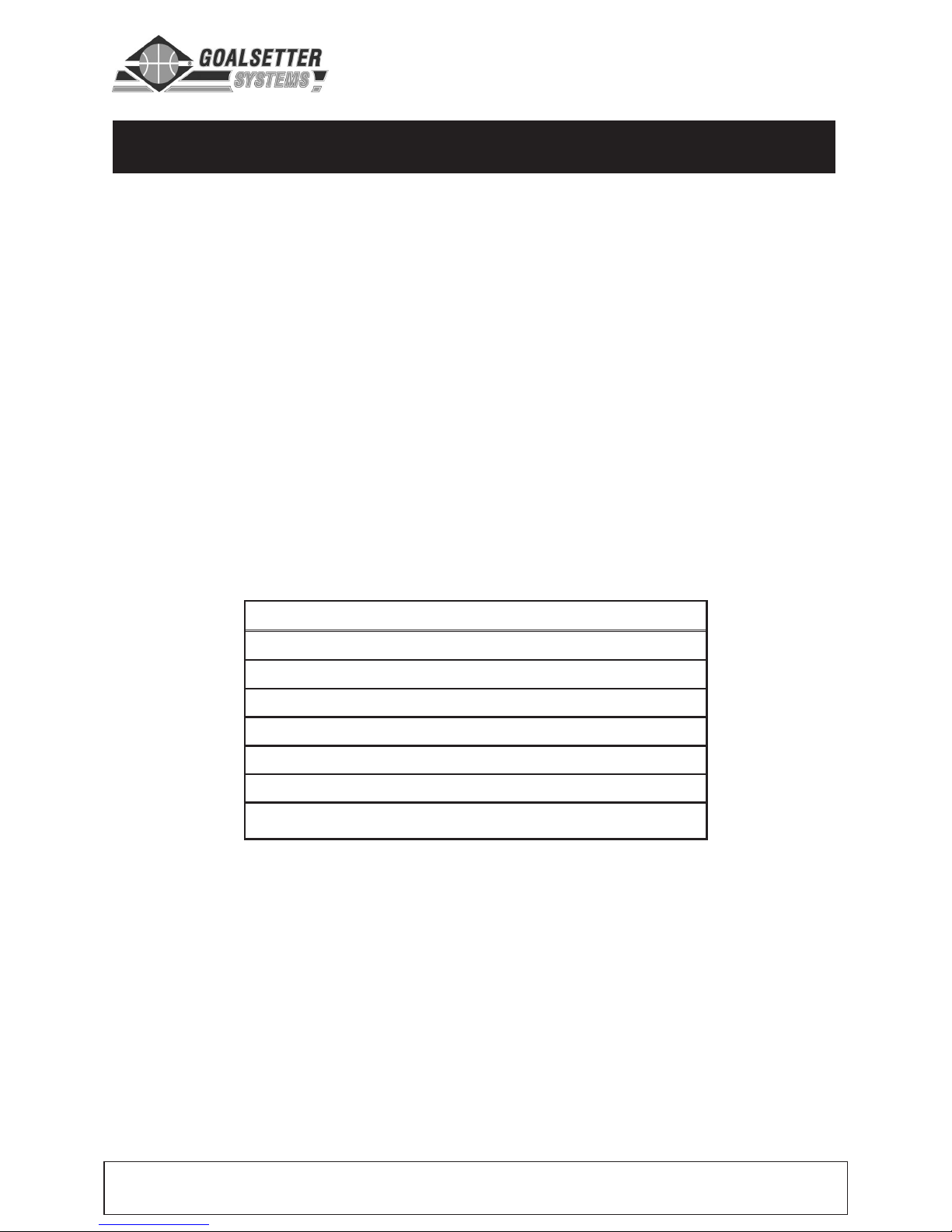
GOAL SPECIFICATIONS
Model Pole Backboard Weight Weight Height
Size Size With Acrylic With Glass Range (A)
X672 6" x 6" 42" x 72" 475 lbs. 535 lbs. 7'-10'
X660 6" x 6" 38" x 60" 460 lbs. 515 lbs. 7'-10'
X560 5" x 5" 38" x 60" 375 lbs. 430 lbs. 7'-10'
X554 5" x 5" 36" x 54" 360 lbs. 400 lbs. 7'-10'
X454 4" x 4" 36" x 54" 260 lbs. 300 lbs. 7'-10'
X448 4" x 4" 32" x 48" 255 lbs. 285 lbs. 7'-10'
Model Extension Distance (B) at: Rim to Top-of-Goal
Distance (C)
X672 33-3/4"
X660 29-3/4"
X560 29-3/4"
X554 27-3/4"
X454 27-3/4"
X448 23-3/4"
10' 8' 7'
42" 48" 46"
42" 48" 46"
36" 43" 40"
36" 43" 40"
31" 36" 31"
31" 36" 31"
Model Crank Crank (F) Pole
Distance (D) Height (E) (not used) Height (G)
X672
18" 42" – 10'
X660 18" 42" – 10'
X560 18" 42" – 9'-9"
X554 18" 42" – 9'-9"
X454 18" 42" – 9'-9"
X448 18" 42" – 9'-9"

Extreme Series Goal System Instructions
800.362.GOAL (4625) www.goalsettersystems.com 13
B
C
Playing Surface
A
G
D
E
5" & 6" - 10",
4"- 6-1/2"

Extreme Series Goal System Instructions
14 www.goalsettersystems.com 800.362.GOAL (4625)
13
PARTS LIST
3
5
NOTE: Refer to page 15
for parts descriptions.
NOTE: Refer to page
9-11 for hardware descriptions.
Backboard
Assembly
Lower
Extension Arm
Assembly Lock
Plate
Pole
10
1
Gr
ound
Anchor
4
Hardware
2
Anchor
Hinge Bolt
15
16
Rim & Net
Assembly
and
Hardware
Rim Backplate –
4" poles only
11
Upper
Extension Arm
17
Height
Decal
6
Hardware
7
Jack
Assembly
12
Hardware
4 places
–X672
–X660
–X560
–X554
2 places
–X454
–X448
Hardware
8
Hardware
9
14

EXTREME SERIES PARTS DESCRIPTION – page 15
REF X672 X660 X560 X554 X454 X448 DESCRIPTION
1 11––––G
round Anchor (6" x 6")
––11––G
round Anchor (5" x 5")
––––11G
round Anchor (4" x 4")
2a 11––––Anchor Hinge Bolt, 3/8"-16 UNC x 7"
––11––Anchor Hinge Bolt, 3/8"-16 UNC x 6"
––––11A
nchor Hinge Bolt, 3/8"-16 UNC x 5"
2b 111111N
ut, 3/8"-16 UNC
3 11––––P
ole (6" x 6")
––11––P
ole (5" x 5")
––––11Pole (4" x 4")
4a 555555Bolt, 1/2"-13 UNC x 1-1/4"
4b 555555Lock Washer, 1/2"
5 111111Assembly Lock Plate
6a 111111Bolt, 1/2"-13 UNC x 4"
6b 222222Flat Washer, 1/2"
6c 444444Nylon Washer, 1/2"
6d 1 11111Locknut, 1/2"-13 UNC
7 1 11111Jack Assembly
8a 2 2 – – ––Bolt, 1/2"-13 UNC x 11"
––22––Bolt, 1/2"-13 UNC x 10"
––––22Bolt, 1/2"-13 UNC x 8"
8b 444444Flat Washer, 1/2"
8c 888888Nylon Washer, 1/2"
8d 222222Locknut, 1/2"-13 UNC
9a 1 1 – –––Bolt, 1/2"-13 UNC x 11"
––11––Bolt, 1/2"-13 UNC x 10"
––––11Bolt, 1/2"-13 UNC x 8"
9b 2 2 2 2 2 2 Flat Washer, 1/2"
9c 222222Nylon Washer, 1/2"
9d 2222––Nylon Spacer, 1"
9e 111111Locknut, 1/2"-13 UNC
10 11––––Lower Extension Arm (6")
––11––Lower Extension Arm (5")
– – ––11Lower Extension Arm (4")
11 11––––Upper Extension Arm (6")
––11––Upper Extension Arm (5")
– – – – 1 1 Upper Extension Arm (4")
12a 4 4 – –––Bolt, 1/2"-13 UNC x 3-1/4"
– – 4 4 – – Bolt, 1/2"-13 UNC x 2-1/2"
– – ––22Bolt, 1/2"-13 UNC x 8"
12b 888844Flat Washer, 1/2", 5/8" for 4" poles
12c 4
4
4 422
Locknut, 1/2"-13 UNC
13 1 –––––Backboard Assy. – 42" x 70"
–
1
1
–
––
Backboar
d Assy
. – 38" x 60"
– ––11–Backboard Assy. – 36" x 54"
–
––––1
Backboar
d Assy. – 32" x 48"
14 111111Rim and Net Assembly
15a 444444Bolt, 3/8"-16 UNC x 2"
15b 888888Flat Washer, 3/8"
15c 444444Lock Washer, 3/8"
15d 444444Nut, 3/8"-16 UNC
16 ––––11Rim Backplate
17 111111Decal – Height Indicator

Extreme Series Goal System Instructions
16 www.goalsettersystems.com 800.362.GOAL (4625)
POLE ASSEMBLY
Step 1: Remove five plastic plugs from
threaded holes in ground anchor. Also
remove hinge bolt
3 and nut (these will
be used in Step 3.)
NOTE: Use protective padding to
protect pole finish.
Step 2: Unpack pole.
Step 3: Align pole hinge 1 with anchor
plate hinge
2 and insert bolt 3 (#2 in
parts list) and nut.
Step 4: Lift pole to appr
oximately 30º
and attach lock plate
4 to ground anchor and pole.
IMPOR
TANT
: The 30º pole installation angle MUST
be maintained until
pole is raised in Goal Alignment.
NOTE: For steps 5 and 6, refer to top graphic on facing page.
Step 5: Align lower extension arm 5 pivot with lower bushing on pole
6 . Attach arm to pole with 1/2" bolt (#8 in parts list), two flat washers,
four nylon washers and locknut.
Hardware Sequence: Bolt passes through flat washer - nylon washer - arm - nylon
washer -pole - nylon washer - arm - nylon washer -flat washer - locknut.
Step 6: Align upper extension arm 7 pivot with upper bushing on pole
8 . Attach arm to pole with 1/2" bolt (#8 in parts list), two flat washers,
four nylon washers and locknut.
Hardware Sequence: Bolt passes through flat washer - nylon washer - arm - nylon
washer -pole - nylon washer - arm - nylon washer -flat washer - locknut.
2
1
4
3

Extreme Series Goal System Instructions
800.362.GOAL (4625) www.goalsettersystems.com 17
POLE ASSEMBLY (continued)
Step 7: Attach lower end of jack 9 to bracket on pole 10 with 1/2"
x 4" bolt (#6 in parts list), two flat washers, four nylon washers and
locknut.
NOTE: Jack is packaged with pole on all Extreme models.
Hardware Sequence: Bolt passes
through flat washer - nylon washer pole bracket - nylon washer -jack
pivot - nylon washer - pole bracket nylon washer -flat washer - locknut.
Step 8: Extend jack until
upper jack bracket
11 is
aligned with holes in lower
extension arm.
IMPORTANT: Attach upper
end of jack to lower
extension arm by extending the jack; DO NOT swing arm to make
attachment.
Step 9: Attach upper end of jack 11 to lower extension arm 5 with
1/2" bolt (#9 in parts list), two flat washers, two nylon washers, two
spacers and locknut. (No spacers on 4" model.)
Hardware Sequence: Bolt passes through flat washer - nylon washer - arm - spacer
- jack bracket - spacer - arm - nylon washer - flat washer - locknut.
5
8
7
11
6
10
9

Extreme Series Goal System Instructions
18
www
.goalsettersystems.com 800.362.GOAL (4625)
BACKBOARD ATTACHMENT
IMPOR
TANT:
Pole MUST
be at
original 30º installation angle as
specified in
Pole Assembly.
Step 1: Open lid of box
containing backboar
d
1 and
position the backboard (without
removing it from box) face down
under lower extension arm
2
with rim mounting plate 3 toward
pole.
NOTE: X448 and X454 backboard
uses two 1/2" bolts and four 5/8"
flat washers for attachment; all
others use four. 5/8" washer
needs to be seated properly over
nylon bushing on outside of
backboard H-frame.
Step 2: Align backboard holes 4
with lower extension arm holes
2 . Attach backboar
d to arm with
1/2" bolt (#12 in parts list), two flat
washers and locknut at each
mounting point.
Step 3: Align backboar
d holes
5
with upper extension arm holes
6 . Attach backboard to arm with
1/2" bolt (#12 in parts list), two flat
washers and locknut at each
mounting point.
Hardware Sequence for X672 and X660:
Bolt passes through flat washer - arm
bracket - backboard bracket - arm
bracket - flat washer - locknut.
Hardwar
e Sequence for X560 and X554:
Bolt passes thr
ough flat washer - arm -
backboar
d bracket - flat washer - locknut.
Hardware Sequence for X454 and X448:
Bolt passes through flat washer - arm backboard bracket - backboard bracket arm - flat washer - locknut.
1
2
3
6
5
4

Extreme Series Goal System Instructions
800.362.GOAL
(4625)
www
.goalsettersystems.com
19
GOAL ALIGNMENT
IMPORTANT: For safe assembly, do the following:
•Use two or three people to raise the goal assembly and hold it in a
vertical position. They should be in good physical condition and
capable of lifting 80-100 lbs (35-45 kg).
•DO NOT adjust height of backboard or
attach rim until pole is raised and bolted
down.
•Correct sequence of hardware installation
MUST be followed during assembly.
Step 1: Locate five 1/2" x 1-1/4" bolts 1
(#4 in parts list). Prepare them for use by
having lock washer
2 slipped on as
shown.
Step 2: Push up on backboard to raise
goal assembly to vertical position. The
assembly lock plate, maintaining pole at
30º installation angle, will fall away. Save
lock plate for future disassembly.
Step 3: Fasten pole 3 to threaded
ground anchor plate
4 as follows:
•First, install and tighten three back
bolts
5 with lock washers.
•Second, remove ground anchor hinge bolt and nut 7 . Save for
future disassembly.
•Third, install and tighten two front bolts 6 with lock washers.
Step 4: Check goal assembly with a level and inspect visually to
determine if it is parallel and plumb to playing surface.
Step 5: If adjustments are necessary, slightly loosen bolts to rotate
goal or place shims between pole plate and gr
ound anchor plate.
Step 6: Fully tighten five bolts.
IMPOR
T
ANT
:
The bolts must pass all the way thr
ough the gr
ound
anchor plate. If they are recessed within the plate when fully
tightened, please contact Goalsetter Systems.
Both Sides
1
2
3
4
7
6
5

Extreme Series Goal System Instructions
20 www.goalsettersystems.com 800.362.GOAL (4625)
RIM ATTACHMENT
2
3
4
5
6
7
NOTE: Use all steps of the following instructions
to install a reflex rim. To install a static rim, follow
all steps except #2 and #6.
Step 1: Remove any cardboard edge protectors
and protective sheeting from backboard.
NOTE: Four steel shouldered bushings 1 are
factory installed. If loose, make sure to have them
seated properly when tightening rim bolts. If
missing, contact Goalsetter or dealer to get
replacements.
DO NOT install rim without
bushings.
Step 2: If not already removed, remove cover plate
screws
6 and cover plate 5 from rim assembly.
IMPORTANT: Correct sequence of hardware
installation MUST be followed during assembly.
Step 3: Loosely attach rim 4 to backboard
through top mounting holes
2 with two 3/8" x 2"
bolts, four flat washer, two lock washers and two
nuts. Snug tighten hardware – a 9/16" open-end
wrench may be necessary.
IMPORTANT – X454 & X448 only: When
attaching rim to TOP mounting holes, attach rim
bolt backplate
7 at same time.
Hardware Sequence: Bolt passes through flat washer - rim
backplate - backboard bushing - backboard mounting plate - flat
washer - lock washer - nut.
Step 4: Repeat pr
ocedure outlined in Step 3 for
lower rim mounting holes
3 .
Step 5: Level rim side to side and then fully
tighten har
dwar
e.
Step 6: Position cover plate 5 and attach with
cover plate screws
6 .
Step 7: Attach net to rim.
1

Extreme Series Goal System Instructions
800.362.GOAL (4625) www.goalsettersystems.com 21
HEIGHT INDICATOR ATTACHMENT
Step 1: Position top of rim 7' above playing
surface using crank handle. Measure
distance with a tape measure for accuracy.
Step 2: Peel 1/2" of backing off the top of
the decal. Slip decal under the outer tube on
the jack until the 7' line is even with the lower
end of the jack tube 1 .
Step 3: Hold decal square with the jack and
peel backing off, pressing down decal down
onto jack as backing is peeled off.
The exterior finish of your Goalsetter goal is designed for outdoor
environments and should only require periodic cleaning and inspection for
imperfections that could develop over time (see Maintenance section).
When cleaning is necessary, Goalsetter recommends using water and a mild
dish detergent applied with a soft, non-abrasive cloth.
IMPORTANT: DO NOT use abrasive cleaners to clean the goal. Damage to
the finish may result.
CLEANING
1 Crank – Turn clockwise for goal to go up,
turn counter clockwise for goal to go down.
2 Height Indicator indicates goal height from
7' to 10'.
OPERATION
1
1
2

Extreme Series Goal System Instructions
22
www
.goalsettersystems.com 800.362.GOAL (4625)
LUBRICATION
1
1 Jack Assembly
The Extreme Series goals are
equipped with a grease zerk
– use
several shots of grease.
IMPORTANT – A general-purpose
lubricating oil like “3-in-1” or lightweight
motor oil is recommended. DO NOT use
penetrating oil like “WD-40”. Goalsetter
has “Maintenance Kits” available which
would include a bottle of lubricating oil.
Contact Goalsetter Systems, Inc. or your
local Goalsetter Dealer for details.
Every jack that comes with a Goalsetter height-adjustable goal is prelubricated as it comes from the factory. With any mechanical component,
periodic inspection and service is required. Goalsetter recommends applying
lubrication at least once or twice a year to keep a smooth operation of the
height actuator. There are two lubrication service points provided. Failure to
do so could result in jack failure and not be covered under warranty.
Goalsetter uses a two-part acrylic-enamel paint on our
goals. With periodic inspection and service when
needed, the high-gloss finish is designed to last for
many years. A small bottle of black paint with brush is
provided with every goal for touch up of imperfections
as they develop and can be found in the hardware kit.
If more touch up is required, please contact Goalsetter
Systems, Inc. or your local Goalsetter Dealer.
MAINTENANCE

800.362.GOAL
(4625)
www.goalsettersystems.com 23
Buyer agrees that products sold by Goalsetter Systems, Inc. carry the following warranty:
Subject to proper installation and normal, intended use, all structural components of Goalsetter Systems
Signature Series*, Extreme Series* and GS Wall-Mount Series* basketball systems are warranted to be free of
defects in material and workmanship for the duration of ownership by the original retail purchaser, subject to
the limitations below. Tournament Series* systems will be covered by this warranty for a period of five years.
GS Portable Series* systems will be covered by this warranty for a period of two years. Goalsetter shall have
the right to require the purchaser to deliver the allegedly defective product to Goalsetter for testing, repair or
replacement. Goalsetter shall not be responsible for any expenses associated with the replacement or removal
of the product from its application for such delivery. Modification of any product by the customer, unless
approved by Goalsetter Systems, will void all warranty. Where listed as “
LIMITED”, the warranties shall cover
damage or failure that occurs during the course of
NORMAL or INTENDED USE of the product. Normal or
intended use shall be described as activity that is necessary for the participation in the sport for which the
equipment is designed.
NOT COVERED is damage caused by deliberate hanging, multiple player hanging,
vandalism, non-basketball activities or any other activity that could be regarded as abusive. Where stated as
“
UNCONDITIONAL” the warranty limitations listed above do not apply. *Signature Series – MVP, Captain, AllAmerican, All-Star, Contender, Champion; Extreme Series – X672, X660, X560, X554, X454, X448; GS WallMount Series – GS72 Wall-Mount, GS60 Wall-Mount, GS54 Wall-Mount, GS48 Wall-Mount; Tournament Series
– Elite, Classic; GS Portable Series – GS1000, GS2000, GS2500, GS3000, GS3500
The Aqua System carries a five-year limited warranty, excluding the jack which carries a two-year warranty.
Any warranty on a basketball system excludes the rim. Rim warranties are as follows: Single Ring Static
Rim: two-year limited; Double Ring Static Rim: Unconditional Lifetime; Home Court Flex Rim: one-year limited;
Heavy Duty Flex Rim: two-year limited; GS Ultra Flex Rim: five-year limited; GS Collegiate Breakaway Rim:
five-year limited; Double Ring Static Galvanized Rim: Unconditional Lifetime
Padding Warranty: Multi-Purpose Backboard Edge Padding: one-year limited; Indoor Backboard Edge
Padding: five-year limited (indoor only); Custom Fitted Pole Padding: one-year limited; Wrap Around Pole
Padding: one-year limited
NOT COVERED BY THIS WARRANTY
• Use in non-residential applications of Glass backboards on Signature Series systems.
• Use in non-residential applications of Extreme Series and Tournament Series complete systems.
• Any products subjected to abuse, negligence, improper installation, vandalism, acts of God, alteration of
product or any other events beyond the control of Goalsetter Systems.
• Paint or rusted parts. Touch-up paint is included in all hardware kits.
• Deterioration of product due to time or wear and tear.
Normal deterioration of products due to atmospheric conditions, weather, wear and tear (including paint), or
other causes that do not affect functional use are not covered by Goalsetter Systems warranties. All warranties
are valid only when product is used in the intended application & when installed according to Goalsetter
Systems instructions. Warranty will be void if maintenance instructions in the Owner’s Manual are not followed.
If you did not receive an Owners Manual please call 1-800-362-4625 and one will be mailed to you.
WARRANTY CLAIMS: All returns must be arranged through the Goalsetter Systems dealer where the product
was originally purchased. Warranties do not cover dealer service charges, labor charges and travel expenses
associated with replacement, repair or removal of warranty item. A Goalsetter Warranty Claim form must be
completed, and photos submitted, for any item you wish to claim under warranty. If the purchase was not
made thr
ough a dealer
, this form is available by email, fax or mail. In r
esponse to your claim, you will receive an
order confirmation as well as a notice stating whether Goalsetter needs your warranty item returned.
Goalsetter will notify you by fax or phone if we determine that the item cannot be claimed under warranty.
Goalsetter Systems is not responsible for any charges for labor to install or repair defective product
without prior authorization. Goalsetter will determine the most economical method to either repair or
replace product before any work is to commence.
WARRANTIES

Questions? Comments? Contact Us:
Phone: 800.362.4625 • Fax: 641.594.3343
Email: info@goalsettersystems.com
www.goalsettersystems.com
 Loading...