

Goalsetter Systems Contender Signature Series, Champion Signature Series Installation And Owner's Instructions
INSTALLATION AND
INSTALLATION AND
OWNER’S INSTRUCTIONS
OWNER’S INSTRUCTIONS
Signature Series
External Jack
Adjustable and Fixed
Height Goal System
Contender
Champion
Made in the USA
www.goalsetter.com
Table of Contents
Safety Instructions............................... 2
Goal Specifications............................. 3
Determine Installation Location............ 3
Ground Anchor Installation................. 4
Pole Assembly............................... 5
Extension Arm Attachments (adjustable).. 6
Extension Arm Attachments (fixed)...... 7
Backboard Attachment.................. 8
Goal Alignment......................... 9
Rim Attachment........................ 10
Raise and Adjust Backboard........ 11
Height Indicator Attachment....... 12
Ready to Play....................... 13
Warranties......................... 14
Safety Instructions
Owner must ensure that all installers and players know and comply
with these rules for safe assembly, installation, operation and use
of the system. Proper and complete assembly, use and supervision
is essential for proper operation of the product and to reduce
the risk of accident or injury. DO NOT ATTEMPT TO ASSEMBLE
AND INSTALL THIS PRODUCT WITHOUT FOLLOWING THE
INSTRUCTIONS CAREFULLY.
WARNING
1. Failure to follow these instructions may result in death, serious injury and/or property damage and will void the warranty.
Do not install or use this product unless the instructions
within this manual have been carefully read and understood.
2. Locate your goal away from potential dangers, including
walls, trip hazards, high-traffic areas or where a vehicle might
come into contact with goal post, backboard or rim.
To avoid severe injury or death, do not locate goal under
power lines that may come into contact with the goal as it
is raised.
3. Two or three people in good physical condition and capable of
lifting at least 90-100 lbs. (40-45 kg) each are recommended
for safe installation and assembly.
• If using a ladder during assembly, use extreme caution. Follow all
warnings and cautions on the ladder carefully.
• Installation and assembly of this product will require lifting and
bending that may result in injury to anyone not accustomed to
this type of activity.
•
Before digging for the ground anchor, check for underground
power, gas, telephone, water and other utility lines. Failure to do
so could result in serious injury. See 811 One Call Warning box on
this page for more information or call your local utility company.
• If an auger or post hole digger is used, be sure you read and follow all instructions, warnings and cautions for such equipment.
• Ensure there are no overhead power lines within a 20 ft. (7 m)
radius of the goal location.
• Climate, corrosion or misuse could result in system failure.
• Keep organic material away from the pole base. Dirt, grass, litter
etc. could cause corrosion or deterioration.
• Only use parts provided with your Goalsetter® basketball goal
system or replacement parts provided by Goalsetter Systems,
Inc. Use of other parts (a) may cause the goal system to fail, (b)
could result in death, serious injury or property damage, and (c)
will void the warranty.
• With rim set at 6’-0” playing height, the minimum operational
height is 5’-4” (1.625 m) to the bottom of the backboard.
• DO NOT CLIMB THE POLE OR HANG on the rim or any part of
the goal system. This includes the backboard, support braces
and net. The product is not designed for such use and property
damage or personal injuries such as cuts, broken bones, nerve,
spinal cord or brain injury or death could occur.
• Use caution when performing dunking activities with this product.
• During play keep players’ faces away from the backboard, rim
and net or serious injury could result.
• Players must wear a mouth guard to avoid dental injuries.
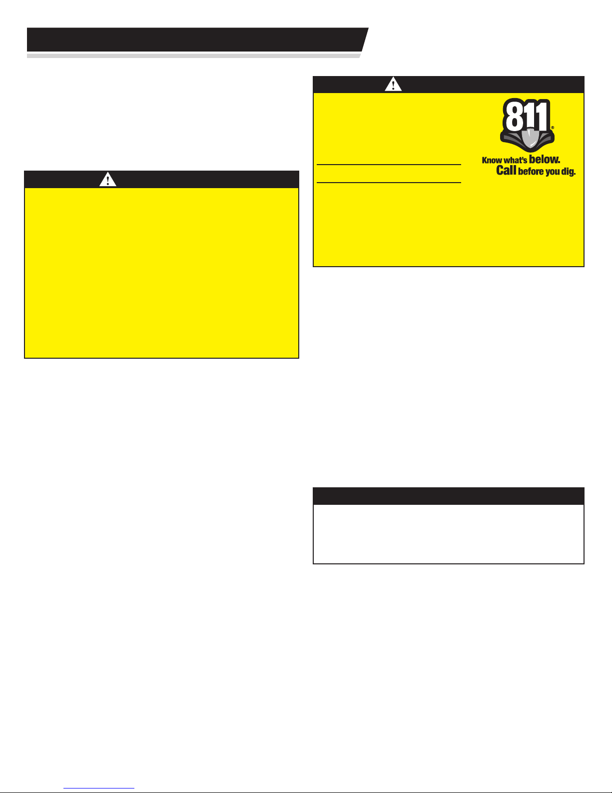
WARNING
Before digging for the ground anchor,
contact your local One-Call system
(dial 811) in your area.
Utility Markings
Color Definition
Red Electric
Yellow Gas, Oil, Petroleum
Orange Communication, Phone, TV
Blue Potable Water, Irrigation
Green/Brown Sewer
White Proposed Dig
• Do not wear jewelry (rings, watches, necklaces, etc.) or other
loose objects that could become tangled in the net or injure
another player.
•
Before each use, check the goal system for loose hardware, exces-
sive wear and signs of corrosion. Repair the system before use.
• NEVER play on damaged equipment.
•
When adjusting the system height, keep hands and fingers away
from moving parts. DO NOT allow children to adjust the system
height.
• Check the goal system frequently for signs of corrosion. Remove
surface rust and loose paint completely, and repaint with exterior
enamel paint. If rust or corrosion has penetrated or pitted any
components of the goal, DO NOT allow play and repair or replace
parts immediately.
• DO NOT use the goal system to lift or hoist anything.
• Use caution when using this goal system. Most injuries are
caused by misuse and/or not following these instructions.
1-888-258-0808
IMPORTANT
Enclosed underneath the protective sheeting on your backboard
is a warranty registration card. YOU MUST FILL OUT AND
MAIL IN THIS CARD IN ORDER TO HAVE A VALID WARRANTY.
You may also fill out a warranty registration online at
www.goalsettersystems.com.
Retain this manual for future reference of operation, maintenance
and parts information.
The information in this manual is based on the latest information
available at the time of publication. Your goal may have product
improvements and options not yet contained in this manual.
Goalsetter Systems, Inc. reserves the right to make changes at any
time without notice or obligation.
Contact the manufacturer if technical assistance is required.
Additional copies of these instructions are available from:
Goalsetter Systems, Inc.
1-800-362-GOAL (4625)
www.goalsetter.com
2
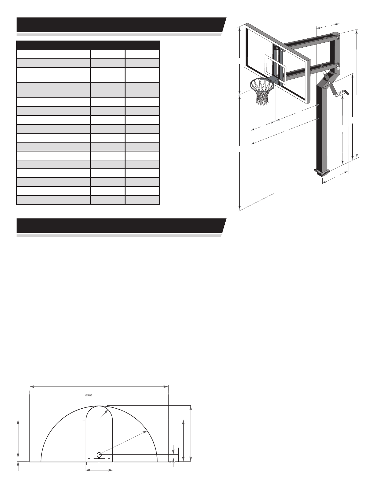
Goal Specifications
6'-0"
19'-9"
50'-0" Optimum Inside Sidelines
15'-0"
19'-0"
25'-0"
63"
15"
12'-0"
4'-0"
N
ote:
Lines are 2" wide.
J
Champion
Pole Size: 4”x4”
Backboard Size: 32” x 48”
Weight w/Acrylic: Adjustable
Fixed
Weight w/Glass: Adjustable
Fixed
290 lbs.
290 lbs.
325 lbs.
325 lbs.
(A) Height Range: 6’-10’
(B) Extension Distance: at 10’ 32”
at 8’ 36”
at 6’ 28”
(C) Maximum Overhang: 61”
(D) Distance Rim to Backboard: 25”
(E) Distance Rim to Top of Goal: 23
3
/
”
4
(F) Crank Distance:* 22”
(G) Crank Height:* 64”
(H) Offset Height: 6’-6”
(I) Pole Height: 9’-8”
(J) Offset Distance: 13
• Dimensions (F) and (G) do not apply to xed height goals.
1
/
”
2
Contender
4”x4”
36” x 54”
300 lbs.
300 lbs.
335 lbs.
335 lbs.
6’-10’
32”
36”
28”
61”
25”
3
27
/
”
4
22”
64”
6’-6”
9’-8”
1
13
/
”
2
E
A
Playing Surface
I
B
H
D
C
G
F
Determine Installation Location
Consider the following to determine where to install your
Goalsetter® Basketball Goal:
• When extended, will backboard overhang obstruct driveway or
other important space? Maximum overhang: 61” (1.5 m) from
the front of the pole to the front of the rim.
• Is there room so vehicles backing out of driveway do not strike
backboard?
• Will court markings be used?
• How much playing surface is needed?
• How much playing surface will be under the backboard?
(Having the edge of the playing surface directly underneath
the backboard can result in trip hazards and unpredictable ball
action following a shot. Try to have as much playing surface as
possible behind the backboard.)
• Other functions of playing surface (driveway, playground, etc.)
• Will the goal be at least 20 ft. (7 m) from any overhead power
lines? (No overhead power lines should be within a 20 ft.
(7 m) radius of the goal.)
• Will the ground anchor for the goal avoid underground power,
gas, telephone, water and other utility lines? (See 811 One Call
Warning box on page 2 for more information or call your local
utility company.)
Required Tools and Materials:
• Spade • Wheelbarrow
• Shovel • Cement Trowel
• Tape Measure • Stir Rod
• Level • Auger/Post Hole Digger (optional)
• Hoe •
• Water (or
10-14, 60 lb Bags of Dry Concrete Mix
1
1
/
-
/
yard of ready mix concrete)
4
3
• Rubber Mallet • Stepladder
• Steel Punch • Phillips Screwdriver
1
• 1
/
” Wrench •
8
•
9
3
/
4
” &
15
/
” Wrenches & Sockets
16
/
”,
16
1
/
” Drive Torque Wrench
2
Court Markings
(Reference Only):
Regulation Court Lengths
High School: 84’
College & Professional: 94’
3
Ground Anchor Installation
Step 1: Locate and unpack a 4” ground anchor (Item
G2440). Remove plastic plugs from bolt holes and ensure the
threads are in good condition. REPLACE THE PLUGS – they will
keep concrete and debris from the bolt holes during installation.
Leave the hinge pin in place as well.
Step 2: Determine hole location. When installed, the
edge of the ground anchor must be a minimum of 6” (15.2 cm)
away from the playing surface. Follow One Call or your utility’s
recommendations as to how close you may dig to a marked utility.
IMPORTANT
You MUST dig the anchor hole at least 48” (1.2 m) deep.
WARNING
Before digging for the ground anchor, check for underground
power, gas, telephone, water and other utility lines. Failure to do
so could result in serious injury. See 811 One Call Warning box
on page 2 for more information or call your local utility company.
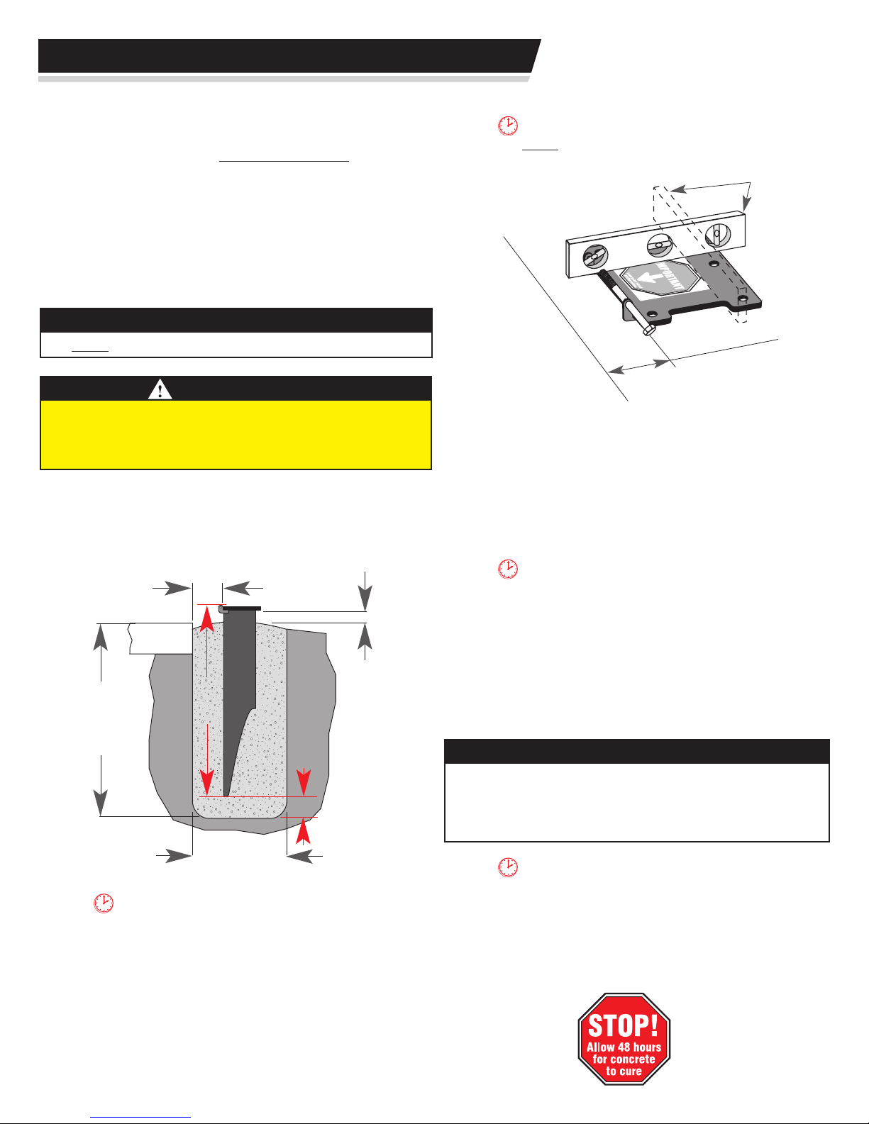
Step 3: Dig hole 48” to 50” (1.2 m – 1.3 m) deep and 14-16”
(0.35 m – 0.40 m) in diameter using a spade, shovel, auger or
post hole digger.
MUST be pointing toward the playing surface.
TIME OUT TIP: The arrow on the decal
Check level both
directions
Play
ing Surface
6" (152 mm)
minimum AND
parallel
Step 6: Position 4” ground anchor (Item G2440) in
center of hole with hinge side toward and parallel with playing
surface. Using a level, ensure the anchor is level front-to-back
and left-to-right. All edges of the ground anchor must be 6” (15.2
cm) away from all sides of hole and the top of the ground anchor
within a range of 1”- 3” (25-75 mm) above the level of the playing
surface.
6" (152 mm)
all sides
Playing
Surface
48-50”
(1.2-1.3 m)
stages, work quickly to minimize time between batches.
TIME OUT TIP: If you plan on mixing concrete in
42”
(1.1 m)
14-18”
(0.36-0.5 m)
6” (152 mm)
1”- 3” (25-75 mm) minimum
Step 4: Mix concrete. Put concrete in wheelbarrow. Add the
amount of water recommended on the bag, and mix with hoe.
insert a stir rod (such as a broomstick) into three
TIME OUT TIP: As you add concrete, occasionally
or four places in the concrete and plunge up and
down to help eliminate air bubbles.
Step 7: Continue adding concrete until concrete is within
1”- 1.5” (25-38 mm) of anchor plate bottom, or level with the
landscape – whichever comes first. Slope top of concrete away
from pole with trowel to create a smooth surface.
IMPORTANT
• Periodically re-check the level of the anchor plate in both
directions as you add more concrete.
• Slope the top of the concrete ll away from the ground
anchor in all directions to shed moisture away.
TIME OUT TIP: If you must adjust the height,
be sure to re-check level and that the anchor is
parallel with playing surface!
Step 8: If needed, adjust anchor plate height. The top of
the ground anchor should be within a range of 1”- 3” (25-75 mm)
above playing surface. Be sure to re-check level.
Step 5: Begin adding concrete into hole until concrete is
approximately 28”- 30” (.7 m – .8 m) deep.
4
Pole Assembly
IMPORTANT
• Allow 48 hours for concrete to cure before beginning.
• Check to see that no concrete or debris obstructs threads in
ground anchor bolt holes by threading anchor bolts in and out.
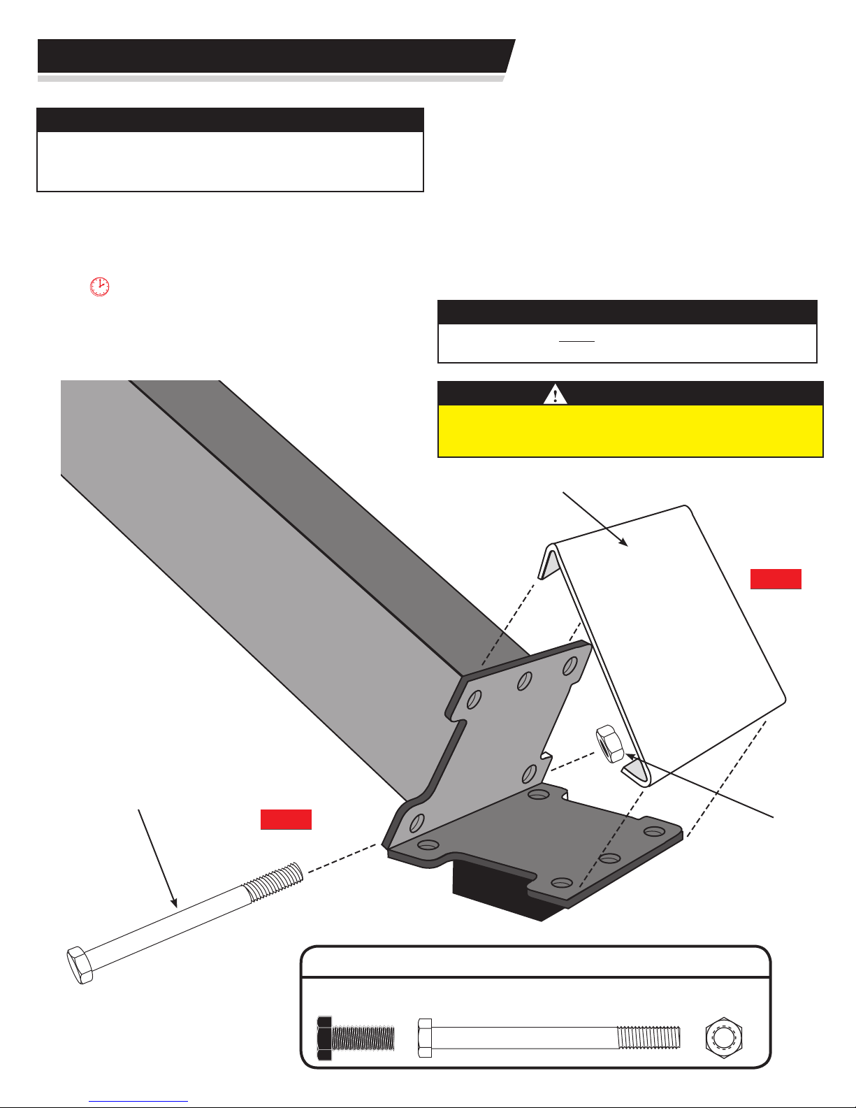
Step 1: Remove ve plastic plugs from threaded
holes in ground anchor. Also remove hinge pin and hex nut
and place near anchor plate. (These will be used in Step 3.)
packing pad (included in pole box) on the ground
at the bottom of pole. Remove once pole is held by
installation clip.
TIME OUT TIP: To protect pole nish, place square
Step 2: Unpack pole and jack (or stabilizer bar for
xed height goals). Jack (or stabilizer bar) comes packaged
with the pole.
Step 3: Align pole hinge with anchor plate hinge, then
insert hinge pin and hand tighten hex nut.
Step 4: Lift pole to approximately 30º and attach
installation clip to ground anchor and pole to maintain the
installation angle.
IMPORTANT
The installation clip MUST remain in place until pole is raised in
Goal Alignment, page 9.
WARNING
Two or three people in good physical condition and capable of
lifting at least 90-100 lbs. (40-45 kg) each are recommended for
safe installation and assembly.
Installation
Clip
Hinge
Pin
Step 3
Step 4
Hex
Nut
HARDWARE:
1
/2 x 11/4”
Anchor Bolt (1-black)
3
/8”x 5” Hinge Pin (1)
3
/8” Hex Nut (1)
5
 Loading...