

GOALRILLA B6101, DC72E1 Owner's Manual

MODEL NO.
B6101
DC72E1
BASKETBALL SYSTEM
O W N E R ' S M A N U A L
1. Read this manual carefully before starting assembly. Read each step completely before beginning
each step.
2. Some smaller parts may be shipped inside larger parts. Check inside all parts and cartons
before assembling or ordering parts.
3. Tomake assembly of your basketball system easier, use the Hardware Identifier on page 3
and 4 to identify and sort all fasteners. Check all cartons for kits. All hardware is not
located in one kit.
4. Do not tighten hardware until instructed to do so. If hardware is tightened too soon, mounting
holes may not align and parts may not easily fit together. Leave locknuts slightly loose until you are
instructed to tighten them.
An electric screwdriver is helpful in assembly. However, please set at low torque and use caution
5.
because you could overtighten the hardware and strip the screws.
Save these instructions and your proof of purchase (receipt) in the event that the manufacturer
6.
has to be contacted for replacement parts.
Please Do Not Return This Product To The Store!
Contact Escalade Sports customer service department at:
Phone: 1-888-USA-GOAL Toll Free !
Fax: 1-866-873-3536 Toll Free !
E-mail: basketball@escaladesports.com
Mailing Address:
Escalade Sports
PO Box 889
Evansville, IN 47706
Please visit our World Wide Web site at: www.G oalrilla.com
ON-LINE TROUBLE SHOOTING TECHNICAL ASSISTANCE
ON-LINE PARTS REQUESTS FREQUENTLY ASKED QUESTIONS
ADDITIONAL ESCALADE® SPORTS PRODUCT INFORMATION
®
2L-7252-06
Escalade® Sports products may be manufactured and/or licensed under the following patents.
6419596, 6179733, 5919102, 5071120, 4798381, 4424968, D326128, 8398509
Additional patents may be pending. One or more of the listed patents and/or pending patents may cover specific product.
2018 Escalade Sports
2
HARDWARE IDENTIFIER
19
/12”
-13 x 1”
Hex Bolt
(2 Pieces)
Flat Washer
3
/12”
(2 Pieces)
18
41
Pull Pin
(1 Piece)
Hardware located in 4A-7810-00 box
1/2” Split
Lock Washer
(2 Pieces)
5
1/2”X 1-1/4” Dia. Plastic-Washer
(4 Pieces)
8
5/8”-11 x 11-1/2”
Hex Bolt
(1 Piece)
4
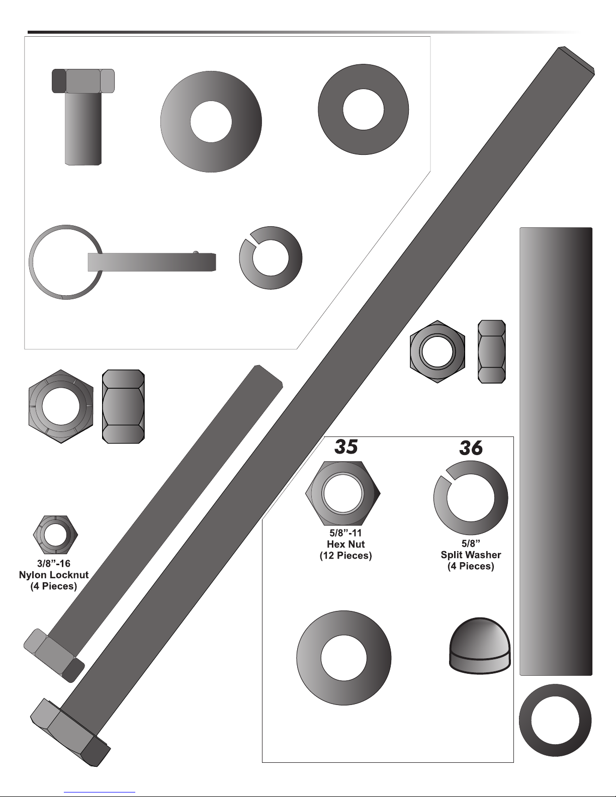
54
5/8”-11
Nylon Lock Nut (Thin)
(1 Piece)
33
1/2”-13 x 4 3/4”
(2 Pieces)
52
Hex Bolt
37
1/2”-13
Nylon Locknut (Thin)
(8 Pieces)
14
34
5/8” Thread
Protector
(4 Pieces)
5/8” Flat Washer (Thick)
(8 Pieces)
Hardware located in Anchor kit box
3
14
1” OD x 6-3/16
Pivot Tube (1 Piece)
HARDWARE IDENTIFIER
33
Hardware required for rim assembly
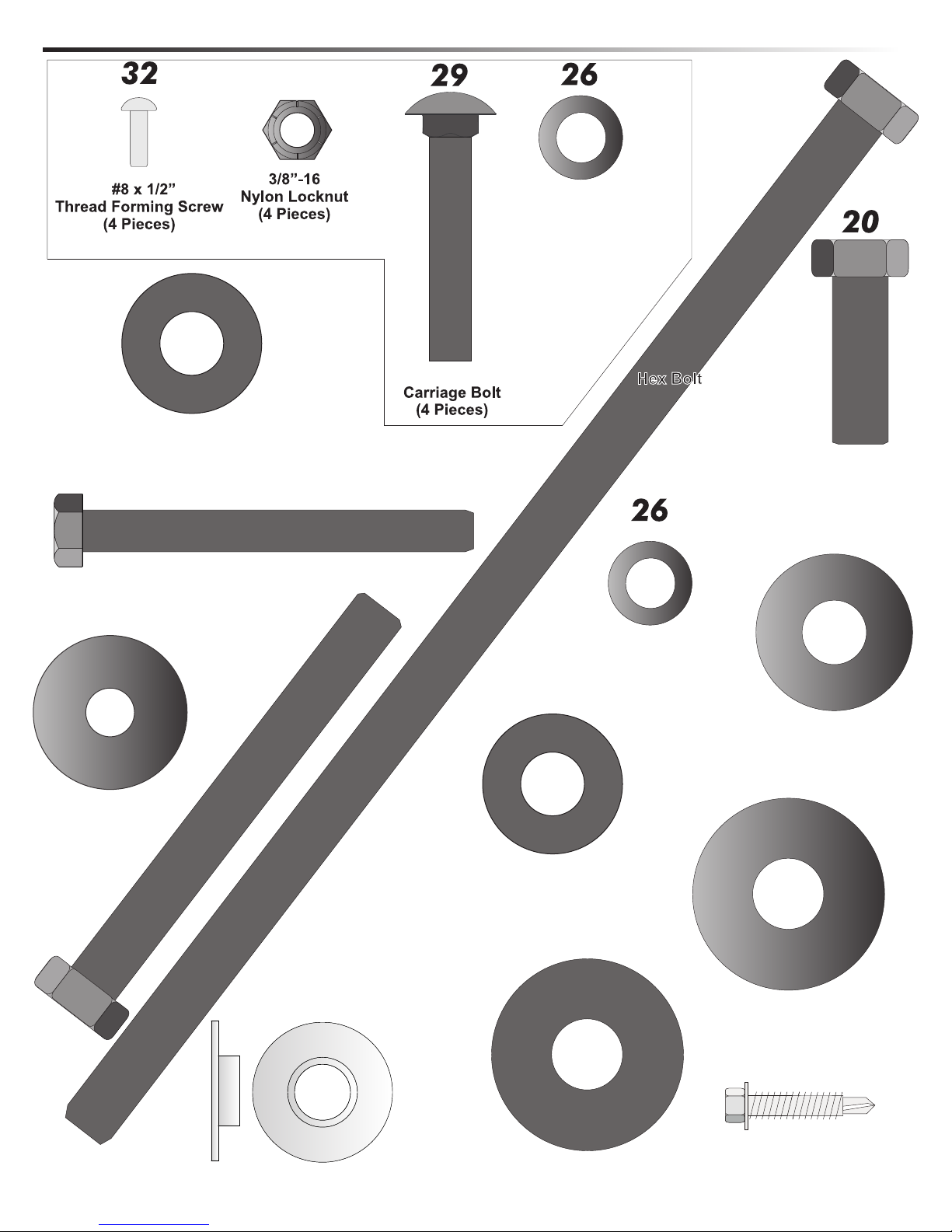
3/8” X 19mm Flat Washer
(4 pieces)
1/2”X 1-1/4” Dia.
Peel & Stick Plastic-Washer
(4 Pieces)
45
1 3/8”(OD) X 3/8”
Flat Washer
(4 Pieces)
56
46
3/8”-16 X 3-1/2”
Hex Bolt
(4 Pieces)
1/2”-13 x 4 1/4”
10
Hex Bolt
(2 Pieces)
3/8”-16 X 2”
7
1/2”-13 x 11 1/2”
(2 Pieces)
3/8” X 19mm Flat Washer
(4 pieces)
5
1/2”-13 X 1-1/2”
Hex Bolt
(2 Pieces)
3
/12”
Flat Washer
(16 Pieces)
21
22
Step Bushing
(4 pieces)
1/2”X 1-1/4” Dia. Plastic-Washer
(18 Pieces)
53
5/8” Plastic Washer
(4 Pieces)
4
5/8” Flat Washer
(2 Pieces)
51
#10 X 1 1/8” Phillips
Hex Head Self
Tapping Screw
(8 pieces)
INSTALLATION TIMELINE
1. Prior to anchor system and goal assembly, call utility services for location of underground utility lines before you dig.
2. Vertical main post assembly is a two part process.
PART 1
Day 1. Complete Anchor System Installation Instructions.
(Below)
Day 2-4. Allow concrete to cure.
ANCHOR SYSTEM INSTALLATION INSTRUCTIONS (Day 1)
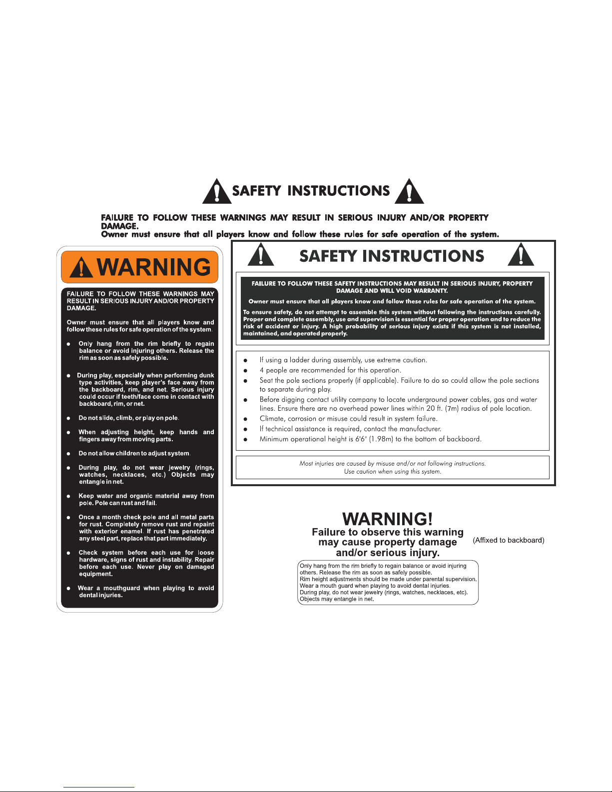
Before digging hole for anchor system, check for
buried power, gas, water, and telecommunication
lines! Failure to do so could result in serious or fatal
injury! Contact your local utility company if unsure.
Items needed for Anchor Installation (not included)
11 - 80 lb. bags of concrete (2-3 extra recommended)
1 - post hole digger (optional)
1 - 15/16” open end wrench
1 - 15/16” socket and ratchet (optional)
1 - concrete form (see note after step 2)
Note: For best results with less vibration, anchor system
should be independent of court. If pouring concrete for
both at same time, add an expansion joint in between.
Note: When digging hole, if you hit rock
and cannot dig through contact a contractor.
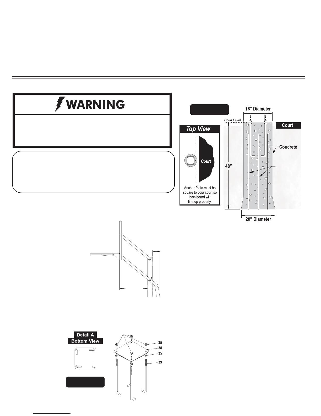
1. Determine the location of the anchor
system. The proper location is as close to
the court without making contact,
as shown in Figure 1. This,
however, is a general rule.
If you need to locate the
anchor system in a location other than
this, use the following dimensions as a
guide.
Overhang when adjusted to 10 ft. = 48”
2. Assemble anchor system as follows: Thread nut (#35) to bottom
of threads on anchor bolt (#39) insert threads of anchor bolt
(#39) through hole on anchor plate (#38) and secure with nut
(#35). Repeat this step for the remaining
anchor bolts. See
Figure 2. Note:
THESE NUTS
USED FOR
LEVELING
Each leg of
anch o r bolt s
should face the
anchor bolt to the
right. See Detail
A.
Figure 2
1 - wheel barrow
1 - garden hose
1 - level
1 - tape measure
MINI MUM
CLEA RANC E
REQU IRED
OVER HANG
18 INC H
REAR
PART 2
Day 5. Complete Goalrilla
TM
assembly instructions. (Requires
four adults)
Figure 1
Rebar
(Key #40)
Note: Using a concrete form for the top 4" of the concrete
is recommended. Cardboard forms can be purchased at
some hardware and home stores or a wooden form can
be constructed out of 2 x 4's.
Note: Failure to dig and fill hole as instructed will result
in increased system vibration.
*Tip: It is always a good idea to purchase one or two
extra bags of concrete, just in case you need them. If
extra bags are not used you can return them to the store.
3. Mix and pour concrete into hole. Follow instructions on
concrete bag. Stop about 18" below court level.
Insert four reinforcement bars (Key #40) into concrete 8"
4.
apart creating a square in center on hole.
5. Place form in desired location and finish pouring concrete
up to court level.
6. Push anchor system into concrete and agitate to work out
voids in concrete. Immediately use a level to level and square
anchor plate to playing surface. Clean off any concrete that
may be on exposed threads.
Note: The bottom four nuts will be forever embedded in
concrete. The top four nuts remain on bolts and are
used for leveling. (See Step 14 on page 10)
Let concrete cure for a MINIMUM of 72 hours.
5
GOALRILLATMASSEMBLY INSTRUCTIONS (Day 5)
TOOLS REQUIRED FOR THE FOLLOWING STEPS
1 - 15/16" open end wrench
1 - 15/16” socket and ratchet (optional)
1 - 9/16” Deep Well Socket & Ratchet
1 - 3/4” Socket & Ratchet
1 - 3/4” Open end Wrench
1 - 5-16” Socket Driver
1 - Cordless Drill & 9/64” Drill Bit
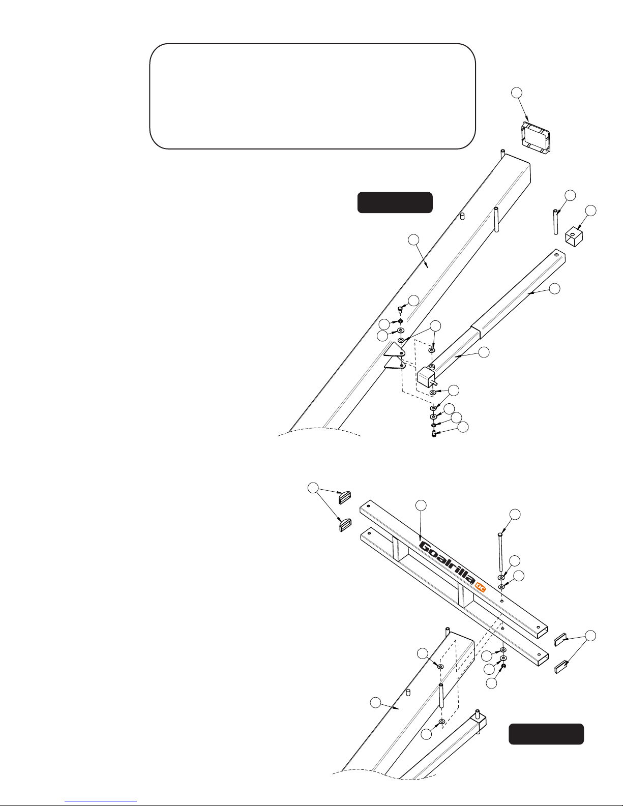
If not already pre-assembled, slide Plastic Actuator Sleeve (#15)
1.
over Steel Actuator (#16) and place Actuator Cap (#13) on top.
Slide Pivot Tube (#14) in hole near the top of Steel Actuator
and Plastic Actuator Sleeve until equal amounts stick out on
both sides of Actuator. See Figure 3.
NOTE: It may be necessary to use a rubber mallet
to tap in Pivot Tube.
1 - Level
1 - Tape Measure
1 - Rubber Mallet
1 - Set of Padded Saw Horses
1 - Ladder
1 - Pair of Safety Glasses
1 - Phillips Screwdriver
Figure 3
2
1
14
13
NOTE: It is important for the installer to understand the
necessity of the Plastic washers (#5) provided. These
washers adequately space painted parts at all pivot points.
Neglecting the use of these washers will result in rusted
parts.
2. Lay Pole (#2) on its side on two padded saw horses. Attach
Actuator (#16) to Pole (#2) using one bolt (#19), split
lockwasher (#18), Washer (#3) and two plastic washers (#5)
to thread into each side of Actuator. See Figure 3. Tighten
bolts tight.
3.
If Pole Cap (#1) is not already pre-installed insert it
into the top of the Pole (#2).
NOTE: Rounded caps
go on the front part of
the board arms.
NOTE: All board arms are made of rectangular tubing.
Tightening hardware too tight may damage tubing and
make adjustment of system difficult.
50
18
3
15
19
5
16
5
3
18
19
11
7
3
5
Attach Lower Arm (#11) to Pole (#2), as shown in Figure 4,
4.
using a Bolt (#7), two Flatwashers (#3), four Plastic Washers
(#5) and Lock Nut (#4). Do not tighten Bolt (#7) at this time.
NOTE: Make sure "Goalrilla" lettering is right side up.
DO NOT tighten bolt (#7) at this time.
5.
If Tube Plugs (#55) and (#50) are not already installed
insert them into open ends of Lower Arm (#11). Rounded
Tube Plugs (#50) go on the front end of Lower Arm (#11).
It may be necessary to use a rubber mallet to tap plugs in.
55
5
2
5
5
3
4
Figure 4
6
 Loading...