


Underwater remotely
operated vehicle for inspections
GNOM PRO
Operators manual
2017

2
TABLE OF CONTENTS
Warning !!!
Hi voltage on cable!
Do not touch the cable in a water during operation!
If any damages happen on a shield of cable it must be repaired or
changed !
Attention! AC power maximum 240V !
1. Description 3
1.1 Purpose 3
1.2 Technical specifications 4
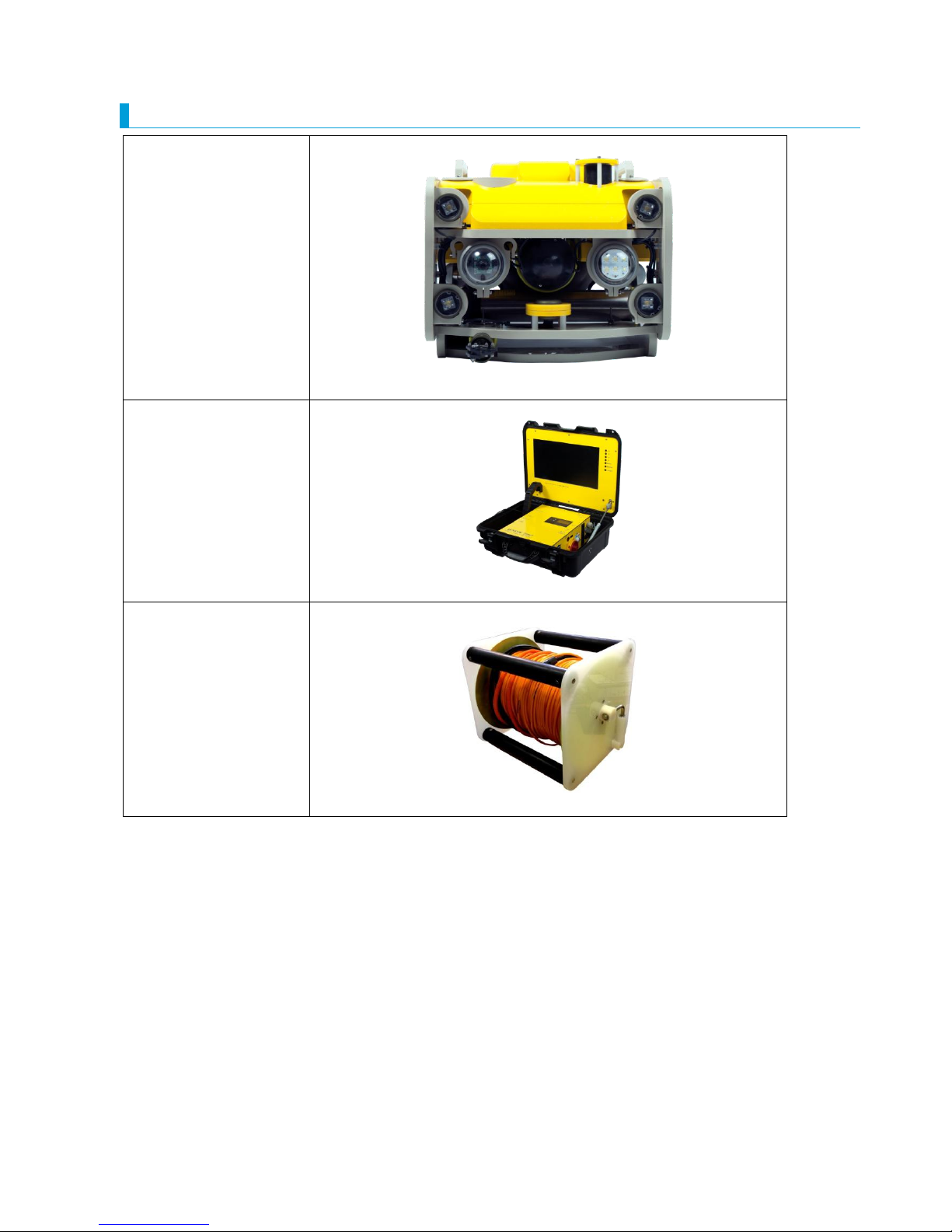
1.3 Basic complete set 5
2. User’s manual for operation with GNOM 6
2.1 Surface control module 6
2.2 Deployment 8
2.3 Operation 10
2.4 Keys and Buttons at the control panel 12
2.5 Screen modes 13
3. Maintenance operation 14
4. Safety requirements 15
5. Warranty statement 16
6. Appendix 17

3
1. DESCRIPTION
1.1 PURPOSE
LIST OF ABBREVIATIONS:
Underwater module
Surface control module
Protection polypropylene frame
Hand reel
Joystick
Digital video recorder
Computer
Monitor
Waterproof case
Grabber
sector sonar
USBL positioning system
Remotely operated underwater vehicle GNOM is intended for inspection of underwater wrecks
and other objects by video camera.
The modern computer and telecommunication technologies are used in the device, and made it easy
in handling, compact, light and inexpensive.
These solutions allowed to use flexible communication cable for transmission data, power and video
signals to/from vehicle. The special Kevlar threads have been used to improve the cable's tensile
strength. Because of this fact, the device keeps the highest degree of stabilization what is very
important for inspections. The vehicle has a good maneuverability and can easily turn on the spot.
High-effective electric motors with magnetic couplings and hi-tech electronics are used in the vehicle,
provide the fast speed of the GNOM with low power consumption.
One of the most important features of this device is a possibility to operate it from PC and via
Lan/Internet.
The GNOM, in essence, an underwater helicopter with the video-camera which moves in any direction
according to the operator's instructions.
Thrusters are DC motors which are put into the aluminium halls. The rotation transmision to the screw propeller is
realized with aid of magnetic coupling disks.
One disk is fastened at the motor's shaft in the body, and the other one – at the screw propeller's shaft inside the
cone-shaped head, which is filled up with water. The cone-shaped head may be removed by operator for cleaning
( see manual).
The vehicle is connected with the operators console via thin cable, which transmits power voltage, operation
instructions, data and video signal from the vehicle.

4
The cable with diameter 6mm is stregthened by Kevlar threads (breaking effort is 200kg) and by additional
polyehylene shield. The cable length is max up to 400m. To compensate the weight of vehicle and give neutral
buoyancy to it, the float made of foam polysyren is used, and it is put in front part of vehicle. Similar floats can be
put on the cable to change the neutral buoyancy to little positive buoyancy. Maximum operating depth of vehicle
is 150m.
Using the control pads and joystick the operator can move GNOM forward-backward, turn to the right – left, up –
down; adjust the thruster speed and the lights brightness. All data is displayed on the monitor in "TV-text" mode.
By pressing one of the buttons on the joystick the operator can pass to the menu of tuning up some vehicle's
functions – calibrating of the depth sensor and the compass as well as some other functions.
1.2 TECHNICAL SPECIFICATION
Speed:
horizontal motion, up to 1,5 m/s
vertical motion, up to 0.5 m/s
laterial motion, up to 0.5 m/s
(above numbers depend on a length of pooling cable)
Max operating depth 150 m
Power voltage 100-230VAC 2000 Watts
Operating temperature range from -5…+45°C
Operating environment humidity, up to 100%
Weight of the vehicle 25 kg
Full weight of the system 100 kg
Dimensions of vehicle 600х380х400 mm
Tether:
diameter 10 mm
length up to 400m
5
1.3 BASIC COMPLETE SET
Underwater module
Surface control
module
Hand reel with
tether
6
2. USER’S MANUAL FOR OPERATION
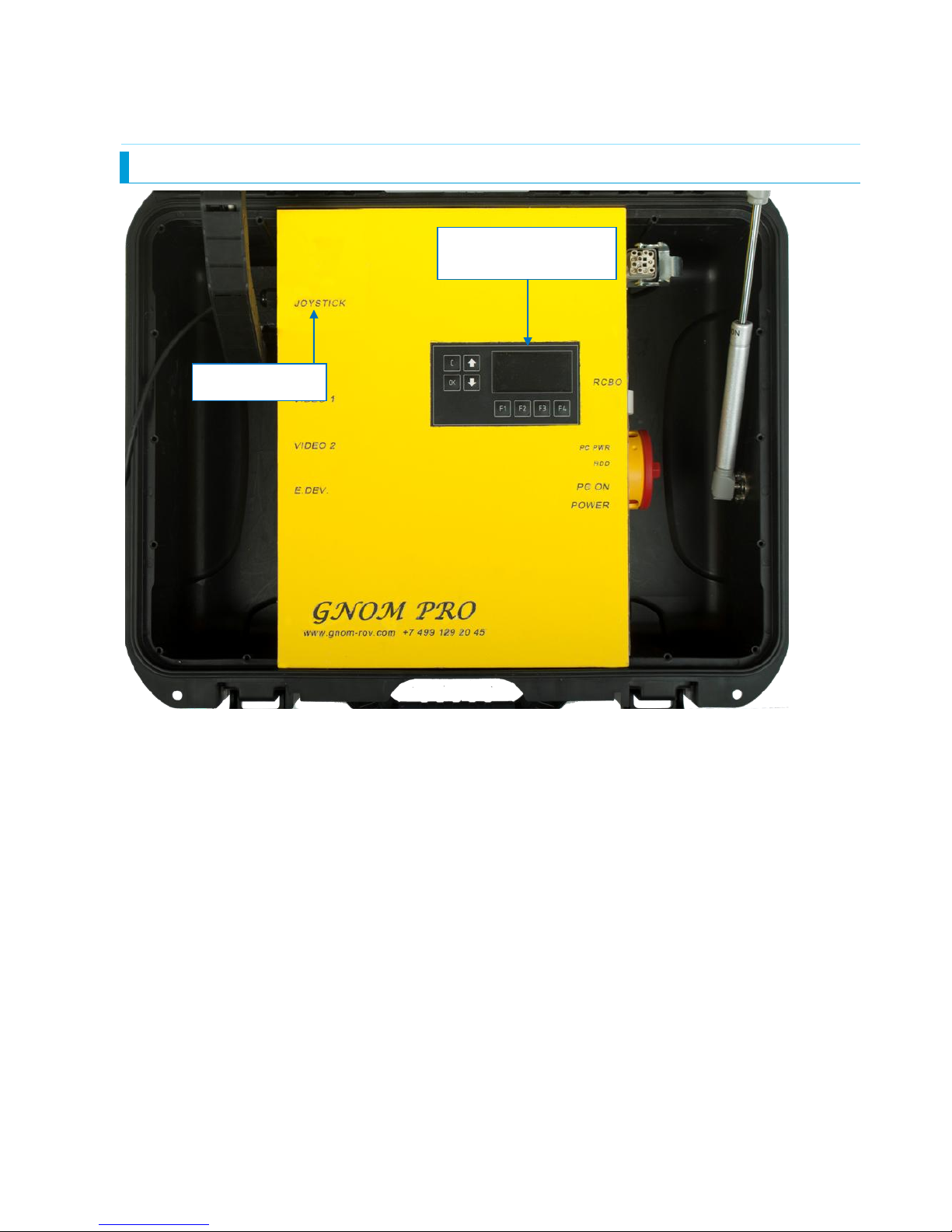
2.1 Surface control module
Front panel of module
Settings and
diagnostics menu
Joystick socket
7
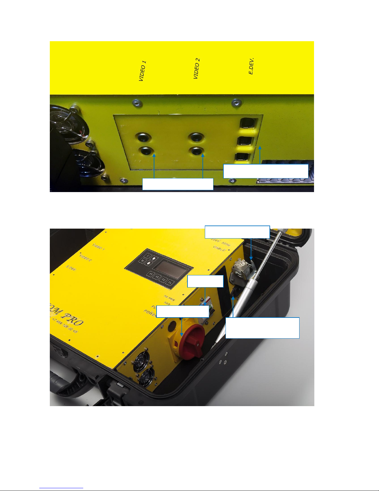
Left side of module
Right side of module
Additional videoout
Sonar communication
Tether plug
230VAC
(transformer)socket
RCBO
Power on/off

8
2.2 Deployment
Before using, please, check up all parts of vehicle especially propellers, cable and dome. Clean it if it is
necessary. Check propellers rotation by finger.
Connect underwater module. Plug in tether connector to underwater module.
Connect hand reel and Surface control module by cable.
Plug in voltage transformer to 230VAC socket and AC power cable to transformer.
Do not use ROV without transformer !
Do not rotate thrusters on air!
Do not switch lights on a full power on air!
Be very careful with cable, do not:
- stand on it
- press it
- twist it.
voltage on a cable is 360VDC! If any damages happen you must repair or change
the cable.
You can not connect to the GNOM and other devices (accessory) to the
mains with the following problems:
Wrong - incorrect wire connections L and N conductors in the appropriate
slot.
Without protective earthing conductor.
Without voltage transformer
Note. Checking the correct wiring connections (phase conductor - L)
inspects the operator. (E.g. by phase tester)
Power ON control box.
Press HOME or MODE or Central buttom (depend on model) on joystick.

9
Joystick is connected and LED is light.
After power ON you see message WELCOME. GNOM is ready for operation.
If you use GNOM in a salt water (sea) you should add weights (included in spare parts) on the
frame to change buoyancy. ROV should have neutral buoyancy for correct works.
Additional weight
Place for the weight

10
2.3 Operation.
Do not rotate thrusters on air! Do not switch lights on a full power on air!
Put the vehicle into the water.
# To move vehicle Forward/Back and turn Right/Left use
# Slow mode (SLOW). Press and adjust power gradually
(30% or 75% or 100%).
The direction and speed are indicated on an overlay.
# To move vehicle Up/Down and Laterial use
# Use arrows Up/Down to select active lights
# Simultaneously press ③ + to change the intensity of the active lights ( LOOP : 0%...100%,
100%........0%. If press ③ + + simultaneously all lights turns on/off.
# Control the GRABBER (if this is part of device) by keys /
# Control the GRABBER TURN (if available) : by arrows Left/Right
# To tilt cam Up/Down press / pads. If press + simultaneously camera goes to the
median position.
# By keys ③ + switch-on/switch off laser
# By key switch - active forward/back camera
# Autodepth mode. Press key ① to fix the vehicle at the depth you need To change the depth use
left joystick. Autodepth mode and depth are indicated on an overlay.
# Autoheading controls ON/OFF from the key (version: left joystick to left – ON, to right OFF ).
You should select forward speed then switch ON autoheading. Autoheading mode holds the speed
and direction.
# Press key ④ to select SCREEN MODES :
Mode1 or Mode2 or Mode3 (see below)
right joystick
right joystick
left joystick
R 1
R 1
R 2
R 1
R 2
L 1
L 2
L 1
L 2
SELECT
SELECT
Start

11
# Finishing the operation
To finish the operation switch power OFF then disconnect cables and pull into the reel.
Try to avoid nods and twisting of the cable.
After operation please clean propellers and shafts of motors and wash the vehicle in fresh water.
Special Functions
Sleeping mode (Power Saving Mode)
In order to save power and lengthen the using life of batteries, a power saving system is designed in
the wireless joystick. The joystick turns into sleeping mode (power saving mode) under the following
conditions:
A. If there is no operation within 30 seconds since the connection between the controller and the
receiver, the controller will turn into sleeping mode (power saving mode).
B. There is operation since the connection between the controller and receiver. If there is no operation
for 5 minutes, the controller will turn into sleeping mode (power saving mode).
Press【 or or 】 or Central button can stop this sleeping
mode (power saving mode).
ANALOG
HOME
MODE

12
2.4. KEYS AND BUTTONS AT THE JOYSTICK
L1, L2 - Camera Up/down.
L1+L2 - Camera center.
R1+R2+X - on/off all lights
R1/R2 + X –intensity of the active lights
R1, R2 – grabber control
1 ▲ - Autodepth
2 O - fixing
hor. speed
4 - Screen overlays
START - Autoheading
Up/Down – forward/reverse
Left/Right - turn
Click – slow mode
Up/Down movement
Left/Right - laterial movement
SELECT - change
active camera
Up/Down change active lights
Left/Right -
grabber rotate
HOME or ANALOG or MODE
control activation

13
2.5 SCREEN MODES / OVERELAYS
Screen 1: Full overlays.
Screen 2: depth and compass overlays only.
Screen 3: no overlays.
Current depth
Front
camera
position
Current bightness
of lights
Time
Date
Required depth
Real
direction
Rear
camera
position
Required
direction
Link status
Laser status
Active cam.
Power % and directions
of thrusters
10
10
10
10

14
3. MAITENANCE OPERATION
To maintain the vehicle it is necessary:
to clean the propellers
to rinse the vehicle in the fresh water after using in the sea
to inspect the cable after the operation. In case of any damages the cable must be
repaired or changed
to check the magnetic disk coupling regularly
Avoid nods and twisting of cable.
Within the certificate of warranty the bond (joint) mainenance manual is included.
Use it only in case of emergency, if standard maintenance is insufficient.
Before this service consult technical problems in our company on email addresses:
info@gnomrov.com
Attention:
In case of non-professional action and damage of any part, the consecutive service in our
company will be charged.

15
4. SAFETY REQUIREMENT
1. Device belongs to CLASS 1 . For this reason the power adapter must have connection
to protective earth.
2. Swith-on and swith-off the machine by main 230V switch, which is placed over the
power cord to the external control unit.
3. Do not use the system with the damaged cable.
4. Do not touch underwater vehicle and the cable if you are in water and the power is
turned ON.
5. Keep the control module and the cable reel dry.
6. When recharging the battery disconnect the vehicle and the cable reel.

16
5. WARRANTY STATEMENT
Manufacturer warrants that at the time of shipment all products shall be free from defects in material
and workmanship and suitable for the purpose specified in the product literature.
The unit/system warranty commences immediately from the date of customer acceptance and runs for
a period of 1 year. Customer acceptance will always be deemed to have occurred within 72 hours of
delivery.
Note: Any customer acceptance testing (if applicable) must be performed at either NORD SLOVAKIA
premises or at one of their approved distributors unless mutually agreed in writing prior to despatch.
Conditions:
These include, but are not limited to, the following:
1. The warranty is only deemed to be valid if the equipment was sold through NORD SLOVAKIA or
one of its approved distributors.
2. The equipment must have been installed and commissioned in strict accordance with approved
technical standards and specifications and for the purpose that the system was designed.
3. The warranty is not transferable, except or as applies to Purchaser first then to client.
4. NORD SLOVAKIA must be notified immediately (in writing) of any suspected defect and if advised
by NORD SLOVAKIA , the equipment subject to the defect shall be returned by the customer to NORD
SLOVAKIA , via a suitable mode of transportation and shall be freight paid.
5. The warranty does not apply to defects that have been caused by failure to follow the recommended
installation or maintenance procedures. Or defects resulting from normal wear & tear, incorrect
operation, fire, water ingress, lightning damage or fluctuations in vehicles supply voltages, or from any
other circumstances that may arise after delivery that is without the control of NORD SLOVAKIA. (Note:
The warranty does not apply in the event where a defect has been caused by isolation
incompatibilities.)
6. The warranty does not cover the transportation of personnel and per diem allowances relating to any
repair or replacement.
7. The warranty does not cover any direct, indirect, punitive, special consequential damages or any
damages whatsoever arising out of or connected with misuse of this product.
8. Any equipment or parts returned under warranty provisions will be returned to the customer freight
prepaid by NORD SLOVAKIA
9. The warranty shall become invalid if the customer attempts to repair or modify the equipment without
appropriate written authority being first received from NORD SLOVAKIA .
10. NORD SLOVAKIA retains the sole right to accept or reject any warranty claim.
11. Each product is carefully examined and checked before it is shipped. It
should therefore be visually and operationally checked as soon as it is
received. If it is damaged in anyway, a claim should be filed with the courier
and NORD SLOVAKIA notified of the damage.
Note: NORD SLOVAKIA reserve the right to change specifications at any time without notice and
without any obligation to incorporate new features in instruments previously sold.
Note: If the instrument is not covered by warranty, or if it is determined that the fault is caused
by misuse, repair will be billed to the customer, and an estimate submitted for customer
approval before the commencement of repairs.

17
11. ANNEX
PROBLEMS SOLUTION
Alight LED on control
unit
Check that control unit is connected to a power supply
Check that control unit is switch on
If previous conditions are met but LED is still alight, check network fuse of
control unit
Underwater unit does
not respond to
JOYSTICK
Check that control unit is switch on – LED must illuminate
Check that joystick is switch on
Check batteries in joystick
Underwater unit
does not swim
directly
Check horizontal thrusters – propellers have turn easy– check by finger
In case that some propeller turns hard, clean slide bearing of coupling axis of
propeller and check setting of coupling
Underwater unit does
not respond correctly
to Joystick
You have probably switch on function MAKRO on joystick ( some of models).
Resolve problem in according to the procedure in chapter JOYSTICK
DESCRIPTION
The screen displays
incorrect value of
navigation depth
Make calibration of depth sensor in according to this manual
Underwater module
does not respond
to joystick
Joystick is in sleep mode (power saving).
See chapter USER’S MANUAL FOR OPERATION
The monitor screen is
black. There is no
picture
Check the connection between the monitor and the control unit. See images in
the manual.
When connection is OK, check setting of the monitor – THE CHOICE OF INPUT
SIGNALS – see the manual for the monitor

18
11. ANNEX
SERVICE COUPON
Coupon No.1
Date of sale
SERIAL NUMBER
DATE OF INSPECTION
TRUE
FALSE
DESCRIPTION OF REPARATION
HORIZONTAL THRUSTER L
HORIZONTAL THRUSTER
R
VERTICAL THRUSTER F
VERTICAL THRUSTER B
LIGHTS
SERVO COMPASS
DEPTH SENSOR
JOYSTICK CONTROL UNIT
MOTOR COUPLING
STAMP AND SIGNATURE
Coupon N.2
Date of sale
SERIAL NUMBER
DATE OF INSPECTION
TRUE
FALSE
DESCRIPTION OF REPARATION
HORIZONTAL THRUSTER L
HORIZONTAL THRUSTER R
VERTICAL THRUSTER F
VERTICAL THRUSTER B
LIGHTS SERVO
COMPASS
DEPTH SENSOR
JOYSTICK
CONTROL UNIT
MOTOR COUPLING
STAMP AND SIGNATURE
Coupon No.3
Date of sale
SERIAL NUMBER
DATE OF INSPECTION
TRUE
FALSE
DESCRIPTION OF REPARATION
HORIZONTAL THRUSTER L
HORIZONTAL THRUSTER R
VERTICAL THRUSTER F
VERTICAL THRUSTER B
LIGHTS
SERVO COMPASS
DEPTH SENSOR
JOYSTICK CONTROL UNIT
MOTOR COUPLING
STAMP AND SIGNATURE
Coupon No.4
Date of sale
SERIAL NUMBER
DATE OF INSPECTION
TRUE
FALSE
DESCRIPTION OF REPARATION
HORIZONTAL THRUSTER L
HORIZONTAL THRUSTER R
VERTICAL THRUSTER F
VERTICAL THRUSTER B
LIGHTS SERVO
COMPASS
DEPTH SENSOR
JOYSTICK
CONTROL UNIT
MOTOR COUPLING
STAMP AND SIGNATURE

19
11. ANNEX
Year of purchase:
TABLE № 1. Registration of working time
Start and end date of
executed works
Place of works
Underwater unit working
time (hours)
Operator name and
signature

20
11. ANNEX
Table No. 2 Statistics of damaged and replaced fuses in control unit
Date / time of fuse
seasoning and her
replacements
Type and
parameter of
network fuse
Type and parameter
of power cable fuse
+180V
Operator name and
work position
Signature
1.
2.
3.
4.
5.
Table No. 3 Inspection of coaxial cable intact
Date
Type of cable
Result
Name
Signature
1.
2.
3.
4.
5.
Table No. 4 Inspection of grounding cable clamp resistance
Date
Type of cable
Result
Name
Signature
1.
2.
3.
4.
5.

21
11. ANNEX
Protocol of perform warranty repairs
Client
Address
Client’s agent name
Name of employee taking complaint
Date of taking complaint
Date of product sale
Type of product + serial number
Description of defect by client
Description of defect by service
operator
Used material
Legitimate complaint
Yes
No
If no legitimate - reason
Date of repaired good expedition to
client
 Loading...