

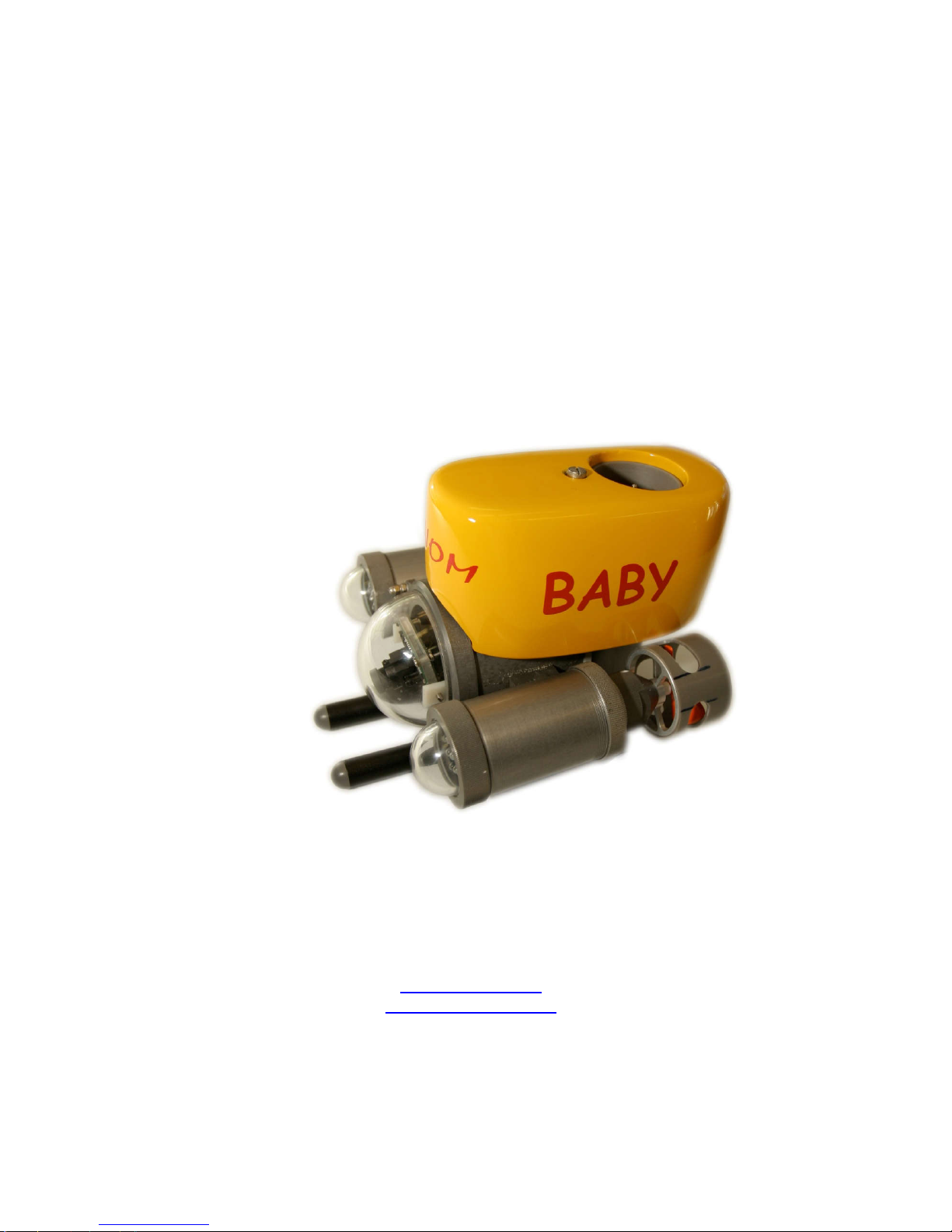
Underwater
remotely operated vehicle
GNOM BABY
Operators manual
VFTECH s.r.o.
Vapenicka 24, 971 01 Prievidza, Slovakia
Tel/Fax +421 46 54264 56
odbyt@vftech.sk
http://www.vftech.sk
2015

v05/2016
2
TABLE OF CONTENTS
1. Description 3
1.1 Purpose 3
1.2 Design 4
1.3 Technical specifications 6
2. User’s manual for operation with GNOM 7
3. Keys and Buttons at the control panel 12
4. Screen modes 15
5. Calibration 16
6. Maintenance operation 17
7. Safety requirements 18
8. Warranty statement 19
9. Examples of linking modules 20
10. Appendix 21
11. Annex 26
v05/2016
3
1. DESCRIPTION
1.1 PURPOSE
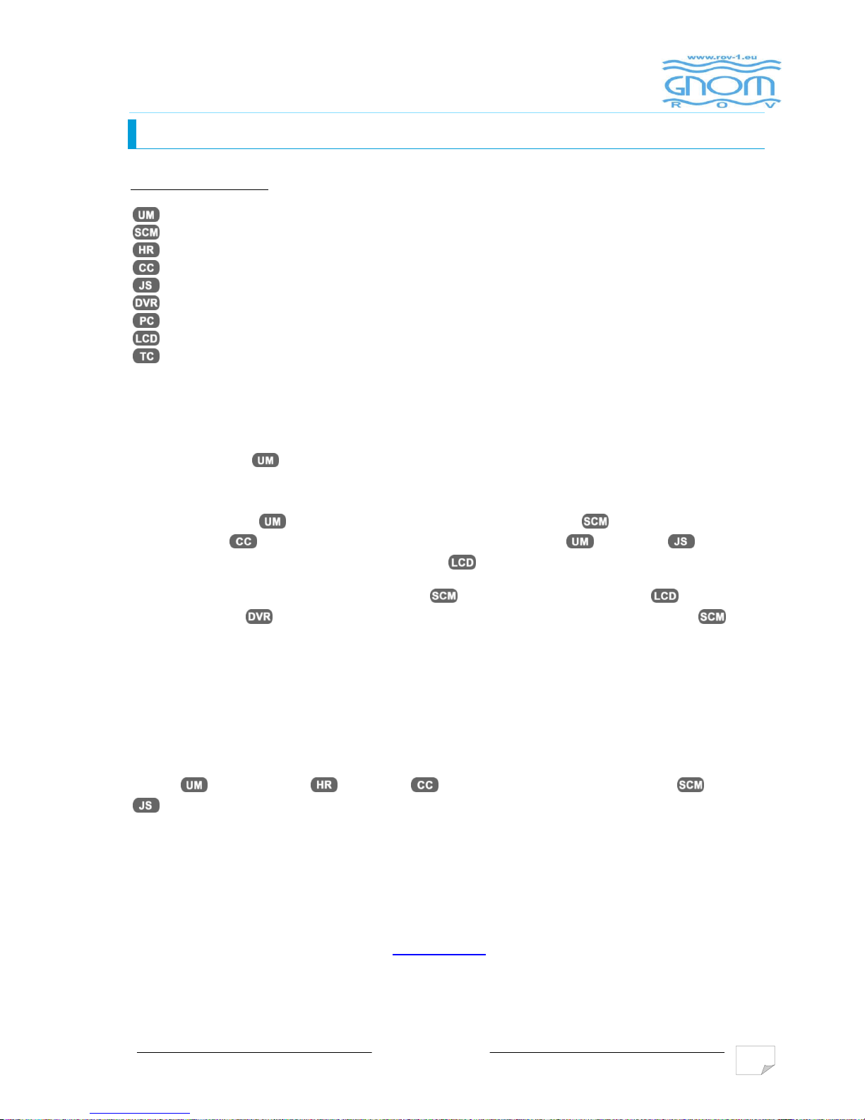
LIST OF ABBREVIATIONS:
Underwater module
Surface control module
Hand reel
Coaxial cable
Joystick
Digital video recorder
Computer
Monitor
Waterproof case
ROV Gnom Baby is intended for inspection of underwater objects such as wrecks, ship
underwater parts, propellers and different underwater constructions.
ROV Gnom Baby has a small color camera with tilt function. Two clusters of ultra-bright
LEDs are installed at both sides of the underwater module. The module has horizontal and
vertical thrusters which allow the movement of underwater module in all directions. The
underwater module is operated from the surface control module and is linked with it by
umbilical cable . The operator controls the underwater module by joystick according
to video and data from sensors on the TV screen . Maximum operation depth is 50 m.
The video signal from surface control module can be connected to monitor , TV receiver
or video recorder (if delivered) via standard AV cable. At surface controle module there
are two output connectors with video signal, what allows connect at the same time two display
units, or one display unit and a video recorder.
The power supply of surface control module is 110-230VAC 50Hz or 12-24VDC from battery with
inverter 12VDC/230VAC can be used. Maximum power consumption is 200 Watt. Battery
operation time (12 Ah) is more than 1 hour.
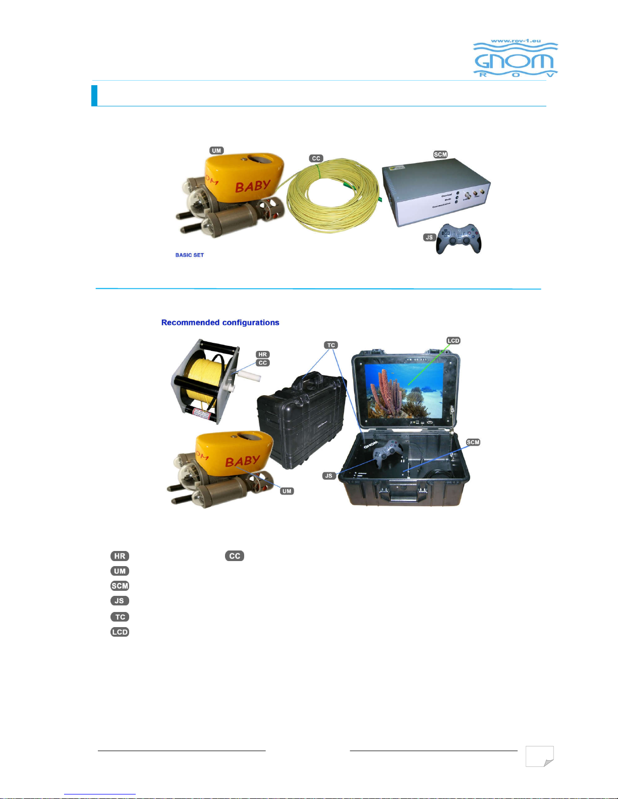
The complete system can be integrated into two plastic cases. One case contains the underwater
module and cable reel with cable , the other contains control module , joystick
and accessory equipment (monitor, video recorder - if delivered).
The size of operating area is limited by cable length (35 m in basic set). It is possible to increase
the cable length up to 75 m. The video camera together with lights provides 15-20 m daylight
visibility in transparent water. Maximum 3-4 m visibility can be reached during the night.
LCD display ot videorecorder can be installed upon request.
For update info please visit our web site www.vftech.sk
v05/2016
4
1. DESCRIPTION
1.2 DESING
Recommended configurations
Hand reel +
Coax. cable
Underwater module
Power supply/control module
Joystick
Transportation waterprof cases
LCD

The system consists of underwater vehicle, cable and
contains aluminum waterproof cylindrical hull
thruster
.
A glass dome
front part of the vehicle. Two
hull. The plastic
floatation block
the end of thrusters’ axis. All the electronic parts (the power supply converter, electronic m
and depth sensor) are installed into main cylindrical hull. Communication tether is placed at the
back roof of the hull together with depth sensor membrane.
There are protective plastic feet
of the vehicle using additional metal weights.
Thrusters are DC motors and located inside waterproof hulls. The rotation transmission to
the screw propeller performed with an aid of disk magnetic coupling. One disk is fastened at the
motor’s
shaft inside the thruster’s hull and another one at the screw propeller’s shaft inside the
cone-
shaped cap filled up with water. The cone
user for cleaning.
v05/2016
1. DESCRIPTION
–
with a side wall
with a color camera based on a 1/3” CCD matrix locates at the
horizontal thrusters
with lighters
are fastened to the main
fastened by nut and screw
.
Screw propellers are installed at
under the vehicle that are used to adjust for the
-
shaped cap can twisted off (with an effort) by a
5
with a fastened vertical
odule
buoyancy

v05/2016
6
1. DESCRIPTION
The vehicle is connected with the operator’s module via thin coaxial cable which transmits power
voltage (48V), operation commands, data from all sensors and video-signal.
The plastic cable reel with a moving lift point allows to reel in/out the cable during the
operation. The cable is strengthened by the Kevlar threads and the additional polyethylene shield.
The central cable core has 48V voltage. The power supply module has the short circuit
protection.
Surface module is mounted in a separate case and consists of power supply module,
control module and joystick. LCD display and battery 12V/7(12Ah) can be added to the basic set
of equipment upon request. Module has standard RCA jack for connecting to TV or audio/video
recorder.
Using the control pads and joystick the operator can move GNOM forward-backward, turn
to the right-left, up-down; adjust the thruster’s speed and the lighters’ brightness. All the data are
displayed in TV-text mode. By pressing one of the bottoms on the joystick the operator can pass
to the menu of tuning up some vehicle’s functions such as calibrating of the depth sensor.
1.2 TECHNICAL SPECIFICATION
3 magnetically coupled thrusters
Operation time - 500 h
Speed: - horizontal – up to 1 m/sec
vertical - up 0,3 m/sec
Operation depth – 50 m, ( can be modified up to maximum depth – 100 m)
Cable length max. – 75 m
Cable is strengthened by the Kevlar threads and the additional polyethylene shield,
negatively buoyant
Cable diameter –4.2 mm, breaking effort – 90 kg
Two clusters of ultra-bright LEDs
Color camera PAL CCD 1/3", 720 TV Lines, 0.1 lux
Power supply and surface control unit
Power supply – 230VAC or 12-24VDC battery 12V/7(12Ah)
Voltage value is displayed on a screen
Operating environment humidity – up to 100%
Operating temperature range – -5 …+ 45º. С.
Complete system is packed in two high-performance waterproof STORMCASE
ROV weight – 1.7 kg, full weight of system – 8 kg
Vehicle dimensions 210х185х150 mm
Depth sensor (sensibility 10 – 20 cm) with TV-text overlay on a screen, autodepth mode
Compass with TV-text overlay on a screen, autoheading mode
Vehicle has slight positive buoyancy, adjusting by adding metal weights

v05/2016
7
2. USER’S MANUAL FOR OPERATION
The central cable wire has 48V voltage! If any damages happened you
must repair or change the cable
2.1. Before using, please, check up all parts of vehicle especially propellers, cable and dome.
Clean the vehicle if necessary, check propeller rotation.
2.2. Adjust the buoyancy of the vehicle if necessary adding additional weights on the plastic feet
(Note that cable weight in water is approximately 2 g/m)
2.3. Plug in 3-sockets connector to reel and video cable to monitor video input. If you work from
230 VAC, connect AC power cable.
Do not rotate thrusters on air!
Do not switch lights on a full power on air!
Be very careful with the cable, do not:
Stand on it
Press on it
Twist it
2.4. If use any additional display or audio/video recorder, please, connect video cable to RCA
jack of additional video device

v05/2016
8
2. USER’S MANUAL FOR OPERATION
2.4.1 - You can not connect to the GNOM and other devices (accessory) to the
mains with the following problems:
• Wrong - incorrect wire connections L and N conductors in the appropriate slot.
• without protective earthing conductor.
Note. Checking the correct wiring connections (phase conductor - L) inspects the
operator. (E.g. by phase tester)
2.4.2 Checking the RCD
Carry out before any underwater operation at the new location as follows:
• If the requirements of paragraph 2.4.1 are met and connect to the power supply
only power module
• Switch on mains voltage button on the control panel
• After 5 seconds press the "TEST" button on the residual current device. It would
immediately lead to a safe shutdown of module
• Switch off the mains voltage button on the control panel. Switch on the current
circuit breaker
• Again switch on the power supply button on the control panel. Residual current
device must remain switched on.
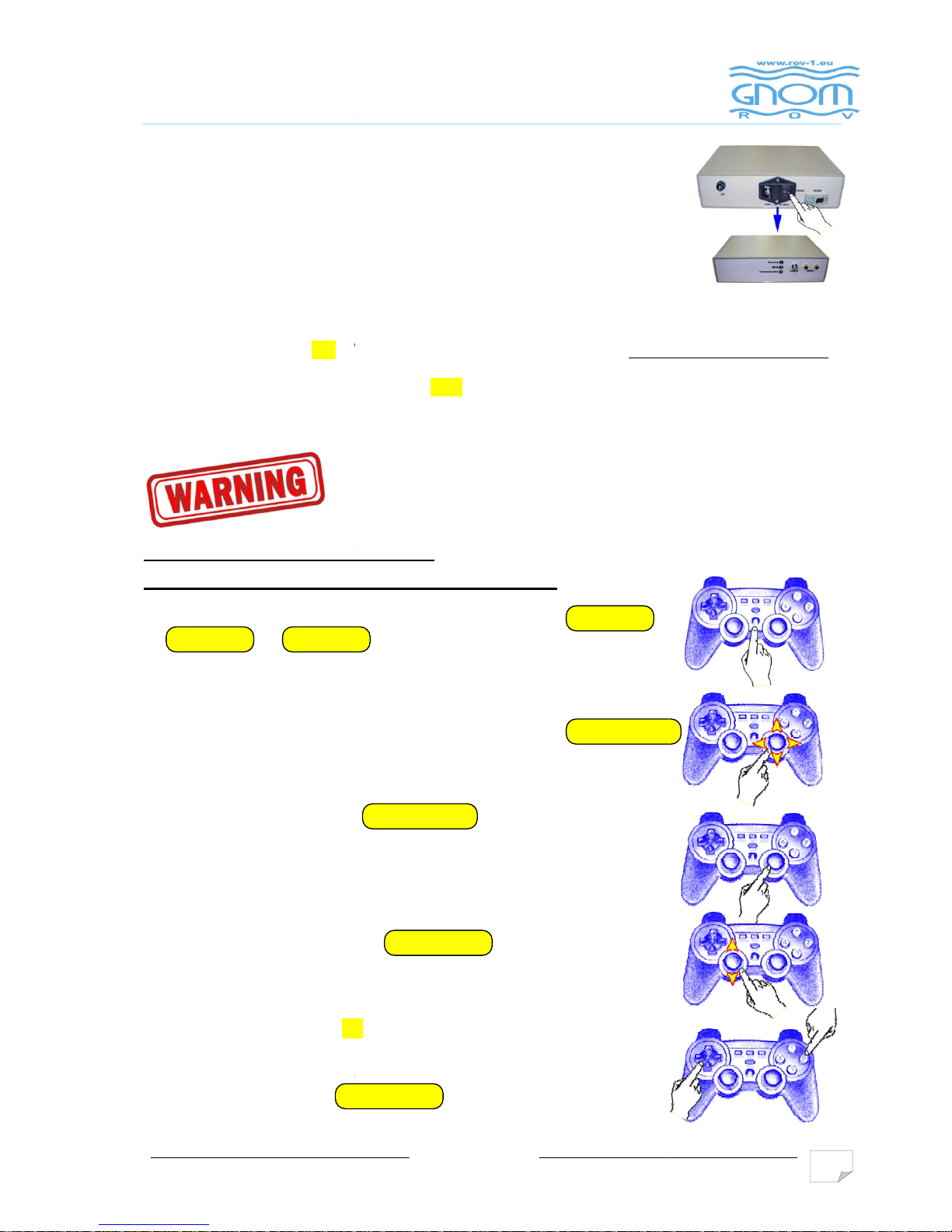
2. USER’S MANUAL FOR O
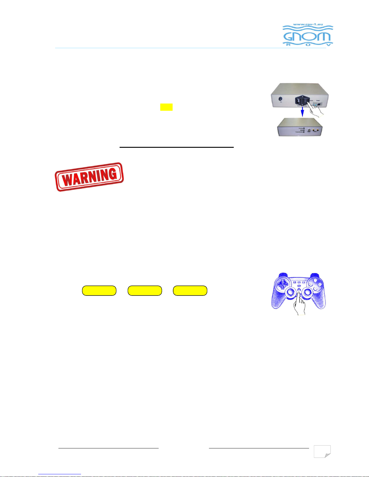
2.5. Power supply from 2
3
Set switch 230V ON
(UP position)
2.6.
If use LCD display switch on its power supply separately. Brightness,
contrast and color saturation can be adjusted manually (see the user’s
manual LCD display).
For monitor operation (TV) follow manual to the
appropriate monitor.
2.7. After switch power ON “
WELCOME
After
finish operation set switch 230V in
2.8. Operation
Do
not rotate thrusters on air!
Do not switch lights on a full power on air!
Put the vehicle into the water. To start operation press key
or on a joystick
All control functions are
displayed on a console draw (see below).
# To move vehicle
Forward/Back
# Slow mode (SLOW).
Press
(25%, 50%, 75%, 100%)
You can adjust
speed gradually (128 grades) pressing the joystick. The
direction and speed are indicated on an overlay.
# To move vehicle Up/Down
use
# Jump mode - Also press
②
A
llows to push vehicle slightly for a distance 30
chose the jump direction press arrows (
adjust the jump power use
left joystick
HOME
MODE
v05/2016
0V
WELCOME
” is displayed on monitor.
Gnom is ready for operation
OFF position
or
and turn Right/Left use
and adjust power gradually
.
to adjust the Jump mode.
– 50 cm them stop. To
Left/Right, Up/Down). To
.
left joystick
right joystick
right
joystick
ANALOG
9
.

2. USER’S MANUAL FOR O
# Simultaneously press ③+
lights ( LOOP : 0%
100%, 100%
simultaneously 100% brightness turns on
( Simultaneously press ③+
mounted )
# Control
the GRABBER (if this is part of device)
by keys /
# To tilt cam Up/Down press
If press +
simultaneously camera goes to the
position.
# By keys ③ +
switch
# Autodepth mode.
Press key
actual depth you need.
To change the depth use left joystick.
Autodepth
mode and depth are indicated on an overlay.
# Autoheading
controls ON/OFF from the
joystick to left –
ON, to right OFF ). You should select forward speed
then switch ON autoheading. Autoheading
and direction.
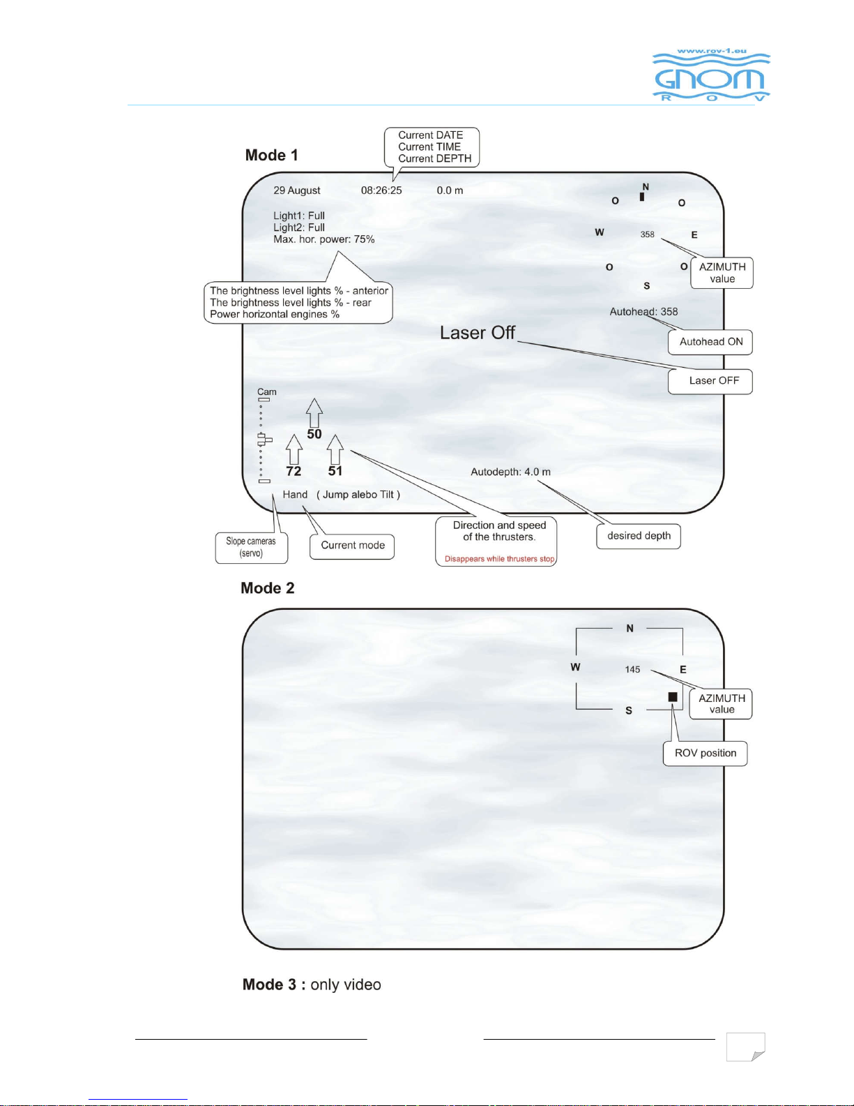
# Press key ④ to
select SCREEN MODES :
Mode1 or Mode2 or Mode3
(see below)
SELECT
L 1
L 2
R 1
R 2
v05/2016
to change the intensity of the front
. If press ③+ +
/off.
adjust rear lighters – if it is
/ pads.
median
-on/switch off laser
① ON/OFF to fix the vehicle at the
key (version: left
mode holds the speed
Start
L 1
L 2
R 1
R 1
R 2
R 2
10
v05/2016
11
2. USER’S MANUAL FOR OPERATION
# You can choose the menu language (Russian/English)
2.9. Finishing the operation
To finish the operation switch power OFF then disconnect cables and pull
into the reel.
Try to avoid nods and twisting of the cable.
After operation please clean propellers and shafts of motors and wash the vehicle in fresh
water.
Special Functions
Sleeping mode (Power Saving Mode)
In order to save power and lengthen the using life of batteries, a power saving system is designed
in the wireless joystick. The joystick turns into sleeping mode (power saving mode) under the
following conditions:
A. If there is no operation within 30 seconds since the connection between the controller and the
receiver, the controller will turn into sleeping mode (power saving mode).
B. There is operation since the connection between the controller and
receiver. If there is no operation for 5 minutes, the controller will turn into
sleeping mode (power saving mode).
Press【 or or 】button can
stop this sleeping mode (power saving mode).
ANALOG
HOME
MODE

v05/2016
12
3. KEYS AND BUTTONS AT THE CONTROL PANEL

v05/2016
13
3. KEYS AND BUTTONS AT THE CONTROL PANEL

v05/2016
14
3. KEYS AND BUTTONS AT THE CONTROL PANEL
v05/2016
15
4. SCREEN MODES
v05/2016
16
5. CALIBRATION
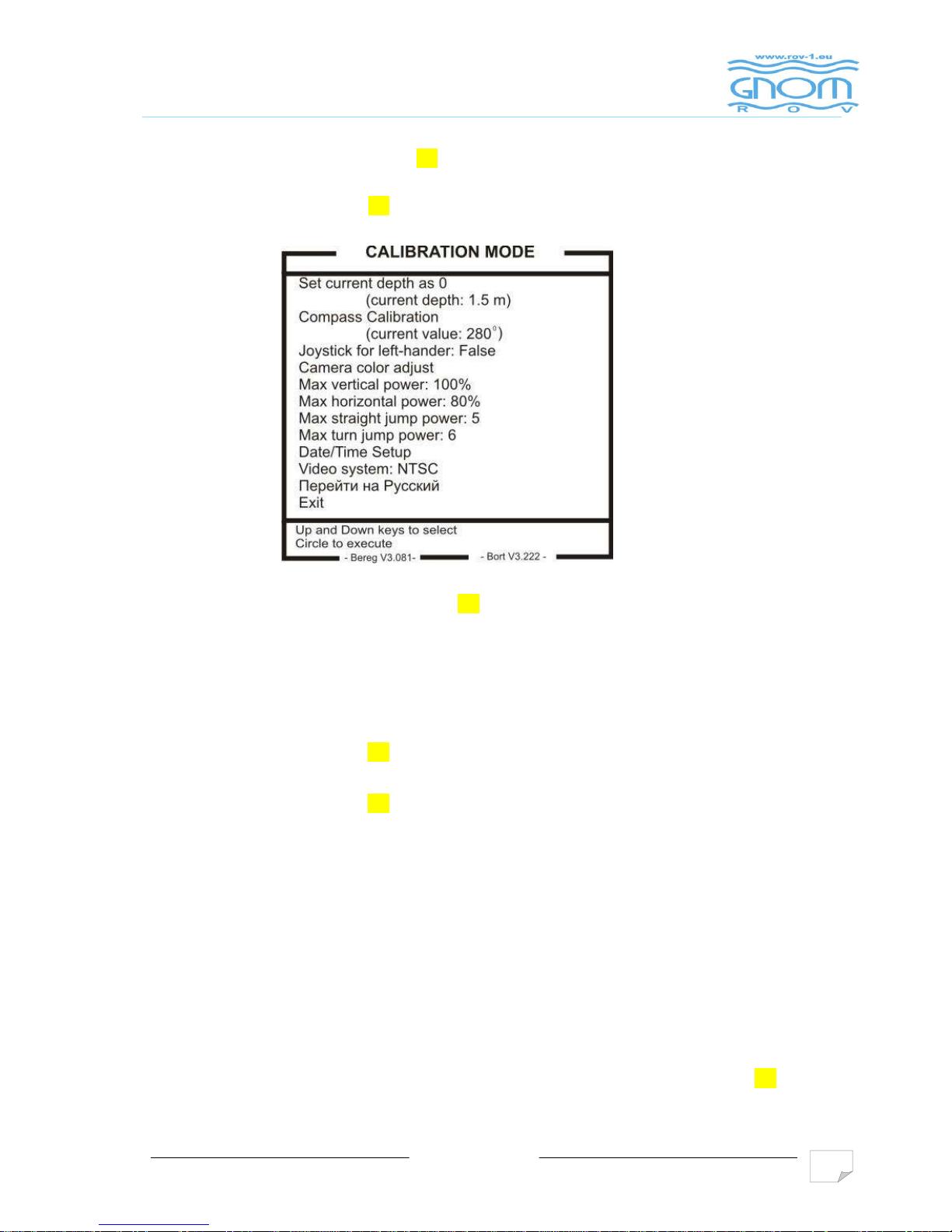
To enter this mode you should be in start mode (message WELCOME is indicated). To calibrate depth
sensor and compass you should press key ③ and hold it for 7-8 sec only while message WELCOME is
indicated. Message "Calibration mode" appears. To select function you should use left arrows. To enter
functions you should use right key ②
- “Set current depth as 0”. To calibrate depth sensor you should set 0m when GNOM is on a surface.
To finish calibration press Enter (right key ②). We recommend to set depth 0 in 5 minutes after
power ON.
- “Compass Calibration”. Preinstalled. Please, use only in a case of incorrect work. To calibrate
compass you should do:
Calibration procedure
:
1. Put the GNOM on flat surface far from metal things to North directions
2. Press circle (right key ②) to start calibration
3. Slowly turn the GNOM, clockwise, around own axis and not less than two turns
4. Press circle (right key ②) to finish calibration
- “Joystick for left-handler”. Do not use.
-
“Camera color adjust” . Do not use.
-
“Max vertical power”. Set up maximal power of vertical thrusters in %.
-
“Max horizontal power” Set up maximal power of horizontal thrusters in %.
-
“Max straight jump power” . Set up length of straight jump
-
“Date/Time Setup” . Set up date and time.
-
“Video systems” . Select PAL or NTSC.
-
“Перейти на Русский”. Select language (Russian or English).
-
“- Bereg Vx.xxx -” and “- Bort Vx.xxx -” indicates version of software.
- To return from calibration menu set the cursor to word Exit and press Enter (right key ②).
v05/2016
17
6. MAITENANCE OPERATION
To maintain the vehicle it is necessary:
to clean the propellers from alge, sand and mud
to rinse the vehicle in the fresh water after using in the sea
to inspect the cable after the operation. In case of any damages the cable must be
repaired or changed
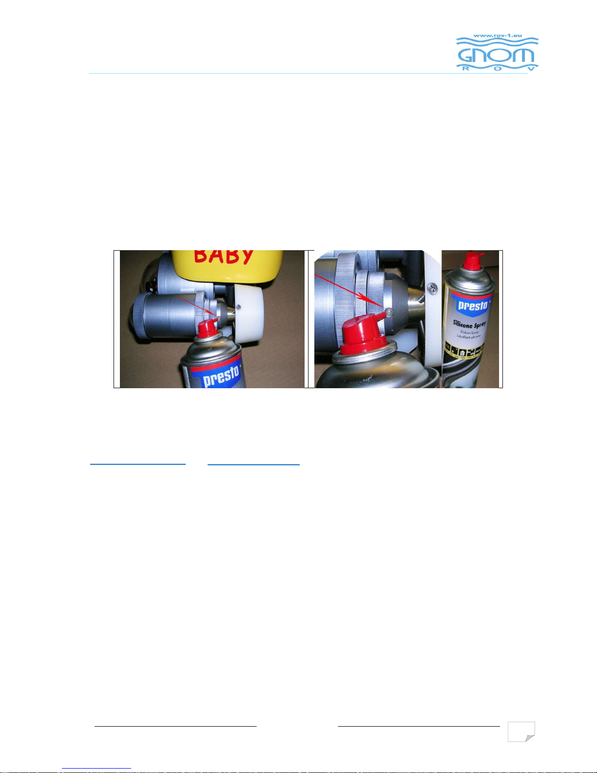
to check the magnetic disk coupling regularly
Use silicon oil spray for lubrication shafts of props every time after diving. Oil must
penetrate inside of conus heads of motors. See appendix position 96, 147, 217 of
thrusters assembly.
Avoid nods and twisting of cable.
Within the certificate of warranty the bond (joint) mainenance manual is included.
Use it only in case of emergency, if standard maintenance is insufficient.
Before this service consult technical problems in our company on email addresses:
odbyt@vftech.sk
or
vladoo@vftech.sk
Attention:
In case of non-professional action and damage of any part, the consecutive service in our
company will be charged.

v05/2016
18
7. SAFETY REQUIREMENT
1. Device belongs to CLASS 1 . For this reason the power adapter must have
connection to protective earth.
2. Swith-on and swith-off the machine by main 230V switch, which is placed over the
power cord to the external control unit.
3. Do not use the system with the damaged cable.
4. Do not touch underwater vehicle and the cable if you are in water and the power is
turned ON.
5. Keep the control module and the cable reel dry.
6. When recharging the battery disconnect the vehicle and the cable reel.

v05/2016
19
8. WARRANTY STATEMENT
VFTECH warrants that at the time of shipment all products shall be free from defects in material and
workmanship and suitable for the purpose specified in the product literature.
The unit/system warranty commences immediately from the date of customer acceptance and runs for a
period of 1 year ( except for thrusters ). Warranty for thrusters is to 6 months from the date of purchase.
Customer acceptance will always be deemed to have occurred within 72 hours of delivery.
Note: Any customer acceptance testing (if applicable) must be performed at either VFTECH premises or at
one of their approved distributors unless mutually agreed in writing prior to despatch.
Warranty service can only apply observance of inspection at intervals of 3 months from the receipt of the module.
When unrealized maintenance checks is not applicable warranty. You can apply warranty only in case if regular 3-
months service inspections of product are performed. In other case warranty can not be applied to product.
Conditions:
These include, but are not limited to, the following:
1. The warranty is only deemed to be valid if the equipment was sold through VFTECH or one of its approved
distributors.
2. The equipment must have been installed and commissioned in strict accordance with approved technical standards
and specifications and for the purpose that the system was designed.
3. The warranty is not transferable, except or as applies to Purchaser first then to client.
4. VFTECH must be notified immediately (in writing) of any suspected defect and if advised by VFTECH , the
equipment subject to the defect shall be returned by the customer to VFTECH , via a suitable mode of transportation
and shall be freight paid.
5. The warranty does not apply to defects that have been caused by failure to follow the recommended installation or
maintenance procedures. Or defects resulting from normal wear & tear, incorrect operation, fire, water ingress,
lightning damage or fluctuations in vehicles supply voltages, or from any other circumstances that may arise after
delivery that is without the control of VFTECH. (Note: The warranty does not apply in the event where a defect has
been caused by isolation incompatibilities.)
6. The warranty does not cover the transportation of personnel and per diem allowances relating to any repair or
replacement.
7. The warranty does not cover any direct, indirect, punitive, special consequential damages or any damages
whatsoever arising out of or connected with misuse of this product.
8. Any equipment or parts returned under warranty provisions will be returned to the customer freight prepaid by
VFTECH
9. The warranty shall become invalid if the customer attempts to repair or modify the equipment without appropriate
written authority being first received from VFTECH .
10. VFTECH retains the sole right to accept or reject any warranty claim.
11. Each product is carefully examined and checked before it is shipped. It should therefore
be visually and operationally checked as soon as it is received. If it is damaged in anyway, a
claim should be filed with the courier and VFTECH notified of the damage.
Note: VFTECH reserve the right to change specifications at any time without notice and without any obligation to
incorporate new features in instruments previously sold.
Note: If the instrument is not covered by warranty, or if it is determined that the fault is
caused by misuse, repair will be billed to the customer, and an estimate submitted for
customer approval before the commencement of repairs.
v05/2016
20
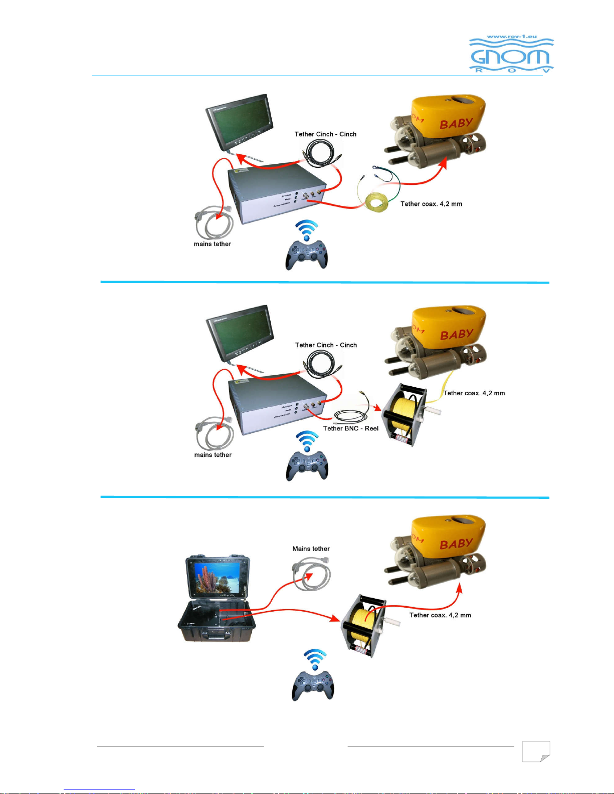
9. EXAMPLES OF LINKING MODULES

v05/2016
21
10. APPENDIX
5 PAGES
For use GNOM in fresh water you need install additional floatation [pos.1]
You should do the next:
1. To unscrew screws [pos.3] of skids [pos.2]
2. To remove skids [pos.2]
3. To install the additional block of floatation [pos.1] (enters into the equipment complete
set)
4. To install skids back

Power supply~230V,
50-60 Hz
power cable: max 20 m.
3G х 1.0 mm?
L, N, PE - wires
L, N, PE - wires
power cable: max 5 m.
3G х 0.75 mm?
plug
L
N
PE
L
N
F1
L
N
RF filter RCBO
TEST
~230V 50-60 Hz
Main board
+48V
Control
Video
F2
connection cable
Joystick
Power, video and control cable +48V
monitor
Hand
reel
RCBO - Residual Current Circuit Breaker
with Overcurrent Protection 16A/10iA
F1 - fuse 3A/250V
F2 - fuse 2A/250V
ROV
Tether, 50м.
Video out 1
Video out 2
Connection diagramm
+48V
AC\DC
additional monitor or
record device
Input power – max. 125W
wirelles

Сборочный чертеж малогабаритного подводного телеуправляемого осмотрового аппарата
Micro ROV assembly
Сборка корпуса Main hull assembly
1 Заглушка полозьев skid closing plug
2 Кольцо уплотнительное sealing ring
3 Полозья опорные skid
4 Крепление блистера blister fixing ring
5 Иллюминатор forward-viewing window
6 Корпус блистера front hull insertion
7 Корпус камеры camera fixing body
8
Кольцо крепления
PCB fixing ring
9
Сборка двигателя
horizontal thruster
10 Сборка задней крышки assembled closure backwall
11
Шпилька крепления
flotation fastering stud
12 Хомут крепления кабеля cable clip
13
Сборка двигателя
vertical thruster
14
Сборка двигателя
horizontal thruster
15 Болт screw
16 Крепление движителя thruster mounting
17 Шпилька stud
18 Плата электроники PCB
19 Крепление электроники PCB mounting
20
Кронштейн крепления
tilt camera fixing body
21 Болт screw
22 Кольцо уплотнительное sealing ring
23 Втулка опорных полозьев bush
24 Кольцо уплотнительное sealing ring
25 Гайка nut
26 Болт screw

Сборочный чертеж задней крышки
Backwall asembly
30 Болт screw
31 Шайба washer
32 Плата электроники PCB
33 Датчик глубины depth sensor
34 RS-разъем RS-connector
35 Крышка задняя backwall
36
Кольцо крепления задней
backwall mounting
37 Кольцо уплотнительное sealing ring
38
Крепление двигателя
thruster mounting
39 Кольцо уплотнительное sealing ring
40 Гермоввод cable pressure seal
41
Кольцо крепления
fit ring
42 Втулка гермоввода
cable pressure seal
43 Шайба washer
44 Болт screw
45 Гайка гермоввода кабеля
cable pressure seal
46 Хомут крепления кабеля cable clip
47 Кольцо уплотнительное sealing ring
48 Болт screw
50 Шайба washer

Сборка горизонтального
Horizontal thruster
55 Ограждение гребного винта propeller guard
56 Гайка крепления гребного
propeller cap nut
57 Гребной винт propeller
58 Кольцо крепления
propeller guard mounting
59 Втулка фильтра filter bushing
60 Оголовье thruster cone
61 Гайка крепления оголовья thruster cone n ut
62 Гайка корпуса thruster cap nut
63 Передняя часть корпуса thruster cap
64 Кольцо уплотнительное sealing ring
65 Шпилька thruster rod
66 Электродвигатель thruster
67 Шайба крепления двигателя motor mounting washer
68 Сегмент крепления
thruster mounting washer
69 Труба thruster tube
70 Кольцо уплотнительное sealing ring
71 Задняя часть корпуса thruster closure backwall
72 Кольцо уплотнительное sealing ring
73 Стекло осветителя light port
74 Прокладка sealing ring
75 Гайка задника closure backwall nut
76 Кольцо уплотнительное sealing ring
77 Проставка hull spacer
78 Гайка nut
79 Шайба washer
80 Винт screw
81 Муфта внутренняя inside magnetic coupling
82 Муфта наружняя outside magnetic coupling
83 Винт Screw
84 Втулка thruster bushing
85 Фильтр filter
86 Ось propeller shaft
Сборочный чертеж движителя
Horizontal thruster assembly

11. ANNEX
PROBLEMS SOLUTION
Alight LED on control
unit
Check that control unit is connected to a power supply
Check that control unit is switch on
If previous conditions are met but LED is still alight, check network fuse of control unit
Underwater unit does
not respond to JOYSTICK
Check that control unit is switch on – LED must illuminate
Check that joystick is switch on
Check batteries in joystick
Underwater unit does
not swim directly
Check horizontal thrusters – propellers have turn easy– check by finger
In case that some propeller turns hard, clean slide bearing of coupling axis of propeller
and check setting of coupling
Underwater unit does
not respond correctly to
Joystick
You have probably switch on function MAKRO on joystick ( some of models). Resolve
problem in according to the procedure in chapter JOYSTICK DESCRIPTION
The screen displays
incorrect value of
navigation depth
Make calibration of depth sensor in according to this manual
Underwater
module
does not respond to
joystick
Joystick is in sleep mode (power saving).
See chapter USER’S MANUAL FOR OPERATION

11. ANNEX
SERVICE COUPON
Coupon No.1
Date of sale
SERIAL NUMBER
DATE OF INSPECTION
TRUE
FALSE
DESCRIPTION OF REPARATION
HORIZONTAL THRUSTER L
HORIZONTAL THRUSTER R
VERTICAL THRUSTER F
VERTICAL THRUSTER B
LIGHTS
SERVO
COMPASS
DEPTH SENSOR
JOYSTICK
CONTROL UNIT
MOTOR COUPLING
STAMP AND SIGNATURE
Coupon N.2
Date of sale
SERIAL NUMBER
DATE OF INSPECTION
TRUE
FALSE
DESCRIPTION OF REPARATION
HORIZONTAL THRUSTER L
HORIZONTAL THRUSTER R
VERTICAL THRUSTER F
VERTICAL THRUSTER B
LIGHTS
SERVO
COMPASS
DEPTH SENSOR
JOYSTICK
CONTROL UNIT
MOTOR COUPLING
STAMP AND SIGNATURE
Coupon No.3
Date of sale
SERIAL NUMBER
DATE OF INSPECTION
TRUE
FALSE
DESCRIPTION OF REPARATION
HORIZONTAL THRUSTER L
HORIZONTAL THRUSTER R
VERTICAL THRUSTER F
VERTICAL THRUSTER B
LIGHTS
SERVO
COMPASS
DEPTH SENSOR
JOYSTICK
CONTROL UNIT
MOTOR COUPLING
STAMP AND SIGNATURE
Coupon No.4
Date of sale
SERIAL NUMBER
DATE OF INSPECTION
TRUE
FALSE
DESCRIPTION OF REPARATION
HORIZONTAL THRUSTER L
HORIZONTAL THRUSTER R
VERTICAL THRUSTER F
VERTICAL THRUSTER B
LIGHTS
SERVO
COMPASS
DEPTH SENSOR
JOYSTICK
CONTROL UNIT
MOTOR COUPLING
STAMP AND SIGNATURE

11. ANNEX
Year of purchase:
TABLE № 1. Registration of working time
Start and end date of
executed works
Place of works
Underwater unit working
time (hours)
Operator name and
signature

11. ANNEX
Table No. 2 Statistics of damaged and replaced fuses in control unit
Date / time of fuse
seasoning and her
replacements
Type and parameter
of network fuse
Type and parameter of
power cable fuse +180V
Operator name and work
position
Signature
1.
2.
3.
4.
5.
Table No. 3 Inspection of coaxial cable intact
Date Type of cable Result Name Signature
1.
2.
3.
4.
5.
Table No. 4 Inspection of grounding cable clamp resistance
Date Type of cable Result Name Signature
1.
2.
3.
4.
5.

11. ANNEX
Protocol of perform warranty repairs
Client
Address
Client’s agent name
Name of employee taking complaint
Date of taking complaint
Date of product sale
Type of product + serial number
Description of defect by client
Description of defect by service operator
Used material
Legitimate complaint Yes No
If no legitimate - reason
Date of repaired good expedition to client
 Loading...