

gneuss DMV 4000 Operating Instructions Manual
Page 1 of 15
Pressure Measurement Amplifier DMV 4000
Certified according to ISO 9001:2000
=
Operating instructions
Pressure Measurement Amplifier DMV 4000
=
=
Contents:
1. General description 6. Display and operating elements
2. Technical details 7. Programme access / barring
3. Assembly 8. Commissioning
4. Commissioning Electrical connections 9. Additional function
5. Adjustment Possibilities 10. Error Reading
Please refer to this instruction manual before connecting or operating the instrument
Update: August 2, 2011

Page 2 of 15
Pressure Measurement Amplifier DMV 4000
1. General Description:
The Gneuss pressure measurement amplifier type DMV 4000 is a measurement amplifier for pressure
transducers with strain gauge technology. Universal setting possibilities guarantee that all pressure
transducers with 1 to 4 mV output signal can be connected. Furthermore, three freely-adjustable limit
contacts and one optional analogue signal 0-10 V, 0-20 mA or 4-20 mA can be processed. A peak
hold function, simple operation via a touch sensitive keypad and extreme sturdiness guarantees a high
ease of operation. The unit can be protected against unauthorized use via possible software settings.
2. Technical specifications:
Dimensions: 96 mm x 48 mm (1/8 DIN front housing) x 110 mm
Incl. Terminal block with quick-lock function by means of plastic clamps, for
wall thicknesses of up to 10 mm.
Colour: Dark grey
Weight: approx. 250 g
Panel cut- out size: 92,0
+0,8
x 45,0
+0,6
IP rating: From front IP 65, connection IP 00
Input: Wheatstone resistance bridge 350 Ω....10 KΩ
Supply voltage: 5 VDC transducer supply
Sensitivity: 1 mV/V….4mV/V
Relay Contacts: Up to 3, over the overall measuring span freely adjustable relays
Switching capacity: 250 VAC = 2A / 120 VAC = 4A
Fail –Safe feature: Performance control – Sensor connections
Accuracy: +/- 0,1 % of measuring value, +/- 1Digit
Ambient temperature influence <0.1 %/20 °C
Power supply: Supply voltage 100…230 VAC +/- 10 %, 50 - 60 Hz.
Power consumption approx. 4 W (optional 24 V DC)
Display: 5-digit seven segment LEDs, 15 mm high, luminous: green or
red when exceeding a preset alarm parameter, indicating range
-99999….99999, arithmetic overflow is indicated by 5 cross-ledgers
Connection of the
Instrument: On the reverse via a 36-pole terminal block
Ambient conditions: Operating temperature 0-50 °C / humidity level 5….95 % (no condensation)
Analogue output: 0-20 mA or 4-20 mA at current load 750 Ω /15 V max.
0-10 V at 500 Ω resistance at 0-20 mA set parameter

Page 3 of 15
Pressure Measurement Amplifier DMV 4000
3. Assembly:
The instrument is designed for panel assembly. It is to be assembled in such a manner, as to protect it
from humidity, dirt and vibration. The ambient temperature is not to exceed 50 °C.
4. Commissioning electrical connection:
The instrument is only to be connected and operated by qualified personnel. Please see attached
diagram for wiring connections. The local regulations for operating electrical factory equipment are to
be stringently adhered to.
CE-Mark
For unrestricted operation of the instrument according to the guidelines of the electromagnetic
compatibility 89/336/EEC all analogue wiring needs to be shielded. The shield is to be one sided
UL recommendation: 1) Use copper conductors designed for temperatures up to 60/70 °C
2) Minimum cross-section of 1mm² to be utilized. (AWG 18)
Analogue output:
For an analogue output of 0-10 V, the pre-installed 500Ω resistance is to be used with a set parameter
of 0-20 mA. For all other outputs, the pre-installed 500Ω resistance has to be removed from terminals
19 / 20.
=
=
=
=
=
=
=
=
=
=
=
Page 4 of 15
Pressure Measurement Amplifier DMV 4000
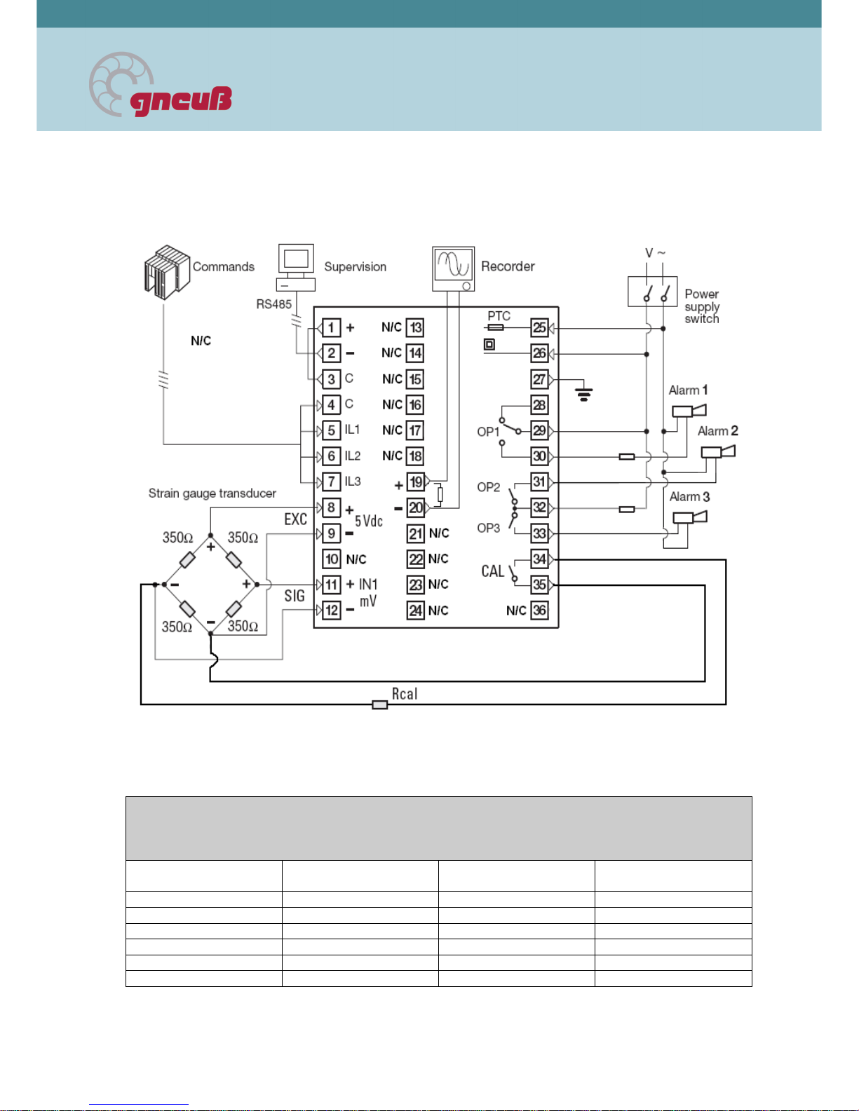
Wiring configuration:
=
=
=
=
=
=
=
Colour coding and termination of Gneuß extension cable
Pressure sensor
Pin
Colour
(6P)
Function DMV 4000
terminal
A Yellow Signal + 11
B White Signal - 12
C Brown Supply + 8
D Green Supply - 9
E Pink Cal. 80 % 34
F Grey Cal. 80 % 35
=
Page 5 of 15
Pressure Measurement Amplifier DMV 4000
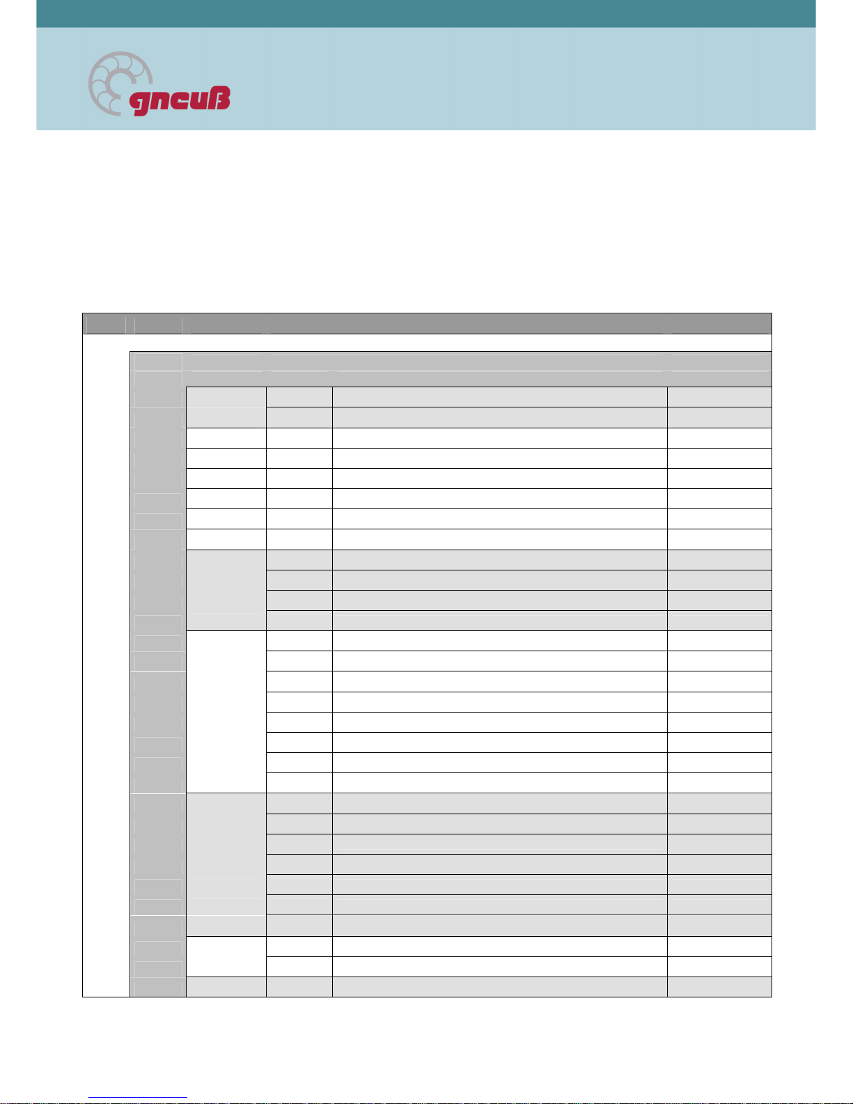
5. Adjustment possibilities:
The following table lists the possibilities of parameter changes
=
conf
confconf
conf
Configuration menu
pass
passpass
pass
Code I Configuration menu password Input Range
base.c
base.cbase.c
base.c
FREQ
FREQFREQ
FREQ
Frequency of input voltage 50 / 60
INP
INPINP
INP
UNiT
UNiTUNiT
UNiT
Engineering units Bar / PSI / Mpa
DP
DPDP
DP
Number of decimals 0...3
FILT
FILTFILT
FILT
IN 1 filter constant time 0...30 s
RAN.Lo
RAN.LoRAN.Lo
RAN.Lo
Low range -9999...99999
RAN.Hi
RAN.HiRAN.Hi
RAN.Hi
High range -9999...99999
A0
A0A0
A0
AO.tYP
AO.tYPAO.tYP
AO.tYP
Analogue Out Type
0-20 / 4-20
AO.Lo
AO.LoAO.Lo
AO.Lo
Analogue Out Low Range -9999...99999
AO.Hi
AO.HiAO.Hi
AO.Hi
Analogue Out High Range -9999...99999
sys
syssys
sys
Prot
ProtProt
Prot
Communications protocol Modbus / Jbus
baUd
baUdbaUd
baUd
Baud rate 200...57600
ParY
ParYParY
ParY
Parity none/euen/odd
Addr
AddrAddr
Addr
Communications address 1...247
CodeI
CodeICodeI
CodeI
Password 1 0...65534
Co
CoCo
Code2
de2de2
de2
Password 2 0...65534
Code3
Code3Code3
Code3
Password 3 0...65534
ALARM
ALARMALARM
ALARM
AL!.LT
AL!.LTAL!.LT
AL!.LT
Reset by acknowledgement or external (IL1) none / Ltch
AL2.LT
AL2.LTAL2.LT
AL2.LT
Reset by acknowledgement or external (IL2)
none / Ltch
AL3.LT
AL3.LTAL3.LT
AL3.LT
Reset by acknowledgement or external (IL3)
none / Ltch
0VT 1
0VT 10VT 1
0VT 1
Output action of alarm 1 direct / reverse
0VT 2
0VT 20VT 2
0VT 2
Output action of alarm 2 direct / reverse
0VT 3
0VT 30VT 3
0VT 3
Output action of alarm 3 direct / reverse
(AL
(AL(AL
(AL
CAL.PT
CAL.PTCAL.PT
CAL.PT
Shunt for strain gage cal. 50...100%
Ehit
EhitEhit
Ehit
Exit Configuration menu
 Loading...