

GNE Honeybee350, Honeybee700, Honeybee800, Scouter450, Swarm Installation & User Manual
...Page 1
GNE module level optimization and monitoring system
Installation User Manual
(Honeybee350/400, Honeybee700/800, Scouter450,Swarm, Beehive)
Jiangsu GNE New Energy Technology Co., Ltd.
Tel:+86 519 8728 1798
Email: service@gnetek.com | Web:www.gnetek.com
Add.: 1F/B, No.218 Hongkou Road, Liyang City, Jiangsu 213300, CHINA
Page 2

Notice
u This user manual is used to install and maintain GNE
power optimizer models Honeybee 350/400, Honeybee
700/800, PV monitor model Scouter350/450 and data
processing devices.
u No permission to disassemble and repair the products
to ensure the safety of personnel. For services, please
look for trained or qualified professionals.
u Before installing and using the power optimizers,
please familiarize yourself with all the tips and warnings
on the products, as well as the safety instructions and
other applicable safety guidelines in the inver ter
manual and the PV module installation instructions.
u To reduce the risk of fire and electric shock, install the
power optimizers in strict acco rda nce with loca l
electrical standards and codes.
u Before installing the optimization and monitoring
products, please remove all metal accessories that you
wear to reduce the risk of touching live circuits. It is
strictly forbidden to install and debug in bad weather.
u Do not operate if the GNE products can be physically
damaged. Check existing cables and connectors to
ensure they are in good condition and status. Do not
operate the cables and connectors of GNE products if
they are damaged or unqualified.
u Do n o t c o nnec t or d isc o n nec t th e GNE powe r
optimizers and montoring products under load. There
is also a risk of electric shock when shutting down the
inverter or the GNE products. After disconnecting all
power supplies, the capacitor inside the inverter can
continue to charge for a few minutes. Before measuring
the line, first measure the voltage at the inverter and
confirm that the capacitor is no longer charged.
u I n s t a l la tion must be perf o r m e d b y a t r a i n e d
professional. GNE is not liable for any loss or damage
caused by improper operation, discomfort or misuse of
these products.
u Before the GNE customer service personnel provide
services, please make sure that the data aggregation
device Beehive is powered on and the internet is fine,
and optimizers work in power-on status, then check the
current, voltage and power of the PV series.
Page 3
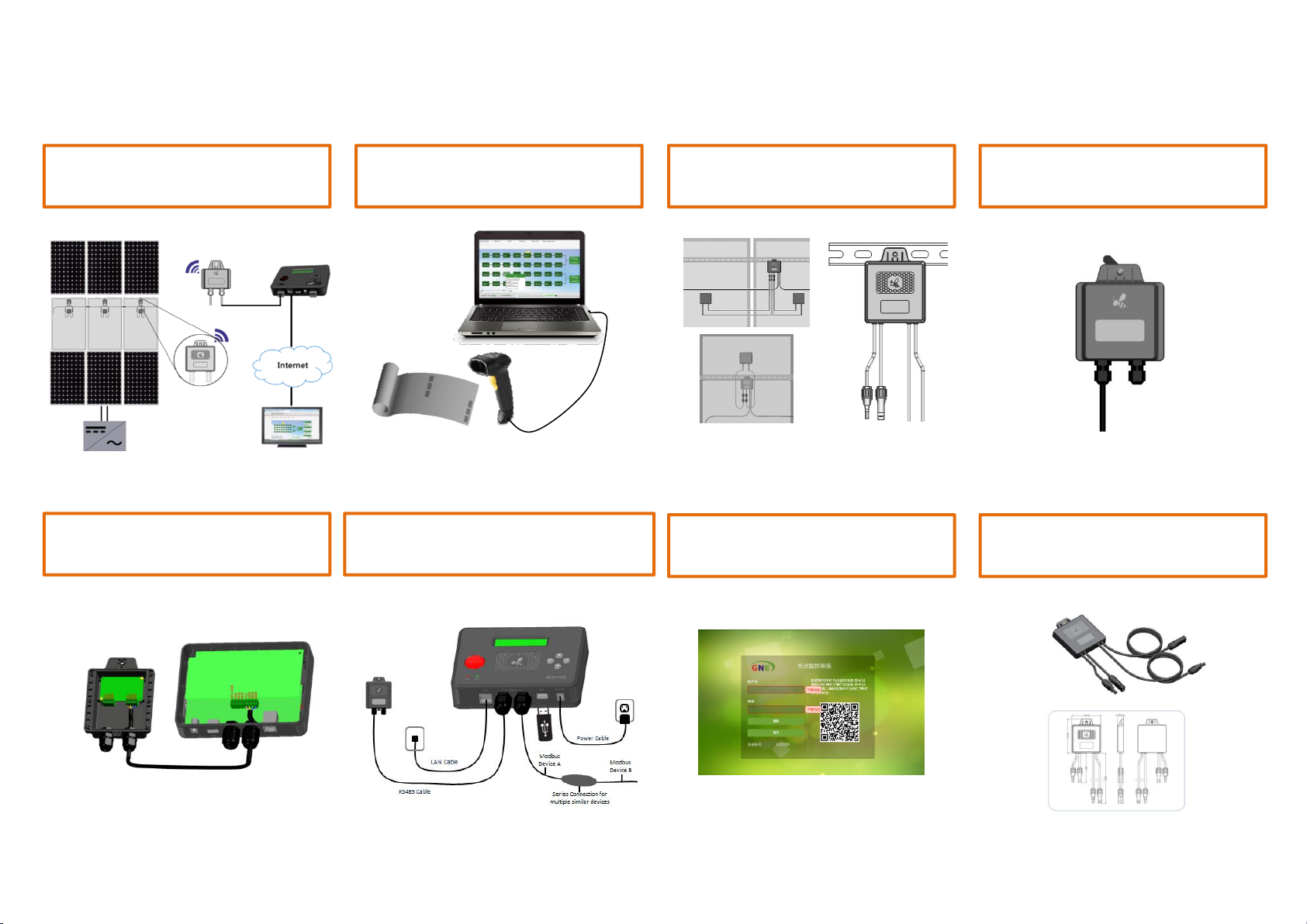
Installation Steps:
1. Smart PV diagram (Apidae)
5. Connection to Swarm
and Beehive
2. Register MACID of GNE
models
6. Installation of data aggregation
device (Beehive)
3. Installation of optimizers
or PV monitors
7. Setup in data cloud center
(Honeypot)
4. Installation of data
acquisitoin unit (Swarm)
8. Appendix - Product
Specification
For more information, please visit GNE website www.gnetek.com, or contact us (email: service@gnetek.com, telephone: +86 519 87281798)
Page 4
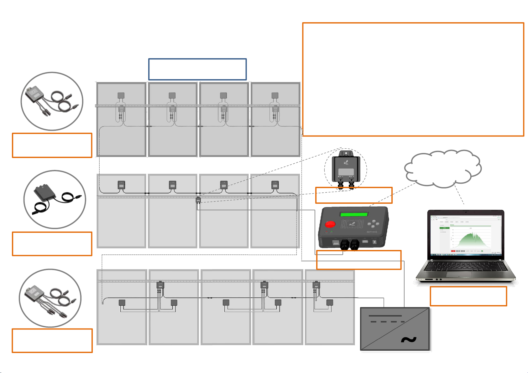
1. Smart PV Diagram(Apidae)
PV Array
Honeybee350/400
Scouter450
Connection Description:
• One Beehive can communicate up to 5 Swarms by 485 cable and
gather the generation data of 2000 optimizers and monitors
• One Swarm can wirelessly communicate 400 optimizers
• Honeybee350/400: Sole module power optimizer to connect one
PV panel
• Honeybee700/800: Dual module power to connect Two PV panels
• Scouter450: Sole module monitor to connect one PV panel
Internet
Data Acquisition Unit
Swarm
Integrated Optimizer
Smartbee350
Honeybee700/800
Data Aggregation Device
Beehive
Data Cloud Center
Honeypot
Inverter
Page 5

2. Register MACID of GNE models
①. Plan the installation location of each
power optimizer or PV module
monitor
②. Take the power optimizer or PV module
monitor and write down the 8-digit MACID
number on the pl ant map, or string li st, or
construction drawing. And write down the 8-digit
MACID number of Swarm and Beehive.
A1
A2
B1
A3
B2
A4
B3
A5
B4
A6
B5
A7
B6
A8
B7
A9
B8
A10
B9
B10
Inverter
③. The i nstall at io n posit io n of th e powe r
optimizers or the PV module monitors should
accord to the previously recorded MACID order.
Page 6

3. Installation of optimizers or PV monitors
Ø Precautions before installation
PV Module PV Module PV Module PV Module
Description: When all the inputs of the
optimizers are connected to the output
①
Correct operation: Connect the optimizer's outputs in the
same direction
Wrong operation: simultaneous connection of the optimizers'
outputs in both directions.
PV Module PV Module PV Module PV Module
of the PV junction boxes, the outputs
of the o ptimizers are connected in
series.
Correct operation: Connect the outputs
of the optimizers in the same direction
to ensure that the last two ends of the
string are the positive and negative
two-pole interfaces, not the same-pole
interface (as shown in Figure 2).
②
Negative interface
Inverter
Positive interfaceNegative interface
Page 7

3. Installation of optimizers or PV monitors
①. Record the product MACID numbers of the optimizers
or PV monitor on the system form or power station map
or construction drawing to establish a power station in
cludy center for tracking the operation status of each
panel even the whole PV station.
②. Use a screw or cable tie to position the optimizer or
PV monitor one by one according to the registered
MACID number position, and fix it on the bracket or panel
frame. If the bracket has no mounting holes, it can be
drilled and mounted with a hole size of 6mm.
③. The shorter pair of cables of the power optimizer or
the PV monitor are the input terminals, and the longer
pair of cables are the output terminals for the power
optimizer or the PV monitor to be connected in series and
finally connected to the inver or the combiner box.
Cabling sequence: firstly connect all the input cables of
the optimizers to the output cables of the PV junction box,
then connect the output cables of all the optimizers in
series (please refer to the previous page for notes)
Remarks:
W h e n c o n n e c t i n g t h e d u a l m o d u l e o p t i m i z e r
Honeybee700/800 to one PV panel, one pair of the
input cables of the optimizer are connected the
output ends of the PV module, and the other pair is
directly docked.
Page 8

4. Installation of data acquisitoin unit (Swarm)
Swarm
Cascade
Swarm
RS485
Terminal
RS485
Terminal
485B
485B
485A
485A
GND
GND
12V12V
①. Swarm is mounted on the bracket at
the center of the PV module array and
can be fixed with cable tie or a screw of
diameter 6mm.
50m
②. If yo u n eed to con n ect mor e
Swarms, please connect th em with
RS485 cable.
Note:
The data transmission between the
Swarm and the power optimizers is
wireless, and the effective
communication distance is 50 meters.
Swarm cascade table:
RS485
Connect
next Swarm
RS485
Connect Beehive or
the Swarm in the front
Page 9

5. Connection to Swarm and Beehive
Swarm
Cascade
Swarm Beehive
A third
device
RS485
Terminal
RS485
Terminal
RS485
Terminal 1
RS485
Terminal 2
RS485
Terminal
485B
485B485B
485B
485B
485A
485A
485A
485A
485A
GND
GNDGND
GND
GND
12V
12VVCC
VCC-USER
The wiring connection table of Swarm and Beehive
① Determine where the Beehive is installed
② Open the back covers of the Beehive to the
③ Connect the 485 cable to the RS485 port
and the length of RS485 cable from the
Beehive to the Swarm
Swarm
numbered 1 on the Beehive (refer to the
right table for the wiring connection table)
and tighten it with a flat head screwdriver.
④ Connect the other end of the 485 cable to
any one RS485 interface of the Swarm, and
the wiring order of the four color wires of
the RS485 in the Swarm and the Beehive are
c o n s i s t e n t . N o t e : A n y e r r o r i n t h e
connection order would cause damage to
the Swarm or the Beehive.
⑤ Tighten the screws on the back cover of the
Sw a r m and t he B e e h ive w i t h a cr o s s
screwdriver.
Page 10

6. Installation of data aggregation device (Beehive)
Notes for Operation:
1. The protection grade of the Beehive is IP20 and needs to be installed indoors. If it
needs to be installed outdoors, please add a waterproof box.
2. Connect power, ethernet cable or third-party device to the corresponding terminals.
3. Test whether the Swarm and the network cable work normally (select“FIND 485”in
the menu of the Beehive, press “OK”, then the connection number of the 485
devices will be displayed)
Ethernet cable
RS485 cable
Modbus
Device A
A third-part device
100~240V
Power cord
Modbus
Device B
Page 11

7. Setup in data cloud center (Honeypot)
Log in the GNE homepage: http://gne.gnetek.com,
click on the monitoring center in the upper right corner
② Fill in the information of the new account
① New Account Register
Select language
New account Register
Page 12

7. Setup in data cloud center (Honeypot)
③ Fill in the information of the
inverter and the panel
⑤ Select optimizer model, fill in 8 digits of MACID of the optimizers
Add more inverters
or panels if needed
④ Fill in the 8-digit of MACID of the Beehive
Page 13

7. Setup in data cloud center (Honeypot)
⑥ Adjust the location of the optimizers per the physical layout of the PV station
Page 14

SPECIFICATION
MODEL
Honeybee350
Honeybee700
Honeybee400
Honeybee800
Scouter450
INPUT
Max. Input Power
350 W
350*2 W
450 W
450*2 W
450W
Max. Input Voltage
60 Vdc
75 Vdc
75 Vdc
Min.Module MPPT Voltage
16 Vdc
12 Vdc
-
Max. Input Current
10 Adc
13 Adc
13 Adc
Short Circuit Current
15 Adc
OUTPUT
Output Power Range
0~350 W
0~350*2 W
0~450 W
0~450*2 W
0~450W
Max Output Current
11 Adc
13 Adc
13 Adc
Output Voltage Range
0 ~ Voc
Max System Voltage
1000 Vdc
1500 Vdc
1500 Vdc
EFFICIENCY
Max. Converter Efficiency
99.50%
99.60%
99.60%
99.60%
99.90%
INSTALLATION
SPECIFICATION
Size (L*W*T, mm)
127.5*106*22
130.5*129*25
130.3*109.6*25
130*132*24.5
127.5x106x22
Weight
530 g
810 g
588 g
765 g
400g
Input Linker
MC4
MC4
MC4
Output Linker
MC4
MC4
MC4
Working Temperature
-40 ~ +85 ℃
Inbreaking Protection
IP65
IP67
IP67
Relative Humidity
0~100%
STANDARD
COMPLIANCE
EMC
7IEC61000-6-2, IEC61000-6-37
Safety Regulations
IEC62109-1 (Class II safety)
Overvoltage Category
III
Certificate
CQC/TUV/CSA
CE
-
Appendix - Product Specification
 Loading...