

GNE 1578172GN, 1578182GN, 1578202GN, 1577543GN, 1577544GN Assembly And Operating Instructions Manual
Page 1
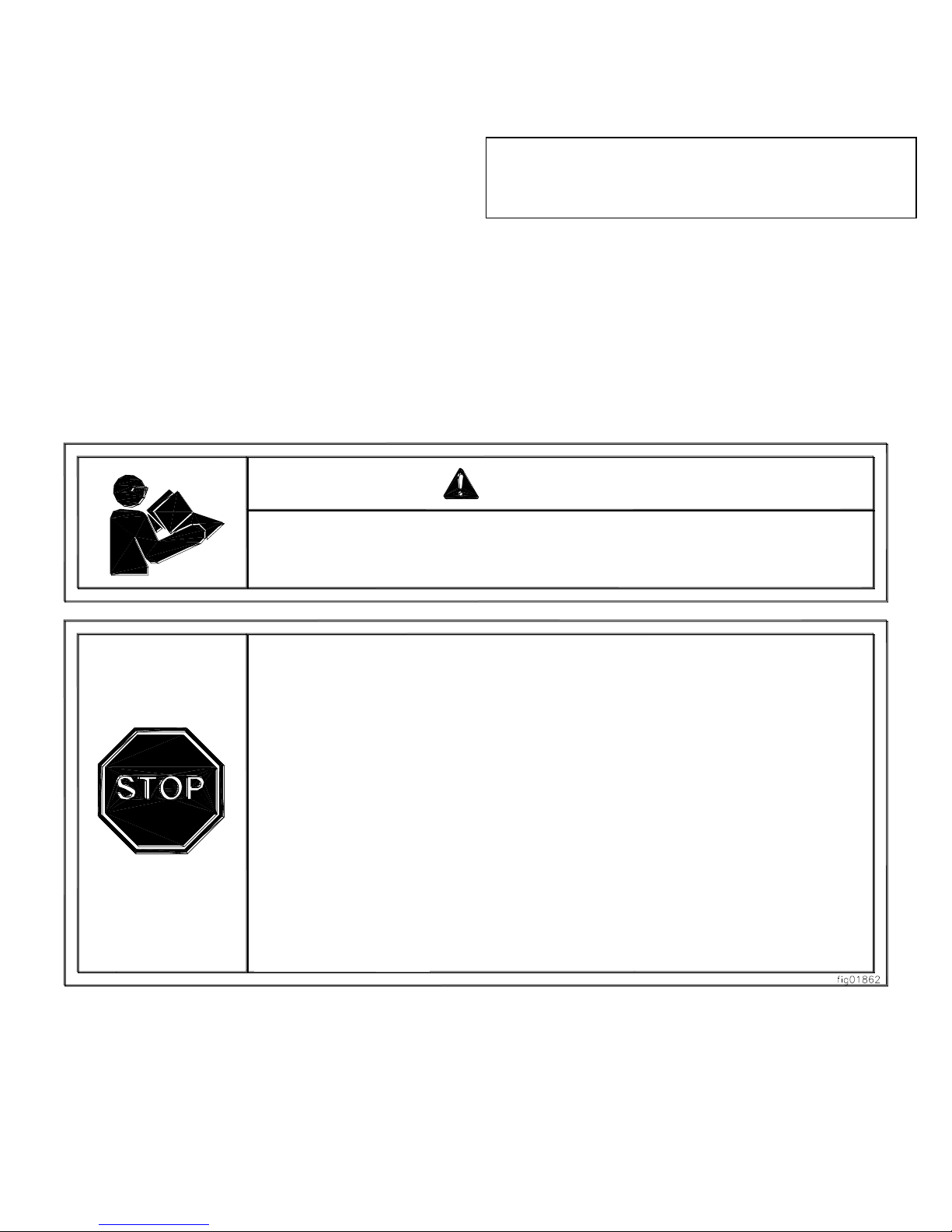
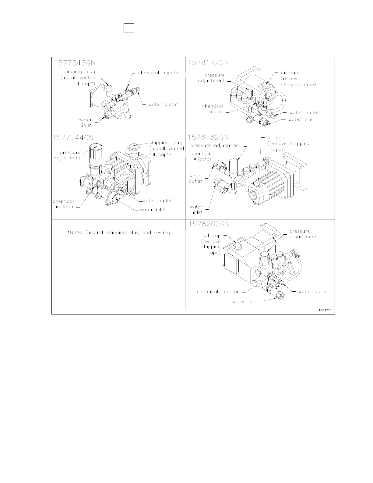
Engine is shipped without oil.
- Before starting engine, fill engine oil.
- See engine manual for engine oil requirements.
Pump is shipped with oil.
- Remove shipping plug and install vented fill cap. (Comet Pumps)
- Remove shipping tape from pump oil fill cap. (Cat Pumps)
- See pump oil cap section of this manual.
Closely inspect all components.
-If you have damaged components then: Contact the freight company that
delivered the unit and file a claim.
-If you have missing components then: Contact Customer Service at
Read this manual.
Serious injury or death can result if safety instructions are not followed.
WARNING
ITEM NUMBERS: 1578172GN, 1578182GN,
1578202GN, 1577543GN,
1577544GN
1-800-822-0295
M1578112GNC
Owner’s Manual
Pressure Washer: Machine that cleans dirty
surfaces with high pressure water.
Any Questions, Comments, Problems or Parts Orders
Call GNE Product Support 1-800-822-0295
Page 2
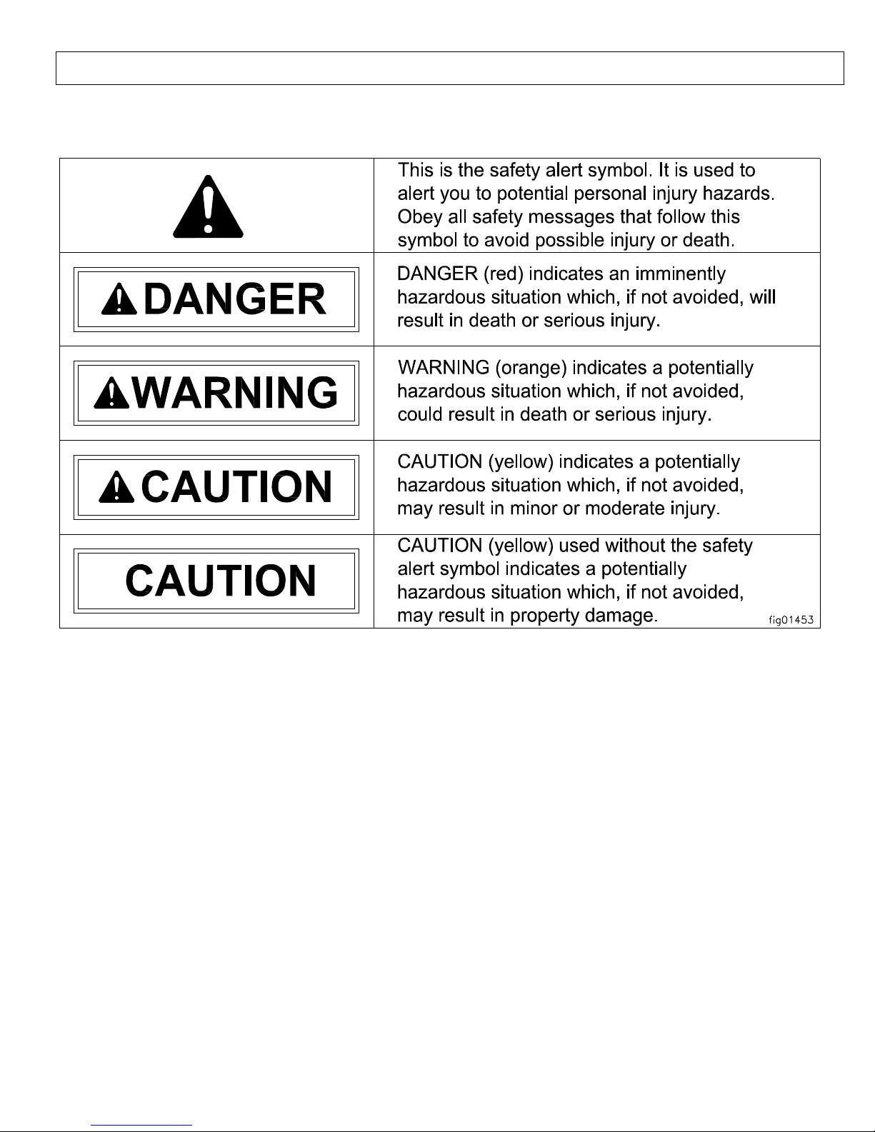
Hazard Signal Word Definitions
2
Page 3

Table of Contents
3
Important Safety Rules ......................................….
4
Warning Label Locations ...................................….
6
Assembly Instructions…………………………………...
7
Machine Component Identification…………………….
10
Pump Oil Cap and Pump Component Identification…
11
Operation Instructions ........................................…
12
Water Supply……………….…………………………….
12
Start-Up/Shut-Down Instructions……………………….
13
Spray Gun Safety Lock and Attaching the Lance…….
14
Installing Nozzles and Quick Connect hoses…………
15
Applying Chemicals..…………………………………….
16
Maintenance and Storage..................................….
17
Maintenance Mode and Maintenance Schedule….
17
Pump Oil Change….…………………………………
18
Long Term Storage…………………………………..
19
Winter Storage………………………………………..
19
Troubleshooting ...................................……...........….
20
Specifications .....................….................................…
21
Parts Exploded View ..................................................
22
Pump Exploded Views…………………………………..
24
Pump Breakdowns………………………………………
26
Warranty
33
Page 4
Important Safety Rules
4
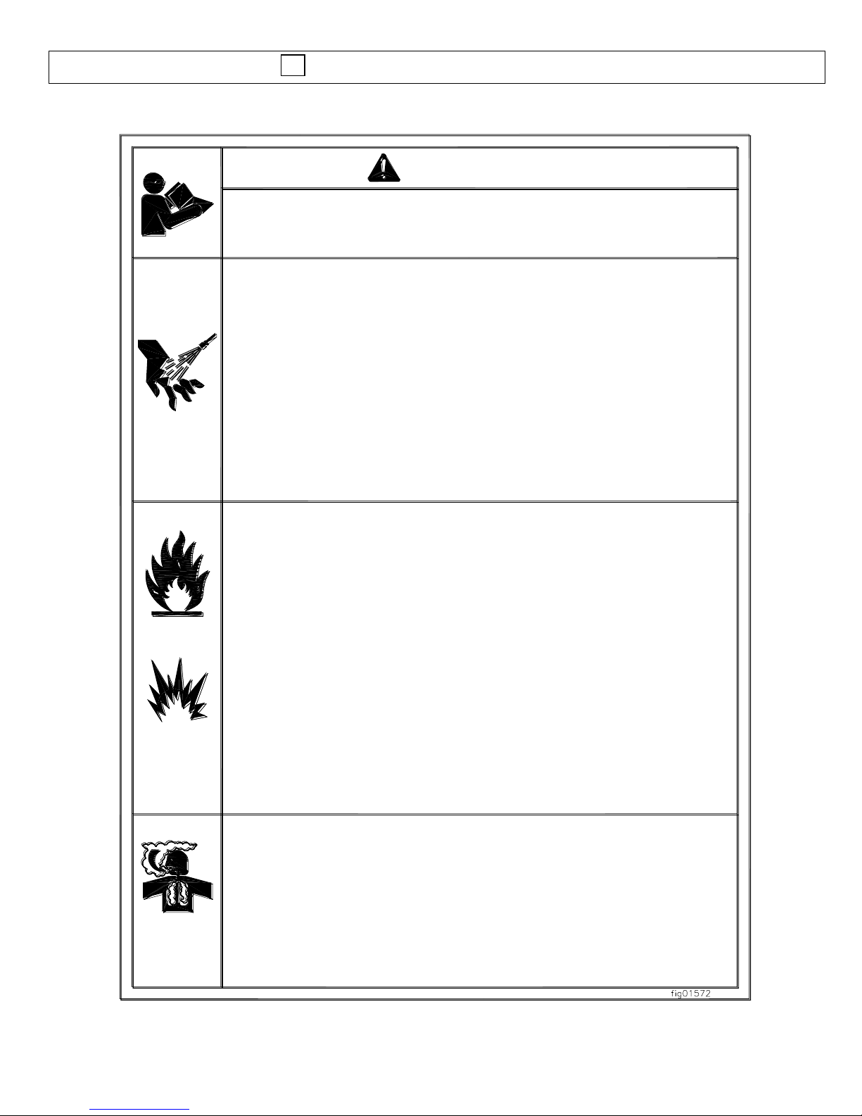
1.) Read owner's manual completely.
Serious injury or death can result if safety instructions are not followed. You must be
16 or older to operate this machine. Keep untrained people away.
2.) Skin puncture hazard.
High pressure fluid can inject under skin resulting in serious injury including
amputation. Do not direct spray at people or animals.
-If skin injection happens, seek IMMEDIATE surgical treatment.
-Do not check for leaks with hand. Instead, use a piece of cardboard to check for
leaks.
-Do not use unit if exterior hose damage is evident. Make sure all fittings are tight
before starting. Relieve system pressure before servicing.
-Know how to stop engine and bleed pressures quickly. Be thoroughly familiar with
the controls.
-Make sure accessories meet the unit's temperature and pressure limits.
-Stop engine, bleed pressure, and engage spray gun safety lock before leaving unit
unattended.
3.) Risk of fire and explosion.
Hot exhaust fumes from engine can cause fire. Gasoline is highly flammable and
explosive. You can be burned or seriously injured when handling fuel.
-Position muffler at least 7 feet from combustible objects.
-Before adding fuel, stop the engine and keep heat, sparks, and flame away. Do not
add fuel when engine is running or still hot. No smoking near engine.
-Do not pump fuel directly into engine at gas station. Static charge can build and
ignite fuel. Use a UL approved fuel container to transfer gas to the engine. Wipe up
fuel spills immediately.
-Only store and handle fuel outdoors. Gasoline vapors can ignite if they collect
inside an enclosure. Explosion can result.
-Do not change or add to exhaust system. Fire can result.
-Do not change or add fuel tanks or fuel lines. Fire can result.
-Before each use, check fuel tank and fuel lines for leaks. Any fuel leak is a fire
hazard. Fix any fuel leaks before starting engine.
-During transportation take precautions to make sure pressure washer will not tip
over and cause a fuel leak fire hazard.
4.) Poisonous gas.
This machine gives off carbon monoxide, a poisonous gas that can kill you. You
CANNOT smell it, see it, or taste it.
-ONLY run machine outdoors and away from air intakes.
-NEVER run machine inside homes, garages, sheds, or other semi-enclosed spaces.
These spaces can trap poisonous gases, EVEN IF you run a fan or open doors and
windows.
If you start to feel sick, dizzy, or weak while using this machine, shut it off and get to
fresh air RIGHT AWAY. See a doctor. You may have carbon monoxide poisoning.
WARNING
Save These Instructions
Page 5
Important Safety Rules
5
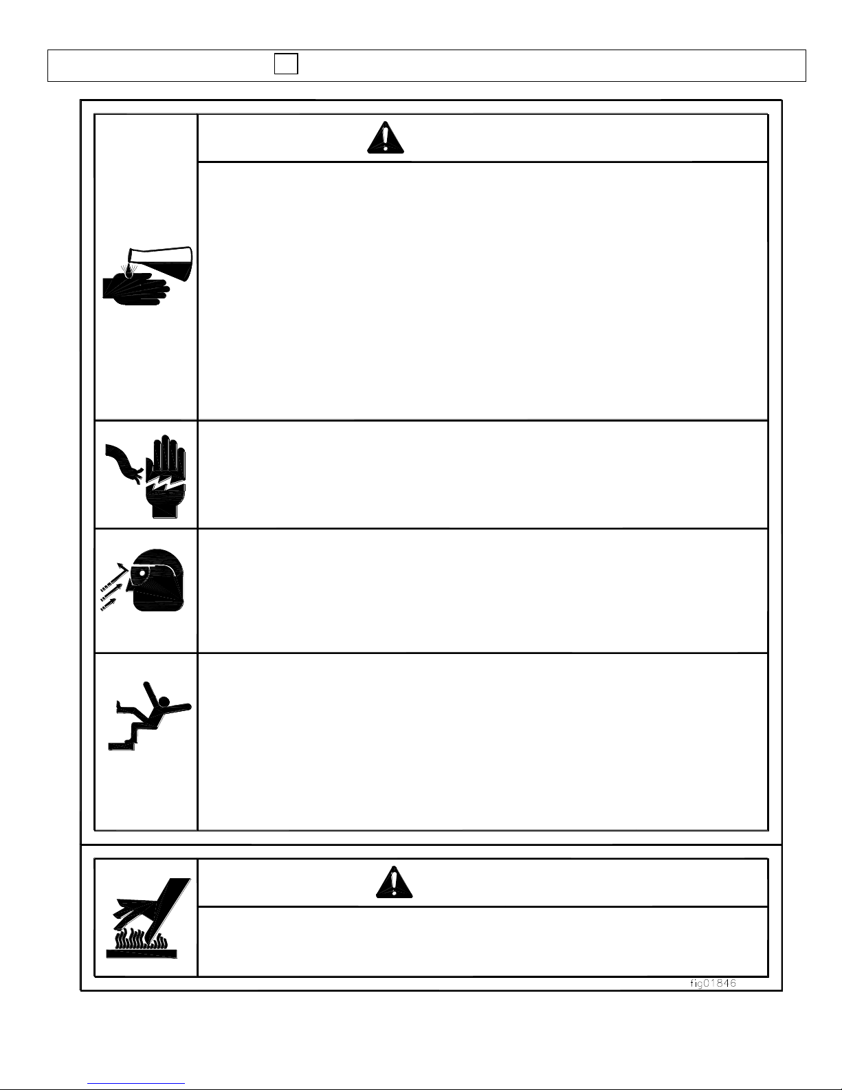
5.) Risk of exposure to dangerous chemicals.
Serious injury or death can result if chemical manufacturer instructions are not
followed.
-Wear protective gloves when handling and cleaning with chemicals.
-Understand all safety hazards and first aid for all chemicals being used.
-When cleaning filters, check if chemicals have been used and take any
precautions that are recommended by the chemical manufacturer.
-Different chemicals may interact dangerously with each other, always follow
chemical manufacturer directions before switching chemicals.
-Calculate the correct amount of chemical to mix, dispose of excess chemical
per the manufacturer instructions.
-Never spray flammable liquids.
6.) Risk of electrocution.
Electricity can kill you. Keep water away from electrical outlets and electrical
devices.
7.) Flying objects.
Small particles may fly out while spraying. Wear safety glasses. Serious eye
injury can occur.
Make sure nozzle is secure before squeezing trigger. If nozzle is not secure it
will become a projectile.
8.) Fall hazard.
Pressure washer creates puddles and slippery surfaces. Keep good footing
and balance. Serious injury can occur.
-Wear footwear cabable of maintaining a good grip on wet surfaces.
-Gun kicks back. Hold with both hands.
-Do not overreach or stand on unstable supports.
-Do not stand on ladders or scaffolding.
-Do not place pressure washer on soft or unstable ground.
CAUTION
1.) Hot muffler.
You can be burned by muffler. Do not touch.
WARNING
Page 6
6
SHUT-DOWN INSTRUCTIONS
1. Turn engine OFF.
2. Turn water supply OFF.
3. Squeeze trigger to
relieve system pressure.
4. Remove garden hose.
5. Remove pressure hose.
6. Turn fuel valve OFF
(if equipped).
START-UP INSTRUCTIONS
1. Attach garden hose.
2. Attach pressure hose.
3. Attach gun and lance.
4. Turn water supply ON.
5. Squeeze trigger to
purge air from pump.
6. Insert nozzle.
7. Start engine.
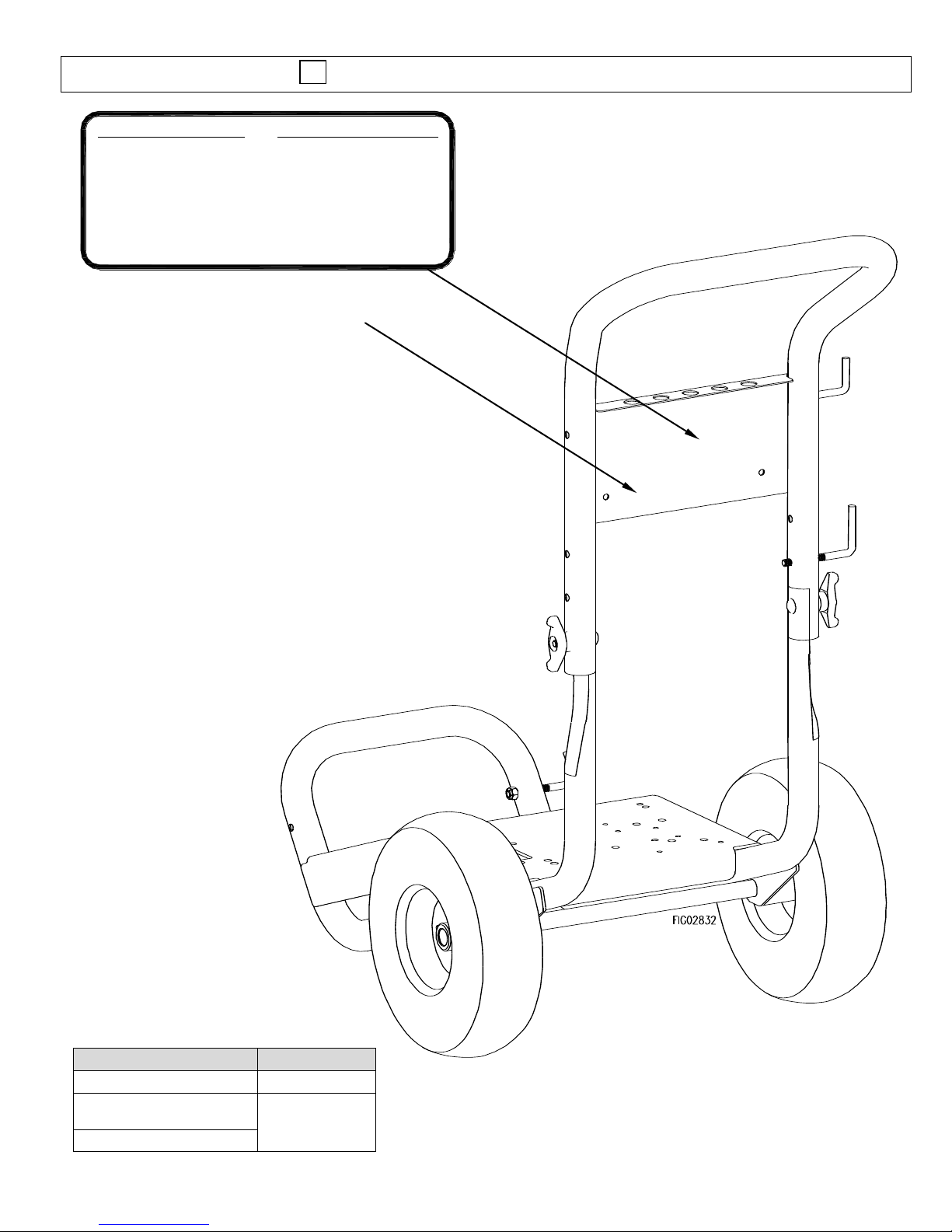
Call 1-800-822-0295 to order new labels.
Description
Item#
Instruction Label
781027
Burn Hazard-
Refer to breakdown (ref #23)
781026
Warning
*Located on Engine*
Warning Label Locations
Page 7
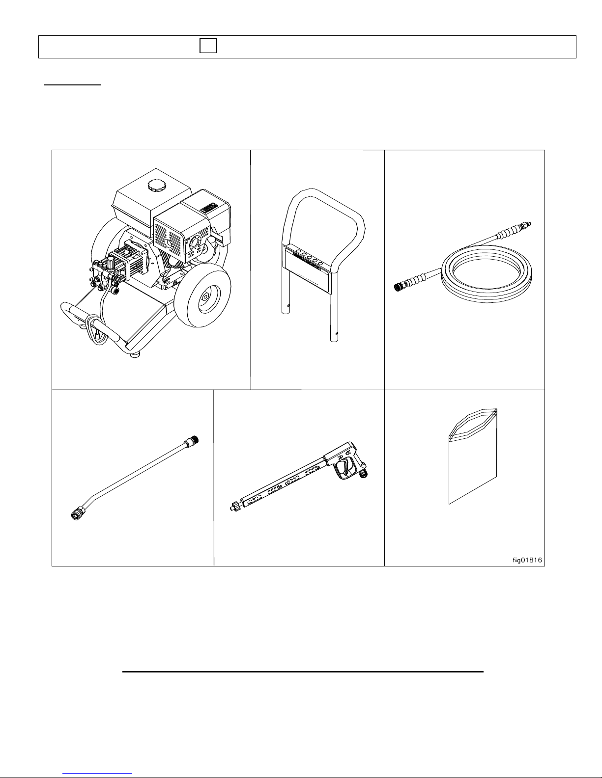
Assembly Instructions
7
Pressure Hose
Hardware Bag
Spray Gun
Handle
Engine/Pump/Base Assembly
Lance
I.) Unpack
Your pressure washer is shipped in two boxes except for models 1577543 and 1577544 which are
shipped in one box. Separate and identify the components found in the box/boxes.
* Depending in model, components may appear differently than illustrated
Any Questions, Comments, Problems or Parts Orders
Call GNE Product Support 1-800-822-0295
Page 8
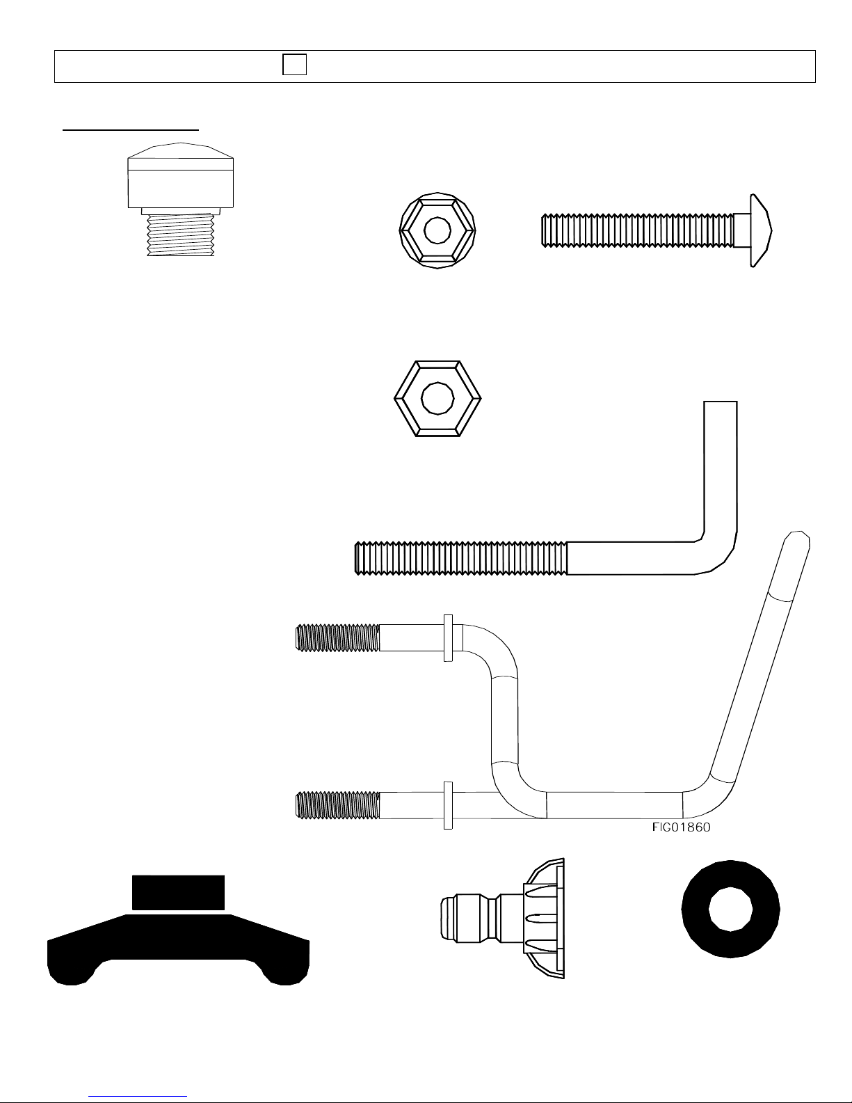
8
Hose Hook – Qty 1
Part # 779761
Flange Nut – Qty 2
Part # 82019
Carriage Bolt – Qty 2
Part # 82233
Vented fill cap
1577543GN,1577544GN
Gun Hook – Qty 1
Part # 38509
T- Handle Knob – Qty 2
Part # 38578
Nozzle – Qty 2 or 5
Varies by model
Grommet – Qty 5
Part # 35198
Nylock Nut – Qty 2
Part # 777495
II.) Hardware Bag
Assembly Instructions
Page 9
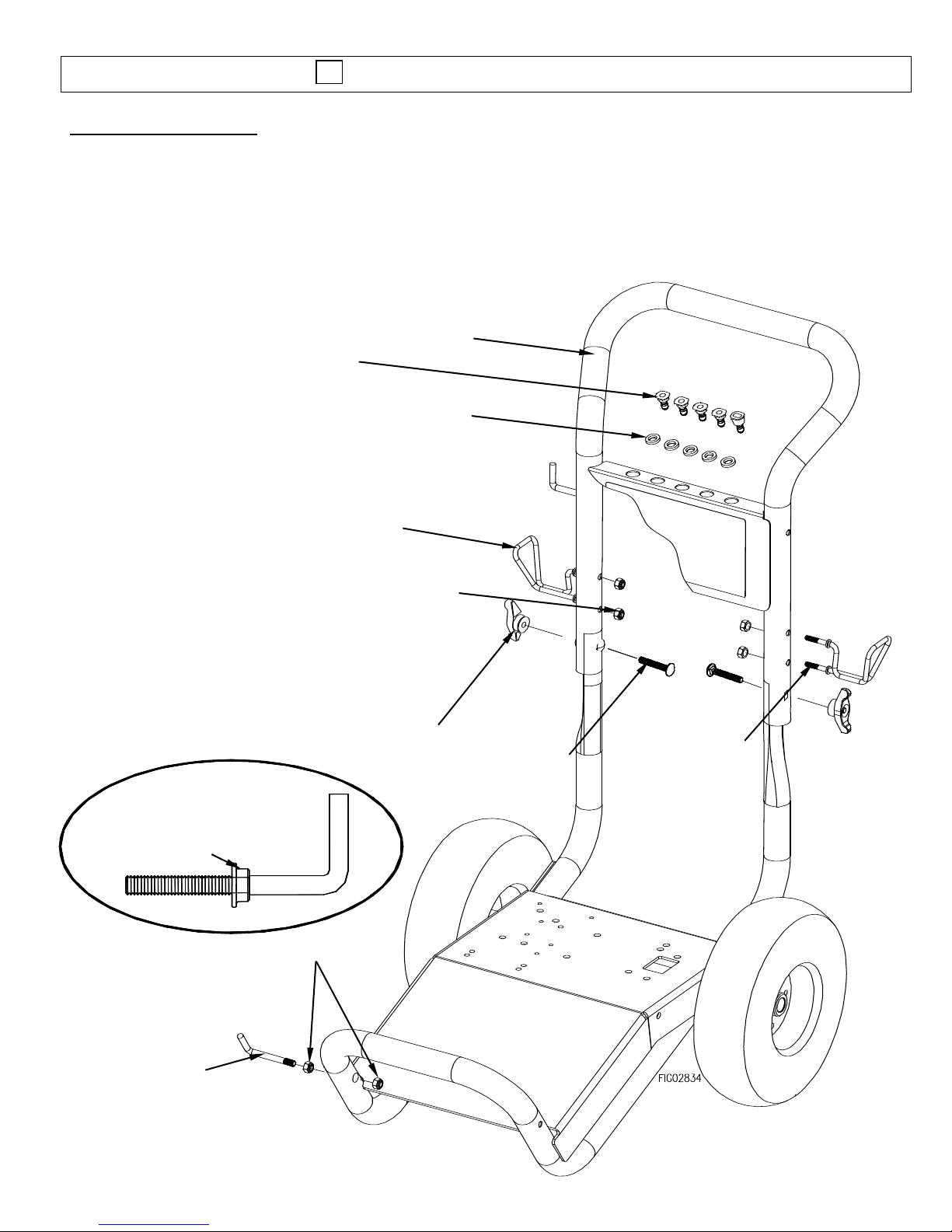
Assembly Instructions
9
Gun Hook
Flange nut
Hose hook
(Position A)
T-handle knob
Carriage bolts
Gun Hook Detail
Flange nut
Nozzles
(Quantities vary
by model)
Grommets
Handle
Hose hook
(Position B)
GC models only
Nylock nut
III.) Handle Assembly
1.) Attach handle to base with two carriage bolts and t-handle knobs.
2.) Spin a flange nut backwards onto the gun hook. (see hook detail)
3.) Mount the hose hook onto the handle and gun hook onto base as shown.
4.) Insert grommets into the holes on the handle nameplate.
5.) Press nozzles into grommets according to the colors indicated on the handle decal.
Page 10
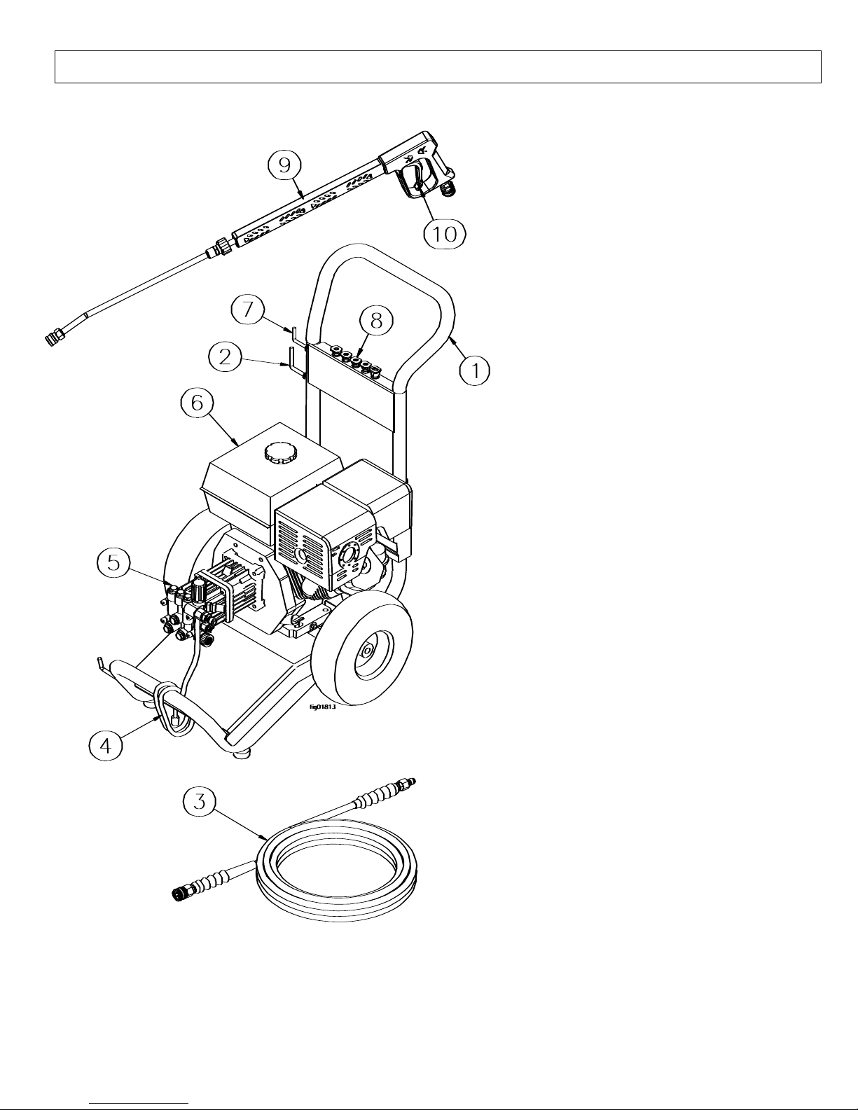
Machine Component Identification
10
*Note: Components on models vary slightly
1.) Handle. Designed for easy cart
movement.
2.) Hose Hook. Store hose on hook.
(Position depends on model, see
Assembly Instructions section.)
3.) Pressure Hose. Attach quick
couplers to gun and water outlet.
4.) Chemical Hose. Submerge in
cleaning solution.
5.) Water Pump. Inspect for
loose/broken parts prior to each use.
6.) Engine. Honda engine provides
years of reliable use.
7.) Gun Hook. Store gun on hook.
8.) Nozzles. Change nozzles for
different spray patterns
9.) Spray Gun. Always use two hands
for safe operation.
10.) Trigger. Actuate to allow
pressurized water to flow out of
spray gun.
Page 11
Operation Instructions
11
Page 12

Operation Instructions
12
Model
Time to fill 5 gallon bucket
1577543GN
100 seconds
1577544GN
100 seconds
1578172GN
100 seconds
1578182GN
84 seconds
1578202GN
72 seconds
Water Supply
1.) Make sure the water supply is clean. Debris can cause excess pump wear and reduce
performance.
2.) An insufficient water supply will damage your pump. Make sure the water supply is steady and is
20% over the rated flow of your pump. Use a stopwatch to time how long it takes to fill a 5-gallon
bucket with your garden hose. The bucket must fill faster than the times listed in the table below.
3.) The water supply garden hose must have an inside diameter of at least 5/8”. If the hose is more
than 100 ft. long, the diameter must be at least 3/4”.
4.) Never use a reservoir tank as a water source. Drawing water out of a tank may cause pump
cavitation and damage to your pump. This pressure washer is designed for a pressurized water
source such as a city water faucet. However, the water source pressure must not exceed 115 psi
(8 bar).
5.) Always use a flexible rubber hose for your water supply. Do not use rigid piping.
Page 13

Operation Instructions
13
Skin puncture hazard.
High pressure fluid can inject under skin resulting in serious injury including
amputation. Do not direct spray at people or animals.
-If skin injection happens, seek IMMEDIATE surgical treatment.
-Do not check for leaks with hand. Instead, use a piece of cardboard to check for
leaks.
-Do not use unit if exterior hose damage is evident. Make sure all fittings are tight
before starting. Relieve system pressure before servicing.
-Know how to stop engine and bleed pressures quickly. Be thoroughly familiar with
the controls.
-Make sure accessories meet the unit's temperature and pressure limits.
-Stop engine and bleed pressures before leaving unit unattended.
WARNING
Start-Up Instructions
1. Attach garden hose to water inlet.
2. Attach pressure hose to water outlet and gun.
3. Attach spray gun to lance.
4. Turn water supply ON.
5. Squeeze trigger to purge air from pump.
6. Insert nozzle.
7. Start engine.
Shut-Down Instructions
1. Turn engine OFF.
2. Turn water supply OFF.
3. Squeeze trigger to relieve system pressure.
4. Remove garden hose.
5. Remove pressure hose.
6. Turn fuel valve OFF (if equipped).
Page 14

Operation Instructions
14
spray gun
spray gun safety lock
lance
spin-on coupler
Spray Gun Safety Lock
When not spraying, use the spray gun safety lock to prevent accidental high pressure discharge.
* Note: Depending on model, gun may appear differently.
Attaching the Lance
Tighten spin-on coupler hand tight.
Note: The o-rings make the seal so there is no need to tighten with a wrench.
Installing Nozzles
Page 15

Operation Instructions
15
Flying objects.
Make sure nozzle is secure before squeezing trigger. If nozzle is not secure it will become a
projectile. Serious injury can occur.
WARNING
pump
hose
spray gun
CORRECT
INCORRECT
nozzle
collar
coupler
lance
collar completely
pushed out.
collar NOT completely
pushed out.
To install a nozzle pull back the collar and push the nozzle into the coupler. Once the connection
is made, pull on the nozzle to make sure it is secure.
Attach Quick Connect Couplers
-To install the hose onto the pump, pull back the collar and push the hose into the coupler on the
pump.
-To install the hose onto the spray gun, pull back the collar on the spray gun and push the hose
into the coupler on the spray gun.
Once the connections are made, pull on the hose to make sure it is secure.
Page 16

Operation Instructions
16
Risk of exposure to dangerous chemicals.
Serious injury or death can result if chemical manufacturer instructions are not
followed.
-Wear protective gloves when handling and cleaning with chemicals.
-Understand all safety hazards and first aid for all chemicals being used.
-When cleaning filters, check if chemicals have been used and take any
precautions that are recommended by the chemical manufacturer.
-Different chemicals may interact dangerously with each other, always follow
chemical manufacturer directions before switching chemicals.
-Calculate the correct amount of chemical to mix, dispose of excess chemical
per the manufacturer instructions.
-Never spray flammable liquids.
WARNING
Pump
Pump Outlet
Pump Inlet
Chemical Hose
Cleaning Solution
Strainer
Applying Chemicals
1.) Install the black nozzle to spray chemicals onto the cleaning surface.
2.) Start the pressure washer according to the start-up instructions.
3.) Submerge the chemical hose in cleaning solution. (See Pump Component Identification section
for chemical injector location.)
4.) Squeeze the spray gun trigger. The chemical injector will draw the chemical into the water
stream.
5.) Apply chemicals evenly onto the cleaning surface. Allow the chemicals to react with the dirt, then
clean at high pressure with green nozzle.
6.) Never use more chemical than is necessary to clean the surface.
7.) To clean the chemical injector, draw water through the strainer until all the chemical is purged
from the system.
Page 17

Maintenance and Storage
17
What to Check
When To Check
What to Do
Inlet Filter
Each Use
Visually inspect and clean inlet filter with clear water.
Pressure Hose
Each Use
Visually inspect pressure hose and hose couplings. Replace
hose if any of the following is evident:
hose coupling is damaged, wire mesh is exposed or
damaged, hose is permanently kinked or flattened, outer
hose cover is blistered or loose.
Bolts
Each Use
Tighten any loose bolts.
Engine Oil
See engine manual
See engine manual for oil change instructions
Pump Oil
After 1st 50hrs,
then 3mo/500hr
Change pump oil. See pump oil change instructions on next
page.
Maintenance Mode
Before performing any maintenance on the pressure washer, it must be placed in maintenance mode.
1.) Turn off engine.
2.) Turn off water supply.
3.) Squeeze trigger to relieve system pressure.
4.) Shut off fuel valve.
5.) Unplug spark plug wire from spark plug, (see engine owners’ manual).
Maintenance Schedule
Page 18

Maintenance and Storage
18
drain plug
sight glass
(other side)
Oil capacity: 3.4 oz. (.10 L)
Comet VRX 2528G Pump
fill cap
fill cap
fill cap
drain plug
drain plug
sight glass
sight glass
fill cap
Oil capacity: 8.5 oz. (.25L)
Cat 4DNX25GSI Pump
Oil capacity: 18 oz. (.53L)Oil capacity: 10.2 oz. (.30L)
sight glass
drain plug
Cat 3SPX30G1I Pump
fill cap
Cat 66DX35G1I Pump
Oil capacity: 4.3 oz. (.13L)
Comet AXD 2530 Pump
VRX:
Remove the bolts that connect the pump to the engine. Remove fill
cap and rotate pump upside down.
All other pumps:
Remove drain plug.
VRX:
Rotate pump to the upright position, and reinstall mounting bolts.
All other pumps:
Reinstall drain plug.
VRX:
Add specified capacity.
All other pumps:
Fill to middle of sight glass.
Pump Oil Change
1) Place a suitable container below the pump to catch the used oil.
2) Allow the used oil to drain completely.
3) Please dispose of used oil in a manner that is compatible with the environment. We suggest you
take used oil in a sealed container to you local recycling center or service station for reclamation. Do
not throw it in the trash, pour it on the ground or down the drain.
4) With the pump in a level position add oil to the pump (see capacities below). For Comet and GNE
pumps: Use Universal Tractor Transmission Oil (part# COCP2101) or Mobil1 15W50 synthetic oil.
For Cat pumps: Use SAE 30 non-detergent oil or Cat pump oil item # 22158.
Page 19

Maintenance and Storage
19
RV Antifreeze
Funnel
Hose
Water Inlet
Long Term Storage
Follow the engine owner’s manual for storing the engine.
Winter Storage
Protect your pump, hose, and gun from freezing.
Items needed: 12” piece of garden hose or equivalent, funnel and RV antifreeze (approximately 6 oz.)
1.) Follow the storage instructions listed above.
2.) Disconnect spark plug cable. Make sure the engine start switch is OFF and the fuel valve is OFF.
3.) Attach the garden hose with funnel to the pump inlet (see illustration).
4.) Pour RV antifreeze into the funnel, pull the engine recoil until antifreeze comes out the pump
outlet.
5.) Drain all water from the high pressure hose. Depress trigger on gun and drain all water out of
gun/lance.
Page 20

Troubleshooting
20
Problem
Engine will not start
SOLUTION: A,B
Low/Surging pressure or no water flow
SOLUTION: C,D,E,F,G,H
No chemical injection
SOLUTION: I,J,K,L
Cause
Solution
A- Low oil shutdown
See engine manual for oil requirements
B- Engine starting instructions not followed
See engine manual for starting instructions
C- Insufficient water supply
See water supply section of this manual
D- Plugged pump inlet filter
See maintenance section of this manual
E- Wrong nozzle
Make sure high pressure nozzle is being used
F- Plugged nozzle
Remove nozzle, check for blockage
G- Worn nozzle
Replace nozzle
H- Leak in pressure hose
Replace pressure hose
I- Wrong nozzle
Make sure chemical nozzle is being used
J- Back pressure from extra long discharge hose
Try shorter hose
K- Leak in chemical siphon hose
Replace hose – use hose clamps if necessary
L- Chemical strainer not submerged
Make sure strainer is completely submerged
The manufacturer reserves the right to make improvements in design and/or
changes in specifications at any time without incurring any obligation to install
them on units previously sold.
Any Questions, Comments, Problems or Parts Orders
Call GNE Product Support 1-800-822-0295
Page 21

Specifications
21
1578172GN
PSI (bar)
3000 (207)
GPM (l/min)
2.5 (9.4)
Max Water Temp
140F (60C)
Noise Level
78 dB
Dimensions
L x W x H
34” x 21” x 38”
(864mm x 534mm x 965mm)
Weight
96 lb (44kg)
1578182GN
PSI (bar)
3300 (227)
GPM (l/min)
3.0 (11.3)
Max Water Temp
140F (60C)
Noise Level
82 dB
Dimensions
L x W x H
34” x 21” x 38”
(864mm x 534mm x 965mm)
Weight
123 lb (55.8 kg)
1578202GN
PSI (bar)
4000 (275)
GPM (l/min)
3.5 (13.2)
Max Water Temp
140F (60C)
Noise Level
82 dB
Dimensions
L x W x H
34” x 21” x 38”
(864mm x 534mm x 965mm)
Weight
147 lb (66.7 kg)
1577544GN
PSI (bar)
3000 (207)
GPM (l/min)
2.5 (9.4)
Max Water Temp
140F (60C)
Noise Level
82 dB
Dimensions
L x W x H
34” x 21” x 38”
(864mm x 534mm x 965mm)
Weight
83 lbs (37.6 kg)
1577543GN
PSI (bar)
2800 (193)
GPM (l/min)
2.5 (9.4)
Max Water Temp
140F (60C)
Noise Level
75 dB
Dimensions
L x W x H
34” x 21” x 38”
(864mm x 534mm x 965mm)
Weight
77 lbs (35 kg)
Page 22

Parts Exploded View-Rev C
22
Item Numbers:
1578172GN, 1578182GN,
1578202GN, 1577543GN,
1577544GN,
* Depending on model, components may appear differently.
Page 23

Parts Exploded View-Rev C
REF#
PART#
DESCRIPTION
QTY
MODEL
1
38509
Gun Hook 1 All
2
789541GN
Decal 1 All
3
35198
Grommet 5 All
4
780223GB
Handle 1 All
5
779761
Hose hook 1 All
6
38578
Knob 2 All
7
779924GB
Base 1 All
8
12278
Wheel 2 All
9
305200
Wheel Retainer
2
All
10
38525
50’ Pressure Hose
1
1578172GN, 1578182GN,
1578202GN
38524
25’ Pressure Hose
1577543GN, 1577544GN
11
777915
Hose Quick Couple Nipple
1
All
12
777914
Hose Quick Coupler
1
All
13
780455
Spray Gun Quick Coupler
1
All
14
779168
Spray Gun Handle
1
1578172GN, 1578182GN,
1578202GN
15
22622
Lance w/ Quick Connect
1
1578172GN, 1578182GN,
1578202GN,
16
779165
Spray Gun
1
1578172GN, 1578182GN,
1578202GN,
38527
1577543GN, 1577544GN
17
779166
Lance 1 All
18
777904
Nozzle Quick Coupler
1
All
19
38530
Nozzle 2 Pack #3.0
Nozzle 5 Pack #3.0
Nozzle 5 Pack #3.5
1
1577543GN, 1577544GN
38531
1578172GN
38532
1578182GN,1578202GN
20
221222
Chemical Strainer
1
All
21
777165
Braided Chemical Hose (sold by foot)
4 ft
All
22
2215
Rubber Foot 2 All
23
781026
Burn Hazard Decal
1
All
25
GNEGX160
Honda GX 160 Engine
1
1578172GN
GNEGX270
Honda GX 270 Engine
1578182GN
GNEGX390
Honda GX 390 Engine
1578202GN
GNEGC160
Honda GC 160 Engine
1577543GN
GNEGC190
Honda GC 190 Engine
1577544GN
26
790692
789205
788598
38520
779827
Comet AXD 2530G Pump
1
1577544GN
1578172GN
1578182GN
1578202GN
1577543GN
Cat 4DNX Pump
Cat 4SPX Pump
Cat 66DX Pump
Comet VRX Pump
23
Page 24

Pump Explosions
24
Page 25

Pump Explosions-cont’d
REF#
PART#
DESCRIPTION
QTY
MODEL
26
790692
Comet AXD 2530G Pump
1
1577544GN
789205
Cat 4DNX Pump
1578172GN
788598
Cat 3SPX Pump
1578182GN
38520
Cat 66DX Pump
1578202GN
779827
Comet VRX 2528G Pump
1577543GN
27
777915
Quick Connect Outlet Plug
1
All
28
4027
Inlet Filter Washer
1
1577543GN
38596
3/8” Inlet Filter
1578172GN,1578182GN
35169
1/2” Inlet Filter
1578202GN
29
777340
¼” x ¼” Hose Barb Fitting
1
1578172GN,1578202GN
30
777834
¼” Hose Clamp
2
1578172GN,1578182GN,
1578202GN
31
777165
¼” PVC Hose (sold by foot)
1 ft
1578172GN,1578182GN,
1578202GN
32
38584
Easy Start Valve
1
1578172GN,1578182GN,
1578202GN
33
777347
3/8” Street Tee
1
1578172GN,1578182GN,
1578202GN
34
35918
Thermal Valve
1
1578172GN,1578182GN
777836
1578202GN
35
777376
Pop Off Valve
1
1578182GN, 1578202GN
44
777410
3/8 Street elbow
3
1578182GN
1
1578202GN
25
Page 26

Comet AXD Pump Exploded View
26
Page 27

Comet AXD Pump Exploded View
Ref #
Part #
Description
Qty
Ref #
Part #
Description
Qty
1
CO3202001800
CAP
1 39
CO3200001700
PORT PLUG, AXD COMET PUMP
1
2
CO3609001400
SCREW, M8 X 55
4 40
CO2409009100
PISTON CHECK VALVE KIT,AXD UNL
1
3
NOT AVAILABLE
MANIFOLD
1 41
CO1210046000
O-RING 1 4
CO3202001800
CAP
1 42
CO2409008600
CHECK VALVE
1
5
CO1210004900
O-RING,OIL PLUG - WOBBLE
PUMP
6 43
CO1802019700
SPRING
1
6
SEE PART # 10
VALVE SEAT
6 44
CO3410034800
INJECTOR BODY KIT
1
7
CO3604002800
SUCTION/DEL. VALVE
6 45
CO1210004900
O-RING,OIL PLUG - WOBBLE PUMP
1
8
CO1802019200
SPRING, AXD
6 46
CO1210004000
O-RING, AXD
1
9
CO1205003300
VALVE CAGE, AXD
6 47
CO3410032900
INJECTOR BODY
1
10
CO1220004500
VALVE - AXD PUMP
6 48
CO2803043700
OUTLET FITTING, QUICK CONN.WO
1
11
CO0601027300
AXD SPACER
2 49
CO1215035400
THERMOVALVE
1
12
CO1210015100
O-RING, AXD3020
6 50
CO0608003000
KIT EASY START
1
13
CO3202031100
VALVE CAP & O-RING
6 51
CO8102045000
FILTER WASHER
1
14
CO1817006400
HANDLE
1 52
CO1223010800
GARDEN HOSE NUT
1
15
CO1215058500
REG.VALVE KIT & SEAT
1 53
SEE PART # 54
SPECIAL COUPLING - NLA
1
16
CO1241005900
PACKING - GXD1617
3 54
CO2800051100
GARDEN HOSE TAIL W/WING NUT
1
17
CO0009036900
RING
3 55
SEE PART # 58
CHEM. COUPLING
1
18
CO0009021900
RING(RETAINER) - WOBBLE
PUMP
3 56
CO3003002400
BALL FOR CHEMICAL INJECTOR
1
19
CO1210035600
O-RING,SEAL CONTAINER WOBBLE
3 57
CO1802018000
SPRING FOR CHEMICAL INJECTOR
1
20
CO1241005700
BACK PACKING
3 58
CO2803043500
CHEMICAL INJECTOR KIT
1
21
CO0601030800
OIL SEAL SPACER
3 59
CO3200001700
PORT PLUG, AXD COMET PUMP
1
22
CO0019005800
SEALING RING(OIL) - WOBBLE
PLA
3 70
CO0001039500
DRIVESHAFT
1
23
CO3201002700
OIL SIGHT GLASS
1 71
CO1210042900
O-RING FOR AXD
1
24
CO1210004800
O-RING, 2.62 X 20.24MM
1 72
CO0019003400
SEALING RING - AXD PUMP
1
25
NOT AVAILABLE
PUMP CRANKCASE
1 73
NOT AVAILABLE
SUPPORT
1
26
CO2409015600
PISTON KIT
3 74
CO3607016800
HEXAGONAL SCREW
4
27
CO1802015300
SPRING, AXD
3 75
CO2811000200
WASHER
4
28
CO2409008900
PISTON - AXD3020G
3 76
CO3200007100
OIL PLUG
1
29
CO0009022100
RING FOR AXD
3
30
CO0009022000
14MM RING FOR AXD
3 31
CO0438007600
BALL BEARING - AXD
1 32
CO0001041700
ECCENTRIC SHAFT - AXD
1 33
CO3609000500
SCREW, M8 X 20 - AXD
1 34
CO0436001700
BEARING
1
35
CO2816008800
THRUST BEARING
1
36
CO3609002800
SCREW M8 X 22
4 100
CO5025001400
VALVE KIT - AXD3020G
1
37
CO1209011700
GASKET -2527
1 101
CO5019007700
SEAL KIT - AXD3020G
1
38
CO3200009600
PLUG 1/4"
1 102
CO5019007900
SEAL KIT, AXD
1
27
Page 28

Pump Exploded View- Cat 4DNX Pump
Ref#
P/N
DESCRIPTION
QTY
Ref#
P/N
DESCRIPTION
QTY
5
Not Available
Screw 3 106
Kit #1
Seal
3
8
CA547153
Bearing Cover
1
120
Not Available
Seal Case
3
10
CA14041
O-Ring, Bearing Cover
1
121
CA13976
O-Ring for Seal Case
3
11
CA55337
Oil Seal
1
125
Kit #1
Seal
3
15
CA14488
Inner Ball Bearing
1
160
CA17428
O-Ring, Inlet
3
20
CA547048
Connecting Rod
3
161
CA547077
Seat, Inlet
3
24
Not Available
Oil Plug Cap
1
162
CA48361
Back-up Ring
3
25
CA549446
Crankshaft
1
163
CA43358
O-Ring
3
27
CA56084
Ball Bearing
1
164
CA547076
Seat, Discharge
3
32
CA547961
Cap 1 166
CA547098
Valve 6 33
CA14179
O-ring for Oil Filter Cap
1
167
CA46865
Spring 6 37
CA92241
Gauge, Bubble Oil w/Gasket
1
168
CA543988
Retainer, Spring, Inlet
3
38
CA44428
Gasket, Flat Flex Oil Gauge
1
169
Kit #2
Retainer, Spring, Discharge
3
48
CA44842
Drain Plug
1
172
CA142807
O-Ring for Plug
3
49
CA14179
O-Ring for Drain Plug
1
174
CA547104
Plug, Valve w/o-ring
3
53
Not Available
Crankcase
1
185
Not Available
Head, Manifold w/Unloader Body
1
64
CA46229
Crosshead Pin
3
188
Not Available
Screw 6 65
CA542402
Plunger Rod
3
197
CA941516
Inlet Fitting Assembly
1
70
CA47215
Oil Seal
3
249
CA30520
Adapter Mount Assembly
1
90
CA547091
Plunger
3
255
CA30516
Bolt Mount Assembly
1
98
CA46730
Washer
3
469
CA7332
Chemical Fixed Injector
1
99
CA542405
Retainer, Plunger
3
KITS
100
CA46233
Retainer, Seal
3 Kit#1
CA76975
Seal Kit: Inclds: 98, 106, 121, 125
1
*One Kit will Complete One Pump*
Kit#2
CA76976
Valve Kit: Inclds: 160, 161, 162,
163, 164, 166, 167, 168, 169, 172
1
28
Page 29

Pump Exploded View- Cat 66DX
29
Page 30

Pump Exploded View- Cat 66DX
Ref#
P/N
DESCRIPTION
QTY Ref#
P/N
DESCRIPTION
QTY 5 Not Available
Screw 3 188
Not Available
Screw 6 8
CA547084
Bearing Cover
1
249
CA31643
Adapter Mount Assembly
1
10
CA14041
O-Ring, Bearing Cover
1
401
CA547797
Handle, Adjusting
1
11
CA125351
Oil Seal
1
402
CA547798
Adjusting Cap
1
15
Not Available
Inner Ball Bearing
1
403
CA548671
Lock Nut
1
20
CA547020
Connecting Rod
3
404
CA548675
Screw, Set
1
24
Not Available
Oil Plug Cap
1
408
CA32094
Pressure Spring
1
25
Not Available
Crankshaft
1
410
CA549352
Spring Retainer
1
26
Not Available
Ring, Retaining
1
412
CA45694
Piston Stem
1
27
CA15710
Ball Bearing
1
414
CA20184
Back Up RIng
1
32
CA547961
Cap 1 415
CA14190
O-Ring, Piston Stem
1
33
CA14179
O-ring, 70D (for Oil Filter Cap)
1
423
CA46249
Retainer Valve
1
37
CA92241
Gauge, Bubble Oil w/Gasket
1
424
CA13966
O-Ring, Valve Retainer (Outer)
1
38
CA44428
Gasket, Flat Flex Oil Gauge
1
425
CA547799
Piston Retainer
1
48
CA44842
Drain Plug
1
426
CA46250
Washer 1 49
CA14179
O-Ring, 70D (for Drain Plug)
1
428
CA26133
O-Ring, 80D (for Piston Retainer)
1
53
Not Available
Crankcase
1
429
CA17399
O-Ring, Valve Retainer (Inner)
1
64
CA16948
Crosshead Pin
3
435
CA547800
Valve 1 65
CA548872
Plunger Rod
3
436
CA49664
Seat 1 69
CA126259
437
CA13963
O-Ring, 70D (for Seat)
1
70
CA25301
Oil Seal
3
438
CA46254
Seat, Check Valve
1
90
CA547091
Plunger
3
439
CA13963
O-Ring, 70D (for Check Valve Seat)
1
98
CA46730
Washer
3
443
CA547826
Valve, Check
1
99
CA542405
Retainer, Plunger
3
444
CA45924
Spring 1 100
CA44869
Retainer, Seal
3 446
CA26133
O-Ring, 70D (for Body)
1
106
CA45188
Seal 3
469
CA7332
Chemical Fixed Injector
1
120
CA49942
Seal Case
3 470
CA76179
Unloader Repair Kit Inclds: 412, 414,
415, 423, 424, 425, 426, 429, 431,
435, 436, 437
1
121
CA13977
O-Ring for Seal Case
3 471
CA76146
Check Valve Kit Inclds: 438, 439, 443,
444, 446
1
122
CA49943
Ring, Support
3 472
Not Available
Barb
1
125
CA49824
Seal 3
476
See # 483
O-ring, Barb
1
160
CA17428
O-Ring, Inlet
3 477
See # 483
Ball 1 161
CA547077
Seat, Inlet
3 478
See # 483
Spring 1 162
CA48361
Back-up Ring
3 479
Not Available
Orifice 1 163
CA43358
O-Ring
3 480
Not Available
Body 1 164
CA547076
Seat, Discharge
3 483
CA76176
Kit, Repair Inclds: 476, 477, 478
1
166
CA547098
Valve 6
Kit #1
CA76977
Seal Kit Inclds: 98, 106, 121, 125
1
167
CA46865
Spring
6 Kit #2
CA76976
Valve Kit Inclds: 160, 161, 162, 163,
164, 166, 167, 168, 169, 172
1
168
CA543988
Retainer, Spring, Inlet
3 Kit #3
CA31767
O-Ring Kit Inclds: 414, 415, 424, 429,
437, 439, 446)
1
169
CA49764
Retainer, Spring, Discharge
3
172
CA142807
O-Ring for Plug
3
174
CA547104
Plug, Valve w/o-ring
3
185
Not Available
Head, Manifold w/Unloader Body
1
30
Page 31

Pump Exploded View- Cat 66DX
Page 32

Pump Exploded View- Comet VRX
Ref #
Code
Description
Qty
Ref #
Code
Description
Qty
1
2801 0079
Thermo Valve Cover
1 39
2432 0018
Pump Crankcase
1 2 1210 0218
O-Ring
1 40
1802 0213
Piston Spring
3 3 0424 0402
Thermal Valve Body
1 41
2409 0099
Piston
3
4
1210 0475
O-Ring
1 42
0009 0267
Ring 3 5
3230 0031
Sensor
1 43
5026 0260
Piston Kit
3 6 1802 0217
Spring
1 44
1210 0391
O-Ring
1 7 1002 0116
Suction Filter
1 45
1210 0463
O-Ring
1 8 2803 0395
Quick Coupler
1 46
2409 0102
Check Valve
1 9 1223 0093
Wing Nut
1 47
1802 0218
Spring
1
10
2800 0096
Straight Hose Tail Kit
3 48
5026 0262
Check Valve Kit
1
11
3218 0351
Pump Manifold
1 49
1210 0465
O-Ring
1
32
Page 33

Pump Exploded View- Comet VRX
12
3609 0195
Screw
3 50
0801 0066
Detergent Injector
1
13
3202 0276
Plug
1 51
1210 0170
O-Ring
1
14
1802 0219
Regulation Valve
Spring
1
52
1410 0322
Detergent Injector Kit
1
15
2811 0117
Washer
1
53
0204 0051
Bushing
1
16
3605 0104
Special Screw
1
54
1802 0216
Spring
1
17
1210 0392
O-Ring
1
55
3003 0033
Ball 1 18
1210 0470
O-Ring
1
56
1210 0466
O-Ring
1
19
0009 0272
Ring 1 57
1210 0465
O-Ring
1
20
1210 0055
O-Ring
1
58
2800 0104
Detergent Straight
Hose Tail
1
21
3021 0034
Elastic Pin
1
59
5026 0261
Complete Detergent
Kit
1
22
0015 0187
Valve Rod
1
60
0436 0020
Axial Ball Bearing
1
23
1210 0465
O-Ring
1
61
0001 0460
Throu-Eccentric Shaft
1
24
0009 0112
Backup Ring
1
62
1210 0394
O-Ring
1
25
1215 0334
Regulation Valve Kit
1
63
0438 0081
Ball Bearing
1
26
3009 0136
Regulation Valve
Seal
1
64
0031 0012
Pump Crankshaft
1
27
1210 0170
O-Ring
1 65
0019 0112
Oil Seal
1
28
3003 0032
Ball
1 66
0403 0156
Pump Crankcase
1
29
5026 0269
Regulation Valve
Seat Kit
1 67
3200 0071
Plug
1
30
1220 0061
Delivery Valve
2 68
2417 0064
Extension
1
31
1220 0062
Delivery Valve
1 69
1210 0492
O-Ring
1
32
3302 0279
Plug
3 72
0604 0015
Nut 3 33
1241 0068
Packing
3 73
3016 0042
Support
1
34
0009 0274
Anti-Extr. Ring
3 74
3625 0062
Screw
4
35
2811 0004
Washer
3 100
0009 0225
Anti-Extr. Ring
1
36
0009 0270
Packing Retainer
3 103
3000 0781
Oil Seal Spacer
3
37
0019 0111
Oil Seal
3 104
5026 0276
Thermo Valve Kit
1
38
1220 0061
Suction Valve
3 105
3200 0093
Oil Tap Kit
1
Part #
Code
Qty
30
1220 0061
2
31
1220 0062
1
38
1220 0061
3
Part #
Code
Qty
33
1241 0068
3
34
0009 0274
3
Piston Seal Kit (502602556)
Complete Valve Kit (50260270)
33
Page 34

Limited Warranty
Item #
Warranty Period
1577543, 1577544
2 years for noncommercial/nonrental use and a period of 90 days for
commercial/rental use from the date of purchase by user
1578172, 1578182, 1578202
2 years from date of purchase by user
Dear Valued Customer:
The GNE Product you just purchased is built with the finest material and craftsmanship. Use this product
properly and enjoy the benefits from its high performance. By purchasing a GNE product, you show a desire for
quality and durability. Like all mechanical equipment this unit requires a due amount of care. Treat this unit like the
high quality piece of machinery it is. Neglect and improper handling may impair its performance. Please thoroughly
read the instructions and understand the operation before using your product.
Limited Warranty
GNE shall warranty any piece of equipment manufactured for, or parts of equipment manufactured for GNE, to be free
from defects in material or workmanship for a period of:
GNE shall warranty any wear item, including, but not limited to, valves, seals, pump diaphragms, hoses, and filter
elements to be free from defects in material or workmanship for a period of 90 days from the date of purchase by user.
This warranty applies to the original purchaser of the equipment and is non transferable. Verification of purchase is the
responsibility of the buyer. Parts will be replaced or repaired at no charge, except when the equipment has failed due to
lack of proper maintenance. Any misuse, abuse, alteration or improper installation or operations will void warranty.
Determining whether a part is to be replaced or repaired is the sole decision of GNE.
NOTE: Some services performed by parties other than GNE may void warranty.
This warranty covers parts only. It will not provide for replacement of complete products due to defective parts.
Components not manufactured for GNE are guaranteed by their manufacturer and can be serviced at factoryauthorized locations near you. Any costs incurred due to replacement or repair of items outside of a GNE
approved facility is the responsibility of the buyer and not covered under warranty. GNE can supply you with
the service center location in your area.
This warranty specifically excludes the following; failure of parts due to damage caused by accident, fire, flood,
windstorm, acts of God, applications not approved by GNE in writing, corrosion caused by chemicals, use of
replacement parts which do not conform to manufacturer’s specifications, and damage caused by vandalism. Additional
exclusions: loss of running time, inconvenience, loss of income, or loss of use, including any implied warranty of
merchantability of fitness for a specific use.
Warranty does not cover items subject to normal wear such as tires, receptacles or any part subject to direct physical
contact by the public. This warranty does not cover any personal injury or damage to surrounding property caused by
failure of any part.
This warranty is in lieu of any other warranty expressed or implied and GNE assumes no other responsibility or liability
outside that expressed within this warranty.
Please fill in the following information and have it on hand when you call in on a warranty claim.
Customer Number: ______________________________________________________________
Date of Purchase: _______________________________________________________________
Product Serial Number: _______________________________________________________
Item Number: __________________________________________________________________
34
Page 35

This page was intentionally left blank.
35
Page 36

Distributed by:
GNE
20195 S. Diamond Lake Rd., STE 100
Rogers, MN 55374
36
 Loading...