

PRESENTATION OF MANUAL
INSTRUCTIONS FOR USE
Technical Name: Dental Delivery Units
Trade Name: Syncrus G3 H Delivery Unit
Brand: GNATUS
Manufacturer/ Distribuitor:
GNATUS - EQUIPAMENTOS MÉDICO-ODONTOLÓGICOS LTDA.
Rod. Abrão Assed , Km 53+450m - Cx. Postal 782 CEP 14097-500
Ribeirão Preto - S.P. - Brasil
Fone +55 (16) 2102-5000 - Fax +55 (16) 2102-5001
C.N.P.J. 48.015.119/0001-64 - Insc. Est. 582.329.957.115
www.gnatus.com.br - gnatus@gnatus.com.br
Technical Duties: Gilberto Henrique Canesin Nomelini
CREA-SP: 0600891412
Registration ANVISA #: 10229030047
ATTENTION
For greater safety:
Read and understand all the instructions contained in these
instructions for use before installing or operating this equipment.
Note: These instructions for use must be read by all the operators
of this equipment.
2

INDEX
PRESENTATION OF MANUAL ........................................................................02
IDENTIFICATION OF EQUIPMENT .................................................................04
- Indication of Equipment ................................................................................04
- Principles and bases applied to the functioning of the product..............................04
- Description of Equipment ...............................................................................05
MODULES, ACCESSORIES, OPTIONS AND MATERIALS OF CONSUMPTION .....07
TECHNICAL SPECIFICATIONS .......................................................................10
- Technical features of the Delivery Unit and its accessories ...................................10
- Electromagnetic emissions ..............................................................................12
- Dimensions ..................................................................................................16
- Packing symbols ...........................................................................................17
- Product symbols ...........................................................................................17
- Standards applied .........................................................................................19
- Content of acessible and non-accessible demarcations .......................................19
INSTALLATION OF EQUIPMENT ....................................................................19
OPERATION OF EQUIPMENT .........................................................................19
PRECAUTIONS, RESTRICTIONS AND WARNINGS ..........................................28
- Transportation, storage and operation ..............................................................28
- Sensitivity to environmental conditions in normal situations of use .......................28
- Precautions and warnings “during the installation” of equipment ..........................28
- Recommendations for the dental equipment maintenance. ..................................29
- Precautions and warnings “during the use” of equipment ....................................29
- Precautions and warnings “after” the use of equipment ......................................29
- Precautions and warnings during the “cleaning and disinfection” of equipment .......30
- Precautions in case of alteration in the functioning of equipment ..........................30
- Precautions to be adopted against foreseeable or uncommon risks,
related to the deactivation and abandoning of equipment ......................................30
CORRECTIVE AND PREVENTIVE MAINTENANCE AND PRESERVATION............31
- Additional procedures for reuse .......................................................................31
- Cleaning ......................................................................................................31
- Disinfection ..................................................................................................31
- Preventive Maintenance .................................................................................33
- Corrective Maintenance ..................................................................................33
UNFORESEEN EVENTS – SOLUTION OF PROBLEMS ........................................34
WARRANTY OF EQUIPMENT ..........................................................................35
FINAL CONSIDERATIONS ..............................................................................35
33

IDENTIFICATION OF EQUIPMENT
Dear Customer
Congratulations. You have made a good choice when you decided to buy a GNATUS
QUALITY product comparable to the best products available in the World. This manual is a
general presentation of your product and it will give you important details to help you to
solve possible problems.
Please, read it and keep this with you.
Indication of Equipment
This equipment is for dental use use only. It must be operated and utilized by specialized
professional (certied professional, according to the legislation of the country) and following
the instructions of the manual. The operation of the equipment required, for the professional,
the utilization of correct instruments and it should to be in perfect conditions of the use,
and to protect the professional, the patients and others, in the eventual danger situation.
Principles and bases applied to the functioning of the product
It has hoses with compressed air and connectors for the supply of handpieces (high and
low rotation) and a syringe with air and water outlet.
Identication
Technical Name: Dental Delivery Units and Accessories
Trade Name: Syncrus G3 H Delivery Unit
Brand: GNATUS
Illustrative image.
4

IDENTIFICATION OF EQUIPMENT
Description of Equipment
Dental use equipment, for actuation and control of the syringe, rotary instruments and
others, providing the best proximity to the operative eld; ambidextrous (serves right and
left-handed users).
Set made of steel structure with ABS body injected with anti-UV protection. Flat paint
high gloss epoxy-based, cured in an oven at 250 ° C, with phosphate treatment corrosion
resistant and cleaning materials.
FLEX type pneumatic Model with stroke limiter stop. Attached to the chair, with wide
horizontal and vertical movement, with pneumatic locking, powered by button located
under the handle of the equipment, providing smoothness in movements and stop at the
desired position.
Movement of tips through retractable rods with lock for relief in the tension of the hose
(except from triple syringe Stem), which provides lightness of movements, allowing greater
proximity to the operative eld
Automatic selection of tips through individual pneumatic valves, allowing lightness in
your drive.
Flexible support for hand pieces is removable and autoclavable, protecting them against
impact
Smooth Hoses, rounded, light and exible, without grooves or ridges.
Support for tray attached to the catheter with horizontal movements.
Bilateral handles.
* Equipped with side control panel contains a set of all commands for the chair, equipment
functions, water unit and light reector.
* Bio-System: Disinfection system provided with check valve, which provides the internal
cleaning hoses and terminals with bactericidal liquid, preventing risk of cross contamination.
To ensure safe operation of your equipment, use only assembly congurations (Chair,
Equipment, Water Unit and Light reector) provided by Reseller / Gnatus Authorized Service.
ISO 9001 and ISO 13485 Quality system, ensuring that products are manufactured
within standard procedures.
Products are manufactured according to the RDC 16/13 - National Health Surveillance
Agency – ANVISA resolution.
* Curing Light
Product Features:
Designed to carry out curing resin material through a curing process. The wavelength
of 440nm - 460nm associated with high energy emitted by Curing Light enables the multifunctionality of this device.
It has high power LED with efcient coupling and optical distribution, providing speed
and security procedures. Ensures proper photo-activation of materials without wasting light.
The LED system of this machine has long service life, equivalent to 36 million 10-second
cycles without loss of power and efciency in the photo activation.
The reduced weight of the pen and its anatomical design ensure a more comfortable
and practical professional work.
Operation control with display and buttons on the pen itself.
Programmable operating time.
- 10, 20, 40, 60, 80 and 90 seconds with sound signal (beep) every 10 seconds.
- Shows the elapsed time and the end of the operation.
- No special optical lters.
- Low power consumption.
* Optional
55

IDENTIFICATION OF EQUIPMENT
- Low cost of replacement.
The cold light does not emit heat as conventional bulbs - Low temperature light
polymerizes the resin without damaging the tooth pulp and prevents thermal expansion
problems.
- The forced ventilation system, transmitting unpleasant noise is not necessary.
- High strength piece
Conductive light removable tip, made of high strength polymer and easy maintenance
- Suitable for single bleaching or up to three teeth.
Swivel eye protection - Ensures full protection without compromising the visual eld.
*Ultrasound
Product Features:
Piezoelectric Ultrasound, frequency of 30,000 Hz.
The transducer with piezoelectric system allows the insert to perform accurate movements
and linear and can be used in various dental specialties.
Fine power adjustment, suitable for each type of procedure.
For proceedings with refrigeration provides constant irrigation with ow control. It also
allows the execution of dry work (amalgam condensation, cementing inlays / on lays, etc.).
*Digital Control Panel Kit "electric micro motor Bien Air"
Product Features:
See Owner's Manual - Digital control panel
*Bicarbonate jet SET/ Hand Jet
Product Features:
See Owner's Manual – Hand jet
* Optional
6

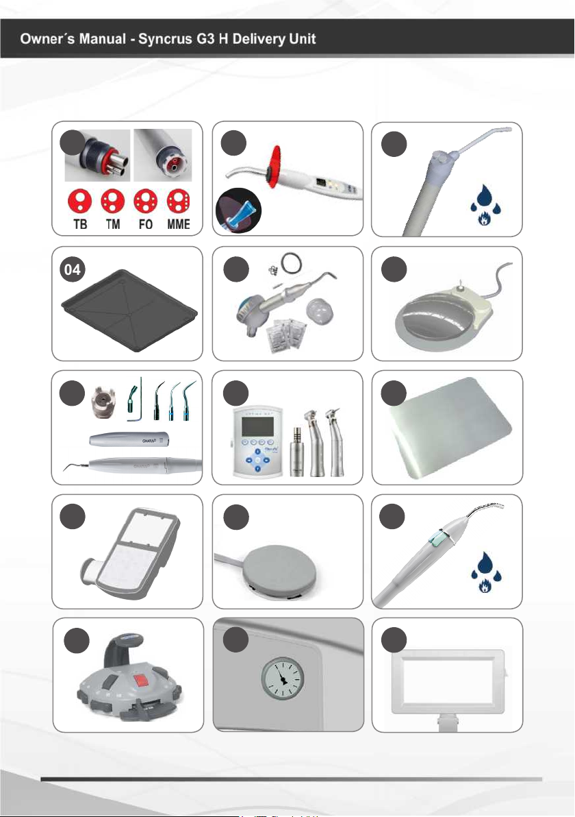
MODULES, ACCESSORIES, OPTIONS AND MATERIALS
OF CONSUMPTION
The contents of this page are of an informative nature, the equipment being able to differ
from that illustrated. So, upon acquiring the product check the technical compatibilty
between equipment, coupling and accessories.
07
A
14
16
15 15 15
01
02
03
09
08
08
06
05
B
A
04
B
10 12 1311
01 - Bilateral Catcher
02 - Triple syringe
*
03 - High-speed-motor terminals
*
04 - Micro motor terminal
*
05 - Control panel (PAD)
*
06 - X ray view
*
07 - Auxiliary tray
08 - Articulated arm
* Optional
09 - Column arm
10 - Power (power ultrasound adjustment)
*
11 - Speed (electric microengine power adjustment)
*
12 - Light (electric microengine brightness adjustment)
*
13 - Manometer
*
14 - Arm brake valve
15 - Water records for FO/MME/Ultrasound
*
16 - Bio-System operation
*
77
MODULES, ACCESSORIES, OPTIONS AND MATERIALS
OF CONSUMPTION
01
04 05
10 12
02
11
03
06
0907 08
13
14
15
8
MODULES, ACCESSORIES, OPTIONS AND MATERIALS
OF CONSUMPTION
01. Terminals:
*
16
The drawings (page 08
and 09) illustrates all
optional items; therefore,
your equipment will
consist only of items
selected during your
purchase option.
The use of any part,
accessory or material
not specied or foreseen
in these instructions for
use is entirely the user’s
responsibility.
Borden terminal (TB)
Midwest Terminal (TM)
Fiber Optic Terminal (FO)
Electric micro motor Terminal (MME)
02. Curing Light + tip for 3 teeth
*
(OPTI)
03. Triple syringe with fully metal
*
body or injected thermoplastic handle
"optional heater set"
04. Auxiliary Tray /
*
instrument support
05. Bicarbonate Jet set, Hand (JET)
*
06. Progressive pedal with drive / water
*
cut
07. Ultrasound set (SONIC)
*
08. Digital control panel set MME Bien
*
Air (FULL)
09. Stainless steel cover
*
10. Control panel with built-in
*
negatoscope (PAD)
11. Progressive Pedal
*
12. Triple syringe with fully injected
*
thermoplastic body "optional heater
set"
13. Integrated Pedal "Chip Blower"
*
14. Manometer
*
15.Negatoscope set
*
16.MME Bien Air set (MME)
*
* Optional
Equipment conguration
Equipment with nomenclature "FULL" may
contain some optional in the set, such as:
FO / MME / OPTI / SONIC /PAD, etc. ...
99
TECHNICAL SPECIFICATIONS
Technical features of the Delivery Unit and its accessories
General
Model
Syncrus G3 H Delivery Unit
Classication of Equipment as per ANVISA:
Class II
Classication of Equipment as per standard IEC 60601-1:
Protection against Electric Shock - Type B and Class I Equipment (IEC 60601-1)
Power Supply
Power Supply Voltage (coming from dental chair)
127/220 V~ (Selectable)
Frequency
50/60 Hz
Input fuse (coming from dental chair)
5A Delayed action
Voltage in equipment (coming from dental chair)
12 and 24 V~
Other specications
Inlet air pressure
60 a 80 PSI ±2
Capacity of reservoir - Water / Bio-System* (coming from water unit)
1000 ml* / 800 ml*
Maximum capacity of load applied to trays
1Kgf
Net weight
26 Kg
Gross weight
31 Kg
Dimensional support tray (mm)
385 x 300
* Optional
10

TECHNICAL SPECIFICATIONS
Specications of Curring Light
Power
5,2VA
Light source
1 LED
Active medium
Semicondutor Led (InGaN)
Wavelength
440nm - 460nm
Timer
90 seconds
Timer alarm
Sound alarm with beep every 10 seconds and 4 beeps at the end of the cycle
Activation
Through the hand-piece button
Light conductor
Made out of special polymer, rotational, removable and reuse sable.
Hand-piece body
ABS injected
Specications of Ultrasound
Transducer protective cover, removable and autoclavable.
Autoclavable tool to replace the inserts.
Frequency of Vibrations of Ultrasound
30.000Hz
Consumption of irrigating liquid
28 ml/min
Power consumed
15VA ±10%
Transducer system
Piezoelectric ceramic
Electronic circuit with frequency stabilizer.
Keeps the vibration even when there is network voltage oscillation.
1111
TECHNICAL SPECIFICATIONS
Pay attention while using this equipment together with other movable equipment, in
order to avoid collisions.
The materials used to produce the equipment are Biocompatible.
Use of different cables, transducers and accessories from those specied may result
in increased emissions or decreased immunity of the equipment.
Electromagnetic Emissions
Eletromagnetic emissions
The is made to be used in the electromagnetic environments specified below. The
equipment
client or theuser of the must be sure that it is used in such environment.
equipment
Emission test Compliance
RF emissions
ABNT NBR IEC CISPR 11
RF emissions
ABNT NBR IEC CISPR 11
Emissions of harmonics
IEC 61000-3-2
Fluctuation of Voltage /
Emissions of flicker
IEC 61000-3-3
Group 1
Class B
Class A
As per
Eletromagnetic environment - Guide
This equipment uses RF energy only for
internal functions. However,its
emissions are too low and it's unlikely to
cause any interferenceinthe
equipments next to it.
This equipment is proper to be used in
all establishments; including domestic
settings and those directlyconnecttoa
public low voltage distribution which
feeds domestic buildings.
12
TECHNICAL SPECIFICATIONS
Electromagnetic Emissions
Guidelines and manufacturer's declaration - electromagnetic immunity
The is made to be used in the electromagnetic environments specified below. The
equipment
client or theuser of the must be sure that it is used in such environment.
equipment
Immunity
test
Electrostatic
discharge(ESD)
IEC 6100-4-2
Quick electric
transitory phases /
train of pulses
(”Burst”)
IEC 61000-4-4
Surges
IEC 61000-4-5
Reduction,
interruption
and variance of
voltage in
power supply
input lines
IEC 61000-4-11
Magnetic field in
frequency of
power supply
(50/60Hz)
IEC 61000-4-8
NOTE Ut is the a.c. power supply voltage before the application of the test level
ABNT Test level
NBR IEC 60601
± 6 kV Contact
± 8 kV Air
± 2 kV in power
supply lines
± 1 kV in input /
output lines
± 1 kV lines (s) to
lines (s)
± 2kV lines (s) to
ground
U
<5%
t
(>95% drop in )
for 0,5 cycle
40%
(60% drop in t)
for 5cycles
70%
(30% drop in )
for 25 cycles
<5%
(>95% drop in )
for 5s
Ut
U
t
U
U
t
U
t
U
t
U
3 A/m
t
Level of
compliance
± 6 kV
Contact
± 8 kV
Air
± 2 kV in power
supply lines
± 1 kV in input /
output lines
± 1 kV lines (s) to
lines (s)
± 2kV lines (s) to
ground
U
<5%
t
(>95% drop in )
for 0,5 cycles
40%
(60% drop in )
for 5cycles
70%
(30% drop in )
for 25 cycles
<5%
(>95% drop in )
for 5s
U
U
t
U
t
U
t
U
t
U
t
U
0,3 A/m
Electromagnetic environment
Directives
Floorsshouldbewooden,
concreteorceramic. If the
floor is covered with
synthetic material, the
relative humidityshouldbe
at least 30%
It is advisable that the
qualityof the power supply
should be that of hospital or
typical commercial
environment
It is advisable that the
qualityof the power supply
should be that of hospital or
typicalco mmercial
environment
Therecommended power
supplyqualityisthe same as
t
used forcommercial or
hospital environment. If is
required acontinuous use
during energy supplyoutages,
it is recommendedthatthe
equipmentbefeed by an
uninterruptible power supply
or abattery.
t
If an imagedistortion occurs,
maybenecessary placethe
equiomentfar from thesupply
frequencyortoinstalla
magneticarmour. The
frequency magneticfield shall
be measuredatthe
installmentplace to assure
that it is lowenough.
1313

TECHNICAL SPECIFICATIONS
Electromagnetic Emissions
Guidelines and manufacturer's declaration - electromagnetic immunity
The is made to be used in the electromagnetic environments specified below. The
equipment
client or theuser of the must be surethat it is used in such environment.
equipment
Immunity
test
RF conducted
IEC 61000-4-6
RF radiated
IEC 61000-4-3
ABNT test level
NBR IEC 60601
3 vrms
150 kHz up to 80 MHz
3 V/m
88 MHz up to 2,5 GHz
Level of
compliance
3 Vrms
3 V/m
Electromagnetic Environment
It is advisable that portable and
mobile RF communication equipment
is not used near any part of the
equipment, including cables, with a
separation distance less than the one
recommended, calculated from the
equation applicable to the frequency
of the transmitter.
Recommended separation distance:
d=1,2 P√
d=1,2 P80 MHzthru 800MHz
d=2,3 P 800MHz thru 2,5MHz
Where Pis the nominal maximum
power of output of the transmitter in
watts (W), asper the manufacturer of
thetransmitter, anddisthe
recommended separation distance in
meters (m).
It is advisable that the fiel intensity
from theRF, transmitteras
determined by means of electric
inspection on-site, ªis less than the
level of compliance in each frequancy
range .
There maybe interference near the
equipment marked with the following
symbol:
√
√
b
Directives
NOTE 1 At 80MHz and 800MHz, the highest frequency range applies.
NOTE 2 These directives may not be applicable in every situation. The electromagnetic
transmission is affected by the absorption and reflection of structures, objects and people.
a
The field intensities set by the fixed transmitters, such as radio base stations, telephones (mobile
phone, wireless) land mobile radio, amateur radio, AM and FM radio transmissions and TV
transmissions can not be predicted with accuracy. Due to the RF fixed transmitters is recommended to
install an electromagnetic inspection at the local in order to evaluate the electromagnetic environment.
If at the place where the equipment is be using the field intensity level exceeds the conformity level for
the RF above, is recommended to observe if the operations are normal. Whether abnormal operations
are observed, additional procedures shall be necessary such as reorientation or replace the
equipment.
Whether above the frequency range of 150kHz to 80 MHz is recommended a field intensity below than 3
b
V/m.
14

TECHNICAL SPECIFICATIONS
Electromagnetic Emissions
Recommended distances between portable and mobile RF
communication equipments and the equipment
equipment
The is made to be used in an electromagnetic environment in which RF
disturbances are controlled. The client or the user of the may help preventing
electromagnetic interference by keeping a minimal distance between mobile and portable RF
communication equipment (transmitters) and the ,as recommended below,in
accordance with themaximal voltage output ofthe communication equipment.
equipment
equipment
Transmitter Maximum
Output (W)
0,01 0,12 0,12 0,23
0,1 0,38 0,38 0,73
1 1,2 1,2 2,3
10 3,8 3,8 7,3
100 12 12 23
For transmitters withamaximum nominal output power not listed above, the recommended d separation
distance inmeters (M) can be determinedusing an equation applicable to thefrequency of the transmitter,
where Pis the transmitter maximum nominal output in watts (W) according to the transmitter
manufacturer.
At 80 MHz and 800 MHz, is applied the separation distance for the higher frequency range.
NOTE 1
These guidelines may not apply to all situations. The absorption and reflection from structures,
NOTE 2
objects andpeople affectthe electromagnetic propagation.
Separation distance according to transmitter frequency (M)
150 kHz to 80 MHz
d= 1,2 p
√
80 kHz to 800 MHz
d= 1,2 p
√
800 kHz to 2,5 GHz
d= 2,3 p
√
1515

TECHNICAL SPECIFICATIONS
Dimensions (mm)
16

TECHNICAL SPECIFICATIONS
Packing symbols
It determines the maximum
quantity of boxes which can be
stacked during transportation
and storage “as per packaging”.
Packing to be transported and /
or stored with the harrows up.
Packing to be transported and /
or stored with care (should not
suffer drop and neither receive
impact).
Product symbols
Careful : It indi cates an important
instruction for the operation of the
product. Not following it can cause
dangerous malfunctioning.
Note: It indi cates useful
information for operation of the
product.
Packing to be transported and
/ or stored avoiding humidity,
rains and wet oor.
The packing must be stored and
transported away from direct
sun light exposure.
Temperature limit for the
packing to be stored or
transported.
Turned on position
Turned off position
B type equipment
Important: It indicates an
instruction of safety for operation
of the product. Not following it,
can lead to serious danger to the
patient.
Landing (in many parts of the
equipment) indicates the condition
of being landed.
It determines to spitting position
/ last position.
Lift seat.
Lower seat.
Lift backrest.
Lower backrest.
1717

TECHNICAL SPECIFICATIONS
Product symbols
It determines the initial position.
It determines the work position
“1”.
If determines the work position
”3”.
Bicarbonate Jet
Warning - Consult the manual
X ray view operation
Dental Light
Curring Light
Authorized representative in
the European Community
If determines the work
position ”2”.
If determines the work
position ”4”.
Electric low-speed-motor
rotation inverter
Bio-System operation
High-speed with FO
Triple syringe
Emergency stop
Cup lling
Bowl’s water ow
Electric low-speed-motor
Ultrasound
18

TECHNICAL SPECIFICATIONS
Standards applied:
NBR 60601-1:1997 - Equipamento Eletromédico- Parte 1: Prescrições gerais para segurança;
NBR ISO 14971:2004- Medical devices - application of risk management medical devices;
NBR ISO 9687: 2005 - Dental equipment - graphical symbols;
EN ISO 13485-2003 - Quality systems - medical devices;
IEC 60601-1-2:2007 - Compatibilidade Eletromagnética.
Content of accessible and non-accessible demarcations
INSTALLATION OF EQUIPMENT
The installation of this equipment requires specialized technical
assistance (Gnatus).
These information also make part of the Manual of Installation and
Maintenance of the equipment that can be found with the authorized
Gnatus technician.
- This equipment shall only be able to be unpacked and installed by a Gnatus authorized
technician, under penalty of losing the warranty, as only (s)he has the information, suitable
tools and training required to execute this task.
- Gnatus bears no responsibility for damages or accidents caused by poor installation
executed by a technician not authorized by Gnatus.
- Only after the equipment has been installed and duly tested by the authorized technician
representing Gnatus, will it be ready to start work operations.
OPERATION OF EQUIPMENT
Turning on / o the dental set
Turn on the main switch of the Dental Chair. All the functions of the equipment will be
enabled.
The main switch has an internal LED which goes on when the dental chair is turned on.
1919

OPERATION OF EQUIPMENT
Positioning
The arm has horizontal and vertical movements, with a pneumatic locking device.
Maintaining the button “Arm break valve” pressed “item 12, page 07”, place the delivery
unit in the desired position holding it by the handle, and release it to fasten it in this position.
Terminal Drive
Progressive pedal * (g.01.)
For the operation of rotary instruments,
remove support the instrument to be used, actuate
on the foot control (C).
Progressive pedal with water blocking
system for hand pieces * (g.02.)
For the operation of rotary instruments,
remove support the instrument to be used, actuate
on the foot control (C).
To actuate the water of hand pieces locking
system, turn the key (D) Off to unlock. Return to
starting position to block.
Pedal Chip Blower * (g.03.)
For the operation of rotary instruments,
remove from the support the instrument to be
used, operate the foot control by moving the lever
(A) with your feet.
The power (supply air) can be controlled by
the operator with more or less pressure on the
pedal lever (A).
Fig.1
Fig.2
Fig.3
C
C
D
B
The "chip-blower" system allows air ow release
with the turbine stopped (air function).
Pressing the button (B), will trigger air to the tips.
Pressing the key (B) and moving the lever to the
right (A) together, will trigger turbine high speed air
and water (spray).
Adjustment of Spray of “TB/TM high
and low rotation terminals”
The adjustment is made via a valve positioned
in the terminal. Turn it in a clockwise direction
to reduce the spray and in a counter- clockwise
direction to increase it.
Note: As the “TB” double terminal does not
have a spray this adjustment is not required.
* Optional
20
A

OPERATION OF EQUIPMENT
Adjustment of Spray of “MME/FO
high and low rotation terminals”
The adjustment is made via the valves
positioned under the box of the delivery unit
(A). Turn it in a clockwise direction to reduce
the spray and in a counterclockwise direction
to increase it.
Retractable rods with lock
Pull the rod smoothly until the lock
is activated automatically. In order to
withdraw the rod, pull it again until the lock
is released.
Note: The syringe rod does not have
a lock.
Use of 3-Way Syringe
Press button (A) for water to come out,
(B) for air to come out or both simultaneously
to obtain a spray.
Water Heating*:
When you turn on the key "hot water
activation" (D), LED will light (C), starting to
heat water from the syringe. Temperature
should remain about 40 °C. To turn off the
"water heating activation" function, press
key (D) again.
A
A
B
A
C
* Optional
D
(panel located in the water unit)
2121
OPERATION OF EQUIPMENT
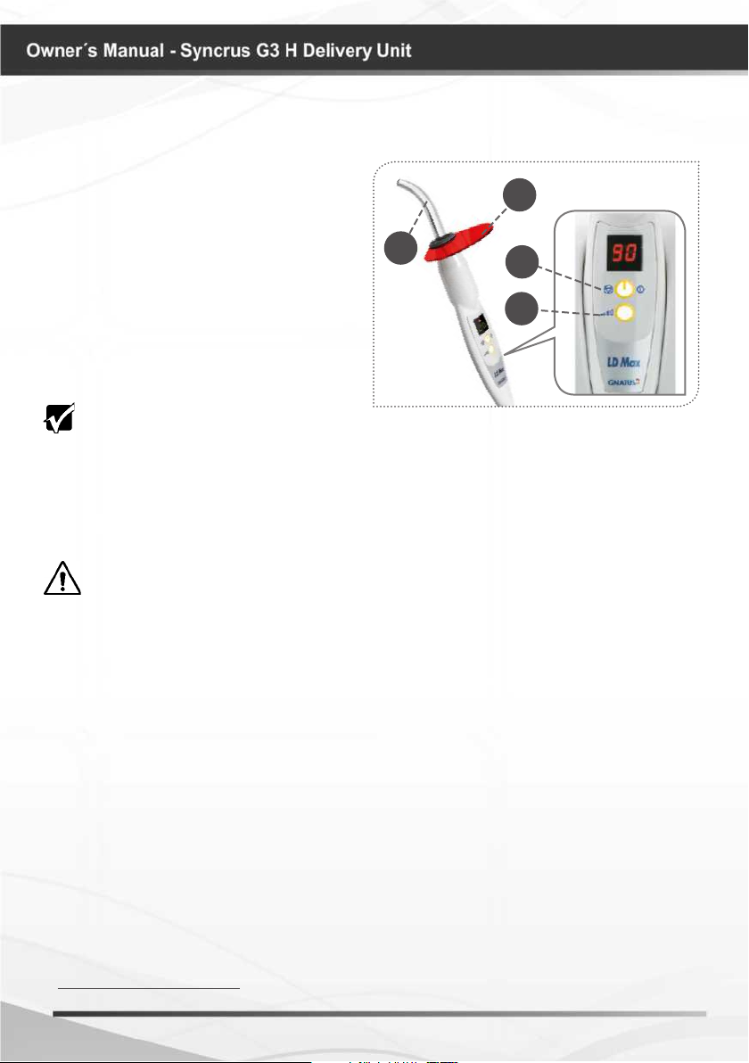
Curing Light Activation*
Select application time, press time
selection button (01), which values are: 10s
(standard mode), 20s, 60s, 80s and 90s.
To initiate a polymerization cycle, press the
timer trigger (02), which generates a short
beep every 10 seconds and a 4 beeps at the
end of cycle.
To interrupt a polymerization cycle just
activate the timer trigger again (02).
IMPORTANT:
Keep the light conductor tip (03) at least 2mm away from the restoration.
Keep the light conductor (03) always protected by an expendable PVC lm, which must
be changed for every patient. This procedure protects the light conductor from scratches
and other residues.
Use the polymerization time recommended by the compound resin manufacturer and
always perform restorations in incremental layers with a maximum thickness of 2mm.
WARNING:
Never aim the blue light beam towards the eyes.
Use the eyesight protection (04).
In order to protect the eyes, the eyesight protection (04) lters only the blue light used
for the resins polimerization, and it allows ambient light to pass through.
03
04
06
02
01
* Optional
22

OPERATION OF EQUIPMENT
Ultrasound Activation*
Remove the ultrasound hand piece from the holder;
Choose the appropriate insert for the wanted operation according to "Techniques and
Applications";
Screw the chosen insert in the hand piece with the aid of clamping key (01) and a small grip;
Actuate one of the pedals, progressive (Figure 1) * with water progressive locking
system of the hand pieces (g.2) * or chip-blower (g.3) * (models of the pedals can vary
according to the product conguration).
Place the selector power (C) in accordance with the sensitivity of operation.
Adjust the water ow through the record (D) located at the inferior part of the equipo.
At the end of the procedure release the lever from the pedal and place the hand piece
in the holder.
01
Feature available at the side panel when the
equipment conguration includes ultrasound.
C
Fig.1
Fig.2
Fig.3
D
C
D
Do not allow the hand piece with
A
IMPORTANT RECOMMENDATION
The shape and the weight of each insert are important facts to obtain a maximum
performance of the generator of ultrasounds, the operator attention to these two
insert to remain on the bit support
in order to avoid accidents.
* Optional
2323

OPERATION OF EQUIPMENT
characteristics, will assure the maintenance of the best performances of the units, however,
we recommended that the structure of the insert is not altered (limiting it or twisting it), in
the same way the aging of an inserted drives to an alteration of its original characteristic,
becoming it ineffective.
Any insert that has been damaged by use or accidental impact should be changed.
Technical and applications
All the inserts of the Ultrasound have the particularity
of vibrating in an only plane (front vibrations to back, and
in the axis of the insert).
The lateral vibrations common to other destartarizators
don’t exit, the rectilinear displacement favors more precise
approach of the tooth and of the gum.
The enamel and the cement are protected of the inutile
shocks.
Inside of this main plane of vibration, the end of each
insert is driven by small vibratory movements.
To abtain the maximum performance ot the Ultrasound
the operator should pay attention to the specic vibrations
regulations of each insert.
Periodontics
Insert Nº G1* “Removal of supragengival calculus”
Tip NºG1 is used for lingual, buccal and approximal supragingival
scaling. Recommended for the removal of gross calculus.
Recommended power setting: 10-50%.
Insert Nº G2* “Removal of supragengival calculus”
Tip Nº G2 is used for lingual and buccal supragingival scaling.
Recommended for the removal of gross calculus.
Recommended power setting: 10-100%.
Insert Nº G10P* “Universal”
Tip Nº G10-P is used for lingual and buccal supragingival scaling.
It’s one of the most popular Tips and is recommended for the
removal of heavy calculus.
Recommended power setting: 10-70%.
Endodontia
Insert NºG120* “Removal of broken instruments”
Tip G-120 is a holder for les and instruments with a diameter of
0.8 mm. It can be used with implant tips and AP tips. A-120 has
an angle of 120°.
Recommended power setting: 10-50%.
* Optional
24
OPERATION OF EQUIPMENT
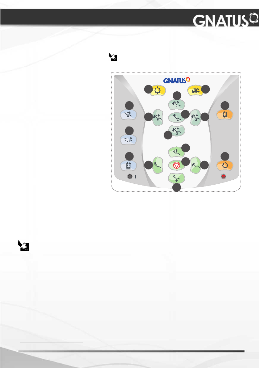
Equipment activation by the delivery unit panel*
Description:
01 - X ray view operation
02 - Activation of the dental light
03 - Initial position
04 - Work position “1”
05 - Work position “2”
06 - Work position “3”
07 - Work position “4”
08 - Spitting position / last position. de Cuspir
09 - Bowl’s water ow
10 - Cup lling copo
11 - Bio-System operation
12 - Emergency stop
13 - Rise seat
14 - Lower backrest
15 - Rise backrest
16 -Lower backrest
17 - Electric low-speed-motor
* *
rotation inverter
** Feature available at the control panel when the equipment is supplied with electric micro
motor in the conguration.
Warning:
To preset the cup lling time, press the “Cup lling” key (10) for 3 seconds (a long beep
will be heard and the LED will keep blinking).
When the desired time is reached, press the “Cup lling” key again. The cup lling time
is then set.
Control Panel:
The conguration of the equipment without the control
panel does not interfere with product operation.
01 02
04
08
09
05
06
03
07
11
13
10
15
12
16
17
14
The lling time of the glass is a consequence of water ow adjustment.
To preset the bowl’s water ow, pres the “Bowl water” key (09) for 3 seconds (a long
beep will be heard and the LED will keep blinking)
When the desired time is reached, press the “Bowl water” key again. The cup lling
time is then set.
The “Cup lling” and “Bowl water” time functions have a limited preset ow time, 1
minute for the cup lling and 1 minute for the bowl’s water ow.
When the key “Last position/Spitting position” (08) is pressed, the dental light will go
off (if it was on), the bowl will drain (for the preset time, and if it was not programmed yet,
for one minutes) and the backrest will go up to the spitting position. When pressed again,
the backrest will return to the last position and the dental light will go on (if it was on).
After pressing the “Last position/spitting position” key (08), any other operation will
trigger the “Stop”, and automatically the backrest current position will be dened as “Last
position”.
* Optional
2525
OPERATION OF EQUIPMENT
When the “Emergency stop” (12) key is pressed, the LED will be on and all chair
movements are interrupted until pressed again (12).
It has 4 programmable working positions. To program, just position the chair and the
reector at the desired intensity and keep the chosen working position key pressed for
3 seconds, the chair will produce a long bip determining that the position was already
programmed.
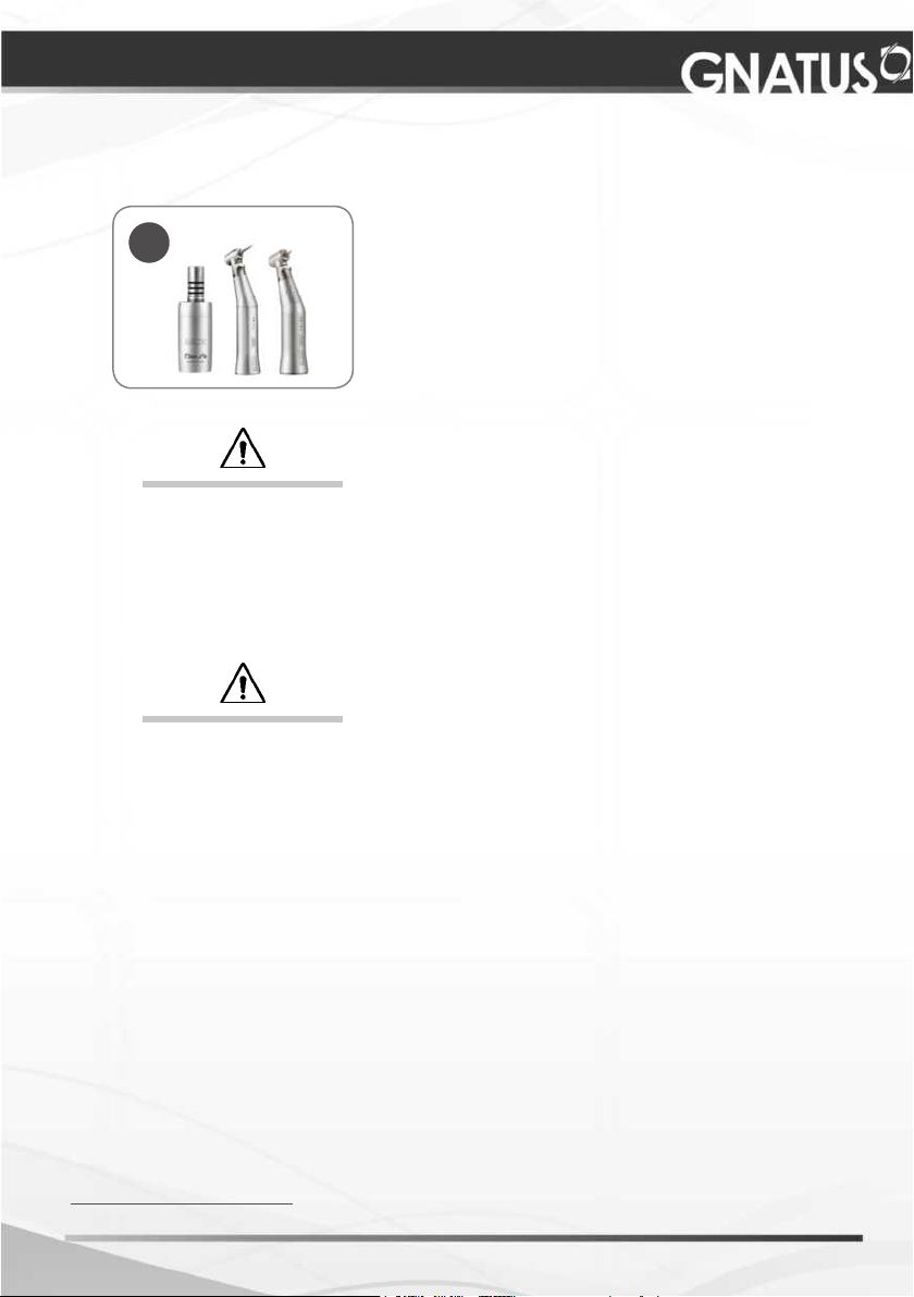
Use and applications (Digital control panel kit*)
To turn on the “Optima MX2”, just take out the electric micromotor
terminal from the support (A) where it is coupled and chose the
operation option:
- Operative (contra angle 1:5);
- Endo (contra angle 1:1).
To turn off, put back the terminal to the equipment’s support (B).
* Optional
A
B
OFF
Micromotor lever in
initial position.
- Digital control panel with rotation system;
- High torque micromotor;
- Contra angle 1:1;
- Contra angle 1:5;
- Allows reduction of the number of instruments.
It is possible to cover most operations with only two contra angles;
- Wide speed range
(100 to 40.000 rpm with CA 1:1 and 500 to 200.000 rpm with CA 1:5);
- Maintains constant selected speed;
- 40 programs available (20 preset).
26
ON
Micromotor lever
turned to the front.

OPERATION OF EQUIPMENT
How to provision the reservoirs
Water - Syringe / Handpieces
Remove the reservoir (01) uncoiling it on clockwise and make the replacement of water.
After the replacement put it back coiling on anticlockwise. Always use ltered water or
aseptic products.
Bio-System*
Remove the reservoir (02) uncoiling it on
clockwise and make the replacement. Use a
chlorinated water solution 1:500
Preparing the solution:
From a solution of hypochlorite of sodium at 1%,
a solution of chlorine at 500 p.p.m. is prepared.
How to prepare the solution: Take 25ml of
hypochlorite of sodium at 1% and dilute it in 500 ml
of water (1 to 20). Such solution should be prepared
daily.
IMPORTANT:
Follow this proportion strictly to avoid damages
in the equipment and to have an efcient result in
the disinfection.
Supply through the Water Unit
Bio-System*
Remove hanpieces from terminals. Take terminals to
bowl or water unit’s sink.
Open the terminal’s spray valves completelly.
Press the Bio-system key, which is located in the
command panel, for some seconds, to disinfect the
equipment’s components internally with disinfectant.
Then, press the command pedal for some seconds to
rinse, in order to eliminate the disinfectant residues that
could have remained.
01
02
IMPORTANT:
Repeat this procedure before working day and after each patient.
Bicarbonate Jet "Jet Hand"*
Refer to Owner's Manual of Jet Hand (available for viewing and downloading via www.
gnatus.com.br/manuais)
* Optional
2727
PRECAUTIONS, RESTRICTIONS AND WARNINGS
Transportation, storage and operation
This equipment must be transported and stored observing the following directions:
- Avoid falls and impacts;
- Keep it dry, do not expose it to rain, water drops or wet oor;
- Keep it away from water and direct sunlight, and in it original wrapping;
- Don’t move it over irregular surfaces, protect it from rain and observe the maximum
stack quantity specied in the packaging;
- Transportation and storage temperature range: -12°C to 50°C.
- Ambient temperature range recommended by Gnatus +10 ° C to +35 ° C.
The Equipment maintains its condition of safety and efcacy, provided that it is
maintained (stored) as mentioned in this instruction of use. Thus, the equipment
will not lose or alter its physical and dimensional features.
Sensitivity to environmental conditions in normal situations of use
The equipment has been planned not to be sensitive to interference such as magnetic
elds, external electrical factors, electrostatic discharge, pressure or variance of pressure,
provided that the equipment is installed, maintained, clean, preserved, transported and
operated as per this instruction for use.
The equipment must not be used in proximity to, or stacked with other equipment. If
the use in proximity or stacking is necessary, the equipment operation should be assessed
to verify that it works normally in the conguration in which it will be used.
Precautions and warnings “during the installation” of equipment
- The equipment should only be installed by Gnatus authorized technical assistance or
technicians.
- Position the unit in a place where it will not get wet.
- Install the unit in a place where it will not be damaged by the pressure, temperature,
humidity, direct sunlight, dust, salts, or sulfur compounds.
- The unit should not be submitted to inclination, excessive vibrations, or blows (including
during transportation and handling).
- This equipment was not planned for use in an environment where vapors, anesthetic
mixtures inammable with air, or oxygen and nitrous oxide can be detected.
- Before the rst use and/or after long interruptions from work such as vacations, clean
and disinfect the equipment; eliminate air and water deposited in the internal hoses.
These information also make part of the Manual of Installation and
Maintenance of the equipment that can be found with the authorized
Gnatus technician.
28

PRECAUTIONS, RESTRICTIONS AND WARNINGS
Recommendations for the dental equipment maintenance
Your Gnatus equipment has been designed and developed according to the standards
of modern techology. Similarly to other kinds of equipment, it requires special care, which
is many times neglected due to several reasons and circunstances.
Therefore, here are some important reminders for your daily routine. Try to follow these
simple rules, which will save you a lot of time and will avoid unnecessary expenses once
they start making part of your working procedure.
Precautions and warnings “during the use” of equipment
- The equipment should only be operated by duly enabled and trained technicians (Dental
Surgeons, Capacitated Professionals)
- If any maintenance should be required, only use services of the Gnatus Authorized
Technical Assistance.
- The equipment has been manufactured to handle both continuous and intermittent
operation; so follow the cycles described in these Instructions for Use.
- Although this equipment has been planned in accordance with the standards of
electromagnetic compatibility, it can, in very extreme conditions, cause interference with
other equipment. Do not use this equipment together with other devices very sensitive to
interference or with devices which create high electromagnetic disturbance.
- Do not expose the plastic parts to contact with chemical substances, use in the routines
of dental treatment, such as: acids, mercury, acrylic liquids, amalgams, etc.
- Avoid the light conductor terminal touch with the resin to be polymerized.
- While using the Curing Light verify that the output of the light pen has no residues that may
obstruct the light beam.
Bicarbonate Jet:
- It is not advisable to use this equipment in patients who have serious renal or respiratory
alterations, or who undergo hemodialysis. These cases should be followed be followed by
a doctor.
- We recommend the use of a mask and goggles for applying the bicarbonate jet.
- Avoid leaving sodium bicarbonate in the container for long periods without use.
The effect of residual humidity in the air may alter the properties of the powder and
cause blocking.
Gnatus shall not be responsible for:
- Use of the equipment differing from that for which it is intended.
- Damages caused to the equipment, the professional and/or the patient by the incorrect
installation and erroneous procedures of maintenance, differing from those described in
these Instructions for use which come with the equipment or by the incorrect operation of it.
Precautions and warnings “after” the use of equipment
- Turn off the main switch of the dental set when it is not in use for an extended period
of time.
- Always maintain the equipment clean for the next operation.
- Do not modify any part of the equipment. Do not disconnect the cable or other
connections without need.
- After using the equipment, clean and disinfect all the parts which may be in contact
with the patient.
- Upon noticing irremovable stains, splits or cracks in the light conductor or in the eye
protector, replace the damaged components.
2929

PRECAUTIONS, RESTRICTIONS AND WARNINGS
Precautions and warnings during the “cleaning and disinfection”
of equipment
Delivery Unit:
- Before cleaning the equipment, turn off the main switch.
- Avoid spilling water, even accidentally, or other liquids inside the equipment, which
could cause short circuits.
- Do not use microabrasive material or steel wool when cleaning, or employ organic
solvents or detergents which contain solvents such as ether, stain remover, etc.
Curring Light:
- The equipment and the light conductor cannot be placed in the oven or autoclaves.
- The conductor can’t be immersed in solvents or substances that contain acetone in its
composition.
Ultrasound:
- After use, remove the insert to avoid damage.
- The part should be packaged duly clean.
- Do not sterilize the transducer in contact with other types of material.
- The inserts should be cleaned beforehand eliminating all the resin residue.
- After removing the insert from the transducer, it should be disinfected with surgical
spirit and taken to be sterilized in autoclave.
Bicarbonate Jet:
Refer to Owner's Manual of Jet Hand (available for viewing and downloading via www.
gnatus.com.br/manuais)
Precautions in case of alteration in the functioning of equipment
- If the equipment has any abnormality, check if the problem is related to any item
listed in the topic of unforeseen events (failures, causes and solutions). If it is not possible
to resolve the problem, turn off the equipment, remove the power supply cable from the
socket and contact your representative (Gnatus).
Precautions to be adopted against foreseeable or uncommon
risks, related to the deactivation and abandoning of equipment
In order to avoid environmental contamination or undue use of the Equipment after it
has become useless, it should be discarded in the suitable place (as per the local legislation
of the country).
- Pay attention to the local legislation of the country for the conditions of installation
and disposal of residue.
30
CORRECTIVE AND PREVENTIVE MAINTENANCE AND
PRESERVATION
Additional procedures for reuse
The equipment can be reused in undetermined, i.e. unlimited, quantities, only needing
to be cleaned and disinfected.
Cleaning
Important: In order to execute cleaning or any type of maintenance, ensure that the
equipment is disconnected from the electrical network.
The cleaning procedure below should be executed at the start of the
working day and after each patient.
Always turn off the main switch before executing the procedures of
daily maintenance.
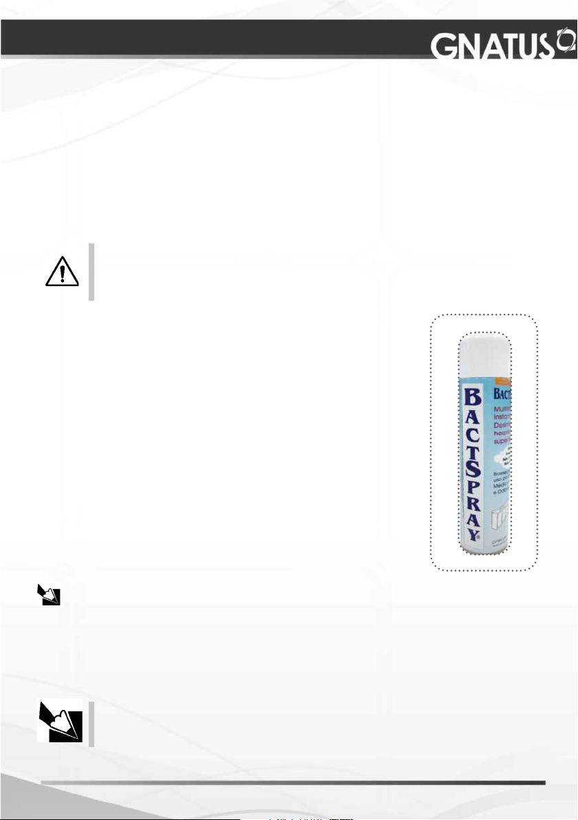
To clean the equipment, we recommend the use of “BactSpray
(Reg nº MS: 3.2079.0041.001-5) or any other similar product:
Active component: Benzalkonium chloride (tri-quaternary
ammonium)
Solution 50%................................................. 0.329%
Chemical composition: Butyl Glycol, Decyl polyglucose, Sodium
Benzoate, Sodium Nitrate, Essence, Deodorized Propane / Butane,
demineralized Water.
For more information concerning cleaning procedures, see
manufacturer’s instructions.
WARNING:
- This product can also be used for cleaning and disinfection of
the water basin unit.
- In order to prevent risks and damages to equipment, make sure
that the liquid does not enter into the unit.
- The application of other solvent-based cleaning products or
sodium hypochloride isn’t recommended, because they may damage
the equipment.
NOTE: The registration at the Ministry of Health of the “BactSpray” is executed
separately from the product described in this manual, as the “BactSpray” is not
manufactured by Gnatus.
Disinfection
Use clean and soft cloth dampened in alcohol 70% to disinfection of the equipment.
Never use corrosive disinfectants or solvents.
Note: Use gloves and other
systems of protection,
during the disinfection.
3131

CORRECTIVE AND PREVENTIVE MAINTENANCE AND
PRESERVATION
Curring Light
The light conductor cleaning and the optical protector must be done using only neutral
soap and cotton. To the exterior of the pen use neutral soap or alcohol 70% vol.
Never use any other chemical based product than previous mentioned, because along
the time these products attack the surface of the instrument.
Never immerse the instrument in disinfection baths.
Ultrasound
The device is reusable in unspecied quantities, ie endless, only requiring cleaning and
disinfecting.
Cleaning of terminal, transductor cover and hose:
We recommend using a clean cloth, dampened with water and mild soap.
Autoclavable:
Transducer-Cover, inserts and key are autoclavable under the following conditions:
- Maximum temperature of 134 º C.
02
Transducer cover sterilization:
Remove the insert from the transducer.
Carefully remove the cover (01) from the transducer (02)
then take it to autoclaving (packed).
Recommendations for autoclave sterilization:
- The piece must be properly packed clean.
- Do not sterilize the transducer cover in contact with other materials.
- The inserts must be cleaned earlier eliminating all resin residues.
- After removing the insert from the transducer, it should be disinfected with surgical alcohol
and taken to autoclave for sterilization.
- The material of the transducer cover was developed to support up to 200 cycles of
autoclaving, provided the recommendations are done according to stated above.
CAUTION: Never expose the transducer covers to any type of oil because it can modify the
structure of the material compromising it´s useful life.
01
Bicarbonate Jet "Jet Hand"
Refer to Owner's Manual of Jet Hand (available for viewing and downloading via www.
gnatus.com.br/manuais)
32
CORRECTIVE AND PREVENTIVE MAINTENANCE AND
PRESERVATION
Reservoirs
It’s highly recommended the cleaning of the water reservoirs, using chlorinated water
solution 1:500.
Triple syringe
Only the syringe tip is autoclavable (01). The other pieces
must be cleaned using a piece of cotton wool and alcohol
70% vol. Never use a hot air sterilizer.
01
02
Tips support
To remove tips support from equipment, just
pull it, as shown in gure.
To clean tips support (02) use water and neutral
soap. To sterilize in autoclave, use a 134°C
cycle. The tips support was designed to stand
more than 200 autoclave cycles.
Preventive Maintenance
The equipment must suffer routinely measurements, following the current legislation
of the country.
But, never with a period superior to 3 years.
For protecting your equipment, look for a Gnatus’ technical assistance for periodic reviews
as preventive maintenances.
Corrective Maintenance
Gnatus states that the supplying of the circuits’ diagram, Part lists or any other information
that permits the technical assistance by the user, can be requested, since previously agreed
between the buyer and Gnatus.
In case of the equipment presents any abnormality; check if the problem is related
to some of the listed items under the item Unpredictable (situation, cause and
solution). If it’s not possible to solve the problem, shutdown the equipment and call
Gnatus’ technical assistance.
3333

UNFORESEEN EVENTS – SOLUTION OF PROBLEMS
Upon coming across any problem in operation, follow the instructions below to
check and repair the problem, and/or get in touch with your representative.
Problem Probable cause Solution
Delivery Unit
-Handpiece is not working. - Compressor disconnected. -Plug the compressor in.
-Handpiece with low speed. -Inlet pressure below speci-
-No water from handpiece
spray.
-No water from syringe. -Reservoir run out of water.
-When Bio-system is operated no disinfectant come
from handpiece terminals.
- X ray view does not
work
Curring Light
-Equipment’s not working.
ed (80 PSI).
- Insufficient air pressure
from compressor.
-Reservoir run out of water.
-Closed terminal.
-Compressor disconnected.
-Bio-system reservoir run
out of water.
- Chair fuse burned.
-Main or chair switch is off
-Chair’s fuse burned.
-Main switch is off.
-Power cut.
-Chair’s fuse burned.
-Adjust inlet pressure (80
PSI).
-Adjust air ow.
- Put ltered water in reser-
voir.
- Open terminal.
-Put ltered water in reservoir.
-Plug compressor in.
-Put disinfectant in the reservoir.
- Turn off the chair from
mains power and request a
Technician presence.
-Switch main/chair switch
on.
-Turn off the chair from
mains power and request a
Technician presence.
-Switch the main switch on.
-Check power supply.
-Turn off the chair from mains
power and request a Technician presence.
-Equipment is not polymerizing resins.
-Resin is not appropriate
for LED’s photopolymerizer
wave length range.
- Resin residues in light
cable.
34
-Get the indicated resin for
the photopolymerizer’s wave
length range, one with contains photoinitiators based
on camphorquinone.
-Clean the light cable.

UNFORESEEN EVENTS – SOLUTION OF PROBLEMS
Upon coming across any problem in operation, follow the instructions below to
check and repair the problem, and/or get in touch with your representative.
Problem Probable cause Solution
Ultrasound
-The equipment doesn’t
work.
-Lack of power to the ultrasound.
-Chair’s fuse burned -Turn off the chair from mains
- Deformed insert.
- Loosen insert.
- Bad utilization (incorrect
attack angle).
power and request a Technician presence.
- Change the insert.
- Hold the insert with the key
- See item “Technical and
applications”.
-There is no water in the
hand piece.
Bicarbonate Jet - For further information, please see the Bicarbonate Jet
- Inadequate alimentacion
pressure water.
- Bad regulating of the water
ux.
"Jet Hand" manual which comes with the product.
- Correct the water lter.
- Adjust the water ux throu-
gh the actuator.
3535

EQUIPMENT’S WARRANTY
This equipment is covered by the warranty terms and norms contained in the Warranty
Certicate that accompany the product.
FINAL CONSIDERATIONS
Among the care you have to take with your equipment, the most important is regarding of
the spare parts replacement.
To ensure the lifetime of your device, only replace original spare parts from Gnatus. They have
the assurance of the standards and technical specications required by the Gnatus representative.
We call your attention to our authorized resellers’ chain. Only this chain will keep your
equipment constantly new, because it has trained technical assistant and specic tools for the
correct maintenance of your device.
Whenever you need, demand the presence of a Gnatus’ technician from the nearest resale,
or ask through the Attendance Service GNATUS: + 55 (16) 2102-5000 / SAC: 0800-7015-054.
36

3737

38

3939

 Loading...