

GMX MOTORBIKES GMX 125 SPORTZILLA X User Manual

Read and understand this entire manual before riding!
DO NOT RETURN TO STORE!
WWW.GMXMOTORBIKES.COM.AU
NOTE: Manual illustrations are for demonstration purposes only. Illustrations man not reflect exact appearance of actual product.
ATV OFF ROAD - GMX 125 SPORTZILLA X
RIDE SAFE
- Never let children ride quad bikes that are meant for adults – even as passengers.
- Do not carry any passengers on quad bikes that are meant for one person.
- Quad bikes are not all-terrain vehicles so they cannot go safely on all types of terrain. Avoid riding on rough terrain or steep slopes.
- Ride on familiar tracks and beware of obstacles.
- Never ride under the inuence of alcohol/drugs.
- Ensure children are supervised at all times near any quad bike activity.
- Always carry a mobile phone or radio device so you can contact help in case of an emergency.
WEAR SAFE
- Always wear a helmet.
- Wear protective clothing and gear such as goggles, long sleeves, long pants, boots and gloves/hand protection.
Ensure that you understand your quad bike by reading & going over the manual before assembly.
YOU MUST CHECK
THAT THE FRONT
STEERING IS ADJUSTED
CORRECTLY PRIOR
TO RIDING.
CHECK BRAKES
ARE ADJUSTED
CORRECTLY PRIOR
TO RIDING.
YOU MUST CHECK
THAT THE CHAIN
IS ADJUSTED
CORRECTLY PRIOR
TO RIDING.
PLEASE READ AND UNDERSTAND ALL INSTRUCTIONS AND WARNINGS PRIOR TO ASSEMBLY AND OPERATING OF YOUR VEHICLE.
Swing tags have been placed on your vehicle for you to identify checks that are located within this manual. Once you have performed the
check required remove these swing tags and nylon loops attaching them to the vehicle.
MAKE SURE TO REMOVE THE SWING TAGS AND TAKE SPECIAL NOTICE TO REMOVE THE NYLON LOOP.
The tags and loops that need to be removed from this model: GMX 125cc Sportzilla X Quad Bike
ONCE SWING TAGS AND NYLON LOOPS ARE REMOVED YOU ARE ACKNOWLEDGING THAT THESE
CHECKS HAVE BEEN PERFORMED
There may be a “Spare Parts Package” within the carton so please check all of the packaging
and DO NOT THROW OUT
WARNINGS
SWING TAG’S & WARNINGS
BRAKE ADJUSTMENT x3STEERING ADJUSTMENT x2 CHAIN ADJUSTMENT
ALWAYS LEAVE IN
THE OFF POSITION
WHEN NOT IN USE
OR REMOVE KEYS
KEY REMOVAL
WARNING
Please use unleaded fuel
90 Octane or above
UNLEADED FUEL ONLY
WARNING: This product is powered by a 4 stroke engine and comes with transport oil in the engine.
THE OIL NEEDS TO BE DRAINED AND REPLACED WITH MOTORCYCLE OIL 10W/40 or 10W/50 IS REQUIRED
IF THE OIL CHANGE IS NOT PERFORMED YOU MAY INTERNALLY DAMAGE THE ENGINE AND CLUTCH AND VOID YOUR WARRANTY
DO NOT USE MOTOR CAR OIL
DO NOT USE OIL WITH FRICTION MODIFIERS
OIL WILL NEED TO BE CHANGED EVERY 3 MONTHS IN A HOTTER CLIMATE OR THE NOTHERN HEMISPHERE
- There is an oil drain plug located underneath you quad/dirt bike and is highlighted with an oil drain plug sticker. This is a 14mm bolt.
- DO NOT remove the other bolt located under the engine.
- Place an oil receptacle under the drain hole, undo bolt and let oil drain from the vehicle. Please note: Dispose of oil correctly
- Tighten bolt back up, remove dipstick (oil ll point) and ll the vehicle with suggested correct amount of oil required. Tighten
TO AVOID DAMAGE TO GEARBOX AND
MOTOR. WHEN SELECTING GEAR AND
CHANGING GEARS, RELEASE THE
THROTTLE. DO NOT USE EXCESSIVE
FORCE ON GEAR LEVER.
GEAR LEVER
GMX MOTORBIKES WARRANTY
Our goods come with guarantees that cannot be excluded under the Australian Consumer Law. You are entitled to a replacement or refund for a major
failure and compensation for any other reasonably foreseeable loss or damage. You are also entitled to have the goods repaired or replaced if the goods
fail to be of acceptable quality and the failure does not amount to a major failure.
The manufacturer warrants this product to be free of manufacturing defects for a period of 12 months from date of purchase. This Limited Warranty does
not cover normal wear and tear (exclusions apply) or any damage, failure or loss caused by improper assembly, maintenance or storage or use of the GMX
product. Some parts will have a limited warranty period, please see below. This warranty is a part replacement warranty.
3 Month Parts Replacement Parts
Electrical components, suspension, drivetrain and brakes/ttings.
30 Days Parts Replacement Parts
Bearings, tires, tubes, cables, clutches, brake pads, seats.
Minor assembly is required. In the interest of safety and future warranty claims, it is recommended that you have this product assembled by a qualied, skilled
motorcycle mechanic.
You may need to provide proof for this product of being assembled by a skilled motorcycle mechanic or small engine mechanic a report dvising of the issues may
be needed to process your warranty claims.
The warranty is a parts replacement warranty and labor is not included, defective parts may need to be sent back for inspection.
This Limited Warranty will be void if the product is ever;
- Used in a manner other than for recreation.
- Modied in anyway.
- Rented or commercial use.
The manufacturer is not liable for incidental or consequential loss or damage due directly or indirectly misuse of this product.
Always adhere to the maximum load of the product, over loading the product will void the warranty.
How a claim is made
When making a claim, you will need to provide proof of purchase, condition photos of the item. This information is required to be submitted via the
support center and communication is made through the support center. When the claim is created, the customer will receive the claim number and the
customer support team will reply within 24 hours.

SAFETY PRECAUTIONS
RIDING PRACTICES
ASSEMBLY
HANDLEBARS .3
FRONT END .4
BRAKES CHECK .5
BRAKE HOSES .5
FRONT WHEELS .6
REAR WHEELS .6
REAR WHEELS .7
FRONT BUMPER BAR .7
REAR FOOTWELLS .8
REAR FOOTWELLS .9
STEERING ALIGNMENT .9
CONNECTING BATTERY .10
CHECKING OIL IN ENGINE .10
CHECK OVER BIKE .10
GOVERNOR CHECK .11
STARTING .11
START USING YOUR GMX BIKE .11
.1
.2
TROUBLE SHOOTING .12/13
CONTENT
1.
Turn o
ASSEMBLY
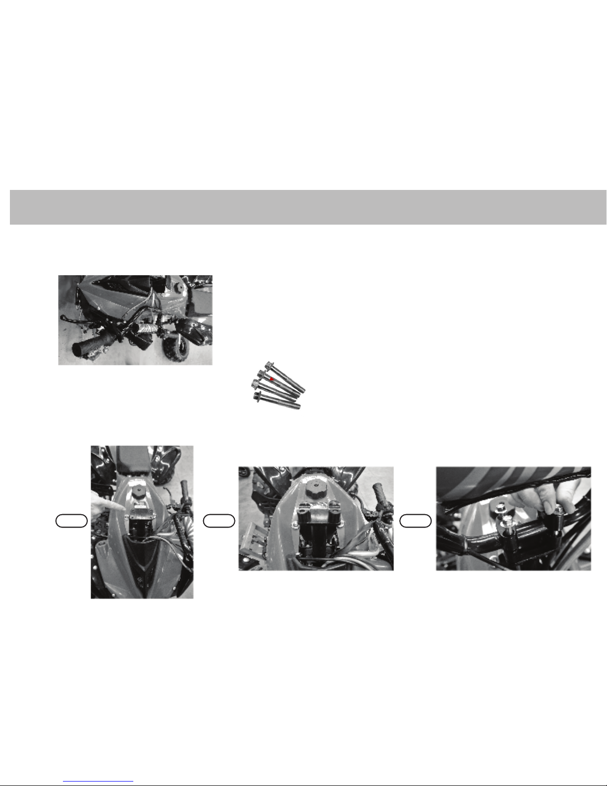
HANDLEBARS
1a. Handlebars are found generally on the side of the quad attached by the cables.
1b. Locate 4x handlebar xtures and bolts in pack.
1c. Place two of the xtures on the on top of the steering column lining up with the bolt holes, place handlebars on top, then the
two remaining xtures then bolt down and tighten.
STEP .1 STEP .2 STEP .3
*TIP: Be careful not to pinch cables
3.
ASSEMBLY
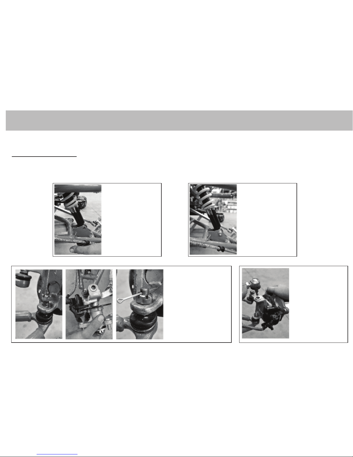
FRONT END
Front Suspension and Steering
Before installing please make sure all wheel are at the correct tyre pressure which is located on the wall of the tyre.
Lift bottom swing arm
into place at bottom of
shock absorber.
Insert bolt and attach
swing arm to shock
with bolt and nut
provided, tighten bolt
and nut.
Place lower front axle
steering bracket on lower
ball joint and fasten with
small castle nut, tighten
castle nut and insert split
and bend around castle nut.
THIS WILL BE REQUIRED ON BOTH SIDES LEFT AND RIGHT.
Place upper front axle
steering bracket on
upper ball joint and
fasten with small
castle nut, tighten
castle nut and insert
split and bend around
castle nut
1. 2.
3. 4.
4.
 Loading...