


TG uni 1
Appliance tester for
testing safety measures in accordance
with DIN VDE 0701and 0702
Operating Manual
Version 1.07

Operating manual for the TG uni 1 appliance tester
Contents
Contents Page
1. Safety information ..........................................................4
2. Introduction .......................................................................4
2.1 Model and type designation / identification ...............................5
2.2 Product description ................................................................5
2.3 Other equipment features ...................................................5
2.4 Scope of delivery ....................................................................5
2.5 Optional accessories ...............................................................5
2.6 Transport and storage .............................................................5
3. Safety instructions ...............................................................6
4. Appropriate usage ..........................................................7
5. Operating elements ...............................................................8
5.1 Meaning of the signal tones .........................................................8
6. Commissioning ...............................................................9
6.1 Basic settings of the tester ...................................................9
6.2 Compensation of the measuring line ..........................................10
6.3 Setting the measuring method for
protective conductor current measurement ..................................10
6.4 Setting the date ............................................................11
6.5 Selection of the data memory ....................................................11
6.6 Changing the duration of a test stage ............................................12
6.7 Entering the name of the inspector ..............................................12
6.8 Customer-specific settings ...............................................12
7. Conducting tests:
General information on
DIN VDE 0701 and DIN VDE 0702 ...........................................13
7.1 Why ..................................................................................13
7.2 What ...............................................................................13
7.3 How ...............................................................................13
Contents Page
8. Conducting tests:
Explanation of terminology ....................................................14
8.1 Touch current (IT) ..................................................................14
8.2 Differential current (ID)............................................................14
8.3 Substitute leakage current (ISL) .....................................................14
8.4 Insulation resistance (R
8.5 Protection class I (PC I) ...............................................................15
) ..........................................................15
INS
8.6 Protection class II (PC II)..............................................................15
8.7 Protection class III (PC III) ............................................................15
8.8 Protective conductor current (IPE) ...................................................16
8.9 Protective conductor resistance (RPE) ............................................16
8.10 Visual inspection .......................................................................16
9. Conducting tests in accordance with
DIN VDE 0701 and DIN VDE 0702:
Definition of standards ...........................................................17
9.1 Visual inspection .......................................................................17
9.2 Measuring the protective conductor resistance ................................17
9.3 Measuring insulation resistance ............................................17
9.4a Measuring the protective conductor current ....................................18
9.4b Measuring touch current ................................................19
9.5 Inspecting the inscriptions ............................................................19
9.6 Function test ......................................................................19
9.7 Documentation ..........................................................................19
9.8 Diagram 1:
Test procedure for devices of protection class I ................................20
9.9 Diagram 2:
Test procedure for devices of protection classes II und III ...................21
2

Operating manual for the TG uni 1 appliance tester
Contents
Contents Page
10. Conducting tests with the appliance tester in accordance
with DIN VDE 0701 and DIN VDE 0702, PC I .........................22
10.1 Visual inspection .......................................................................23
10.2 Protective conductor resistance ....................................................23
10.3 Insulation resistance ..................................................................24
10.4a Protective conductor current (substitute leakage current) ...................25
10.4b Protective conductor current ........................................................25
10.5 Function test ......................................................................26
10.6 Inspecting the inscriptions ............................................................26
10.7 Documentation ..........................................................................27
11. Conducting tests with the appliance tester in accordance
with DIN VDE 0701 and DIN VDE 0702, PC II ........................29
11.1 Visual inspection .......................................................................30
11.2 Insulation resistance ..................................................................30
11.3a Touch current (substitute leakage current) .......................................31
11.3b Tou ch current ......................................................................31
11.4 Function test ......................................................................32
11.5 Inspecting the inscriptions ...........................................................32
11.6 Documentation ..........................................................................33
12. Conducting tests with the appliance tester in accordance
with DIN VDE 0701 and DIN VDE 0702, PC III .......................35
12.1 Visual inspection .......................................................................36
12.2 Insulation resistance ..................................................................36
12.3 Documentation ..........................................................................37
13. Conducting tests with the appliance tester in accordance
with DIN VDE 0702, all protection classes ...........................39
14. Conducting tests with the appliance tester in accordance
with DIN VDE 0701 and DIN VDE 0702 - special test procedure
according to customer-specific settings..............................40
Contents Page
15. Technical data ....................................................................42
15.1 Technical data for function tests ..........................................43
15.2 General technial data ........................................................43
16. Manifacturer’s guarantee conditions ........................................44
3

Operating manual for the TG uni 1 appliance tester
Safety information
1. Safety information
Tests on the electrical safety of electrical appliances may only be carried
out by qualified electricians or under their supervision. Carefully read the
following safety information before commissioning the TG uni 1 appliance
tester (referred to as appliance tester or tester in the following).
Symbols used in the operating manual and on the tester:
Warning:hazardous situation. Follow the operating manual.
Caution! Dangerous voltage, danger of electric shock.
Note. Make sure you follow the manual.
&&
&
&&
CE CE mark of conformity.
The operating manual contains information and notes which are
&&
&
&&
necessary for the safe operation and use of the tester. Before use
(commissioning / installation) of the tester the operating manual
should be carefully read through and followed in all points.
If the manual is not observed or if you fail to observe the warnings
&&
&
&&
and notes, serious injury to the user and damage to the tester can
occur.
All the technical data and quoted standards in this manual are up-
&&
&
&&
to-date at the time of going to press and have been determined to
the best of our knowledge, nevertheless this data may be subject
to errors and printing errors. Therefore no legal responsibility or
any other liability can be accepted for incorrect information or
the conseqences of this information.
The definitive document for carrying out tests is the
original version of the respective regulation or standard.
There is no intention to
other property rights with this publication.
2. Introduction
You have acquired a high-grade device from the company Gossen Müller &
Weigert (GMW), with which you can carry out repeatable measurements
over a very long period of time. The product was calibrated during the
manufacturing process in accordance with the specified operating
procedures. All quality-relevant activities and processes carried out in GMW
are permanently monitored as part of the quality management system in
accordance with DIN EN ISO 9001:2000.
infringe on any existing patents and
4

Operating manual for the TG uni 1 appliance tester
Introduction
2.1 Model and type designation / identification
A type plate and serial number sticker are situated on the inside of the
housing cover (behind the accessories bag).In the case of queries, always
give the product designation and serial number.
2.2 Product description
The appliance tester has been developed for carrying out the following
measurements for testing the safety of electrical appliances in accordance
with DIN VDE 0701 and 0702 (BGV A3):
– Measuring protective conductor resistance with compensation of the
measuring line
– Measuring insulation resistance
– Measuring substitute leakage current
– Measuring protective conductor current (direct method or as differential
current)
– Measuring touch current
– Function test with measurement of mains voltage, load current, active
power, apparent power and reactive power, power factor and
frequency
– Testing of non-heating devices and extension cables
2.3 Other equipment features
– Stable, dust-proof carrying case as housing
– Large, easy-to-read touch-screen for operating the tester (backlit)
– Good/bad display in plain text (suitable for technically trained persons)
– Connection for barcode scanner for reading-in the test object’s ID
numbers
– USB-interface
– MMC-card for saving and transporting measured data
– PC standard software for saving and printing measurement reports
2.4 Scope of delivery
1 TG uni 1 appliance tester
1 safety test line, length 100 cm
1 safety crocodile clip, clip width 30 mm
1 safety test tip
1 USB cable, length 150 cm
1 MMC memory card 128 MB
1 CD-ROM with Windows®-PC standard software
1 accessories bag with velcro fastener and quick guide
1 operating manual
2.5 Optionale accessories
(not included in delivery)
– Barcode scanner
– RS232 PC interface cable, length 200 cm
– Measuring adapter for testing devices with tree-phase connection (in
preparation for plug connectors CEE 3-pole, 16 A, 230 V; CEE
5-pole, 16 A, 400 V and CEE 5-pole, 32 A, 400 V)
– Adapter for checking extension cables
– PC software with database functions (customer master data, device
master data, test data, analysis function, data backup)
2.6 Transport and Storage
Please retain the original packaging for dispatch at a later date, e.g. for
calibration. Transport damage that occurs due to inadequate packaging is
not covered by the manufacturer’s guarantee.
The tester must be stored in a dry, closed room. If the device it transported
in extreme tenperatures, it requires at least 2 hours acclimatisation before
being switched on.
5

Operating manual for the TG uni 1 appliance tester
Safety instructions
3. Safety instructions
The appliance tester TG uni 1 was constructed and tested in accordance
with the applicable safety regulations and left the workshop in a faultless
safety condition. In order to maintain this condition and ensure safe
operation, the user must observe the instructions and warnings contained in
this operating manual.
With all work, the applicable accidend prevention regulations of the
&&
&
&&
trade associations for electrical systems and equipment must be
observed.
To avoid electric shock, the applicable safety regulations and DIN-
VDE regulations regarding high touch voltage
without fail when working with voltages greater than 120V (60 V)
DC or 50 V (25 V) eff. AC. The values in brackets apply for
restricted areas (e.g. medicine, agriculture).
Measuring at a dangerous proximity to electrical systems should only be
carried out under the instruction of a responsible electrician, and never
alone.
Check the tester and the connecting cables for external damage before
every new operation.
Make sure that the tester and the connecting cables are in faultless
condition. The tester may not be used if one or more functions fail or if
functional readiness is not evident.
must be observed
The measuring lines and the measuring accessories may only be
touched in the designated handling areas.
Touching measuring connections, e.g. test tips must be avoided
under all circumstances.
If the safety of the operator is no longer guaranteed, the tester must
&&
&
&&
be decommissioned and secured against unwanted use. This is
the case if the device:
– shows obvious signs of damage
– no longer carries out the required measurements
– has been stored in adverse conditions for too long
The tester may only be used in the operating and measuring ranges
specified under Technical Data.
Prevent overheating of the tester by exposure to direct sunlight.
Only this will guarantee faultless functioning and a long sevice life of the
device.
Never open the housing of the tester because of the danger of high
voltages. The tester contains no parts that can be replaced by the user.
Only let the tester be serviced by qualified personnel.
6

Operating manual for the TG uni 1 appliance tester
Appropriate usage
4. Appropriate usage
The tester may only be used under the conditions and for the purposes for
which it has beeen designed. It is particularly important to observe the
safety instructions and the technical data regarding ambient conditions and
usage in a dry environment.
The tester may not be used for measurement in electrical systems.
The tester may only be plugged into a properly connected earthed mains
socket. This may be protected with a maximum 16 A!
The tester is designed for operation with a rated voltage of 230 V AC 50 Hz,
it may never be connected to higher voltage.
The maximum output current of the mains socket is 16 A!
The tester may not be used for constant measuring.
Operational safety is no longer guaranteed in the case of modifications or
conversions that have not been carried out by the manufacturer.
Maintenance or calibration work may only be carried out by the
manufcturer.
If the tester has been exposed to an electromagnetic field, this can impair
the functionality of the tester.
The tester may not be used near to explosive gasses, steam or dust, or in
a damp environment.
In order to avoid damaging the testing device, the test socket and the
measurement connections may not be connected to an external voltage
source.
Only the supplied original measuring lines or equivalent safety measuring
accessories may be used!
7

Operating manual for the TG uni 1 appliance tester
Operating elements
5. Operating elements
Explanation of the tetster’s connections, operating elements and displays
Mains cable with mains plug
for connecting the T ester to
the mains power supply
230 V +/-15%, 50 Hz
Thermal fuse for the test
object and tetster F 16 A
ON / OFF switch
Card slot for an MMC memory
card
USB socket for connecting a
PC
RS232 socket for
connecting a barcode
scanner
Storage compartment for the
mains cable
Housing cover with 2 snap fasteners
Accessories bag with quick guide
Case housing
Fig. 2
Handle (fold-away)
Test / mains socket for connecting the test object with earted
plug , 230 V 16 A, 50 Hz
Front panel, Fig. 1
5.1 Meaning of the signal tones
– short single tone: confirmation of button press
– short double tone: end of a test stage with automatic
– long single tone,
continuous tone: fault
8
Optional connecting sockets (VDE 0751):
´L1´ (black)
´N´ (blue)
´I
´ (red)
EPA
Connecting socket ‘PE’ (yellow/green), parallel
connection of the protective conductor of the
test socket, for connecting the test object
without an earthed mains plug
connecting socket ´Probe´ (red), for the test line
when measuring RPE and R
T ouch-screen (LC display and control screen)
Symbols used in the LC display:
- internal memory
- MMC memory card
INS
procedure

Operating manual for the TG uni 1 appliance Tester
Commissioning
6. Commissioning
The tester is equipped with modern touch-screen technology. That means
that the LC display and the control buttons are in one control screen. The
control buttons are always edged.
After activating the mains switch a self-test is carried out. If everything is in
order, the following display appears on the touch-screen as a switch-on
message (Fig. 3):
Fig. 3
Type designation
Relevant standard
Firmware version
Manufacturer
Large button
Continue with large button (Fig. 3).
A display for entering the date appears (Fig. 3a).
Fig. 3a
As the tester does not have its own real-time clock, you are prompted to
confirm the displayed date or enter a new date.
Also see Point 6.4.
&&
&
&&
After confirmation with the [OK] button the Main menue appears (Fig. 4):
Fig. 4
Headline
Function buttons:
T ests according to standard
T esting of individual parameters
Basic settings of the tester
6.1 Basic settings of the tester
Press the [Configuration] button in the Main menue (Fig. 4).
The Configuration menue appears (Fig. 5):
Headline
Fig. 5
Symbol for the internal memory
or the MMC memory card
Measuring method for protective
conductor or touch current:
DIR. - direct Measurement
(test object insulated from earth)
DIF. - differential current method
(Test object not insulated from
earth)
Function buttons
9

Operating manual for the TG uni 1 appliance tester
Commissioning
6.2 Compensation of the measuring line
In order to achieve correct results when measuring the protective conductor
resistance, the resistance of the measuring line must be compensated (zero
balance).
Press the fuction button [Comp.] (Fig. 5).
The zero balance menu appears. Follow the instructions in the display
(Fig. 6):
Fig. 6
– Connect the test tip/test
clip with the measuring line
and insert the measuring
line plug in the ‚Probe’
socket (Fig. 1).
– Connect the test tip/test
clip with the protective
earthing contact of the test
socket.
If the following message appears in the display:
‚Fault: zero balance’
and a permanent warning signal sounds, the measuring line resistance is
greater than 2 Ω and cannot be compensated.
The protective conductor resistance test is locked.
In this case the measuring line should be checked or be replaced with a
low-impedance version.
If the measuring line has been successfully compensated – the following
message appears in the display
‚Zero balance OK’.
Press the [Next] button, only then disconnect the line!
6.3 Setting the measurement method for protective conductor
current measurement (also current touch measurement)
In the case of devices of protection class I, on which the insulation
resistance measurement cannot or may not be carried out, the protective
conductor current measurement is an alternative measurement for
determining the insulating capacity.
The protective conductor current can be determined either by the direct
measuring method, the differential current method or the substitute leakage
current method.
The direct measuring method or the differential current method should be
used with test objects that can only be switched on with mains voltage
(also see Point 9.8).
Caution! In this case the test object is supplied with mains
voltage during the test.
The differential current measurement determines the total leakage current of
the test object by measuring the total current of all avtive conductors (L-N).
The differential current measurement must be applied if the test object has
additional earthing connections or cannot be insulated.
Direct measurement can be applied if the test object has no additional
earthing connections or can be insulated.
In order to change the measuring method, press the [Measure] function
button in the configuration menu, see Fig. 5.
The symbol in the headline changes accordingly:
[DIR.] – direct measurement
[DIF.] – differential current method
10

Operating manual for the TG uni 1 appliance Tester
Commissioning
6.4 Setting the date
You can set the test date on the tester.
Press the function button [Date] to change to the input screen (Fig. 5). The
date is entered on the touch-sreen by means of the pictured 10-button
keypad (Fig. 7).
The date can be entered in the following formats:
|D.M.YY|, |DD.MM.YY| and |DD.MM.YYYY|.
The set date is safed along with the measuring results of every test and
also appears in the log prinout.
Fig. 7
once the date has been set, it remains unchanged in the tester’s
&&
&
&&
memory until it is reentered or deleted
- the tester is not equipped with a real-time clock!
6.5 Selection of the data memory
To save the measurement results, the tester has an internal memory (16
MB) and an MMC memory card (128 MB, supplied with the tester).
The MMC memory card can be used to backup or transfer the
measurement results.
MMC memory cards with a capacity of 128 to 256 MB can be used.
Inserting the MMC memory card:
Insert the memory card, with the label facing down, into the card slot and
slightly press until it engages.
To eject the memory card, press it down until it disengages and pull the
card upwards and out of the slot.
Caution!
Never force the memory card into the card slot of the tester.
The use of force can damage the memory card and the card
slot. If the card is not recognised by the tester, check if it
has been properly inserted.
Press the function button [Memory] in the configuration menu to switch
between the internal memory and the MMC memory card. The symbol in
the headline changes accordingly (Fig. 5):
– internal memory
– MMC memory card
The measurement results can be stored either in the internal
&&
&
&&
memory or on the MMC memory card.
Use a PC with a USB connection if you wish to completely delete or format
the MMC memory card. After the USB connection has been made the MMC
memory card appears as an external storage medium in the file manager.
From here the card can be deleted or formatted – the file system is
automatically adjusted.
Caution! Formatting a memory card deletes all the data on the
card.
To read out saved measurement results - see the operating manual of the
PC software
11

Operating manual for the TG uni 1 appliance tester
Commissioning
6.6 Changing the duration of a test stage
With automatic test procedures, the preset duration of every test stage is 5
seconds.
This setting can be changed, if for example the test object requires a longer
time to be switched on.
To do this press the function button [T.-time] in the configuration menu.
Using the 10-button keypad, you can enter a new test time in the next
screen (Fig. 8).
The possible setting range is 3 to 254 seconds.
The factory setting of the tester is 5 seconds per test stage.
Fig. 8
6.7 Entering the name of the inspector
To enter the name or designation of the inspector, press the function button
[Inspector] in the configuration menu.
The screen changes to an alphanumeric keypad, with which you can enter
the name or the designation of the inspector. The input field has 20
characters (Fig. 9).
You can switch between letter and numeric keys by using the buttons [123]
or [ABC].
The [C] button deletes the last entered character.
Press the [OK] button to confirm the entry.
The entered name is saved in the memory after the tester has been
switched off.
The entered name is assigned to every test carried out and also
&&
&
&&
appears in the log printout.
Fig. 9
6.8 Customer-specific settings
The scope of functions of the tester can be adapted to customer
specifications. This can simplify the operation of the tester.
These settings do not change the standard conformity of the tester!
You reach the setup menu by pressing the function button [Setup] in the
configuration menu (Fig. 5).
This input area is locked by a code key
&&
&
&&
(Fig. 10)
Please contact us for further information:
Tel. +49 (0)911 / 3502-0, Fax +49 (0)911 / 3502-307.
Fig. 10
12

Operating manual for the TG uni 1 appliance tester
General Information on DIN VDE 0701 and DIN VDE 0702
7. Conducting tests:
General information on DIN VDE 0701 and DIN VDE 0702
Why, What, How
7.1 Why?
Electrical systems and equipment must be safe. They have to be
manufactured and operated in such a way that they cannot endanger
people, animals and property.
The legal regulations are primarily anchored in:
– The German Ordinance on Industrial Safety and Health ( BetrSichV)
– The Accident Prevention Regulations (BGV A 3)
– The DIN-VDE standarts harmonised within the EU
The stipulation for transportable devices states:
„The manufacturer or the importer of technical equipment may only bring
this equipment onto the market if, in accordance with the generally
recognised rules of technology, the user or third parties are protected from
danger when using this equipment for its intended purpose, as far as the
form of appropriate usage allows.“
(from the German Ordinance on Industrial Safety and Health )
The operator has to ensure that the electrical systems and equipment are
operated in accordance with the rules pertaining to electrical equipment.
(from BGV A 3 Electrical systems and equipment)
Those who manufacture or modify transportable devices must comply with
the applicable standards, e.g.:
DIN VDE 0700 Part 1 „Household and similar electrical appliances - Safety“.
7.2 What?
Whoever operates, services and repairs transportable devices must
observe the following:
DIN VDE 0701 „Repair, modification and inspection of electrical appliances“
Part 1 as well as the special provisions of this standard
For those commissioned with regular tests, the applicable specifications are
contained in DIN VDE 0702 „Periodic inspection on electrical appliances“.
Requirements for the appliance tester from the VDE regulations:
Safety tests on transportable electrical equipment are based on
– DIN VDE 0701
„Repair, modification and inspection of electrical appliances“
– DIN VDE 0702
„Periodic inspection of electrical appliances“
7.3 How?
Measuring and testing devices must be constructed in accordance with DIN
VDE 0404 „Testing and measuring equipment for checking the electric
safety of electric devices - Part 1: General requirements“.
Insulation and protective conductor measurements are also subject to the
standards DIN VDE 0413 Part 1 and Part 4.
In addition:
DIN VDE 0404 „Testing and measuring equipment for checking the electric
safety of electric devices - Part 2“.
13

Operating manual for the TG uni 1 appliance tester
Explanation of terminology
8. Conducting tests:
Explanation of terminology
8.1 Touch current (IT)
Current that can flow to earth via the person handling the device (test
object).
The measurement is carried out between touchable conductive parts of the
test object and the earth.
The measurement can either be made directly or with the differential current
method.
Direct measurement is applicable if the test object can be insulated from
earth.
In all other cases the differential current method should be used.
The touch current measurement is carried out on test objects in protection
class II with touchable conductive parts, or on test objects in protection
class I, which have touchable conductive parts that are not connected to the
protective conductor.
The measurement is to be carried out in both positions of the mains
&&
&
&&
plug - the reversal of polarity is automatic with the tester extracting and reversing the mains plug is not necessary.
Also see measuring principle circuits on Page 19.
&&
&
&&
8.2 Differential current (ID)
In terms of the standards DIN VDE 0701/0702, this is the total instantaneous
values of all currents flowing through all active conductors on the mains
side connection of the device (test object).
The differential current method is a measuring method for determining
protective conductor current or touch current.
The total leakage current of a test object can be measured. This measuring
method must be applied if the test object cannot be insulated.
Also see measuring principle circuit M6 on Page 18.
&&
&
&&
Caution! The test object is supplied with mains voltage
during the test.
8.3 Substitute leakage current (I
Current that would flow through the interconnected active conductors of the
device (test object) and the protective conductor or the touchable conductive
parts at nominal voltage and nominal frequency of the device.
This measuring method determines the leakage current without mains
voltage. It is an alternative measuring method for determining protective
conductor current or touch current.
Also see measuring principle circuit M4a on Page 18.
&&
&
&&
)
SL
14

Operating manual for the TG uni 1 appliance tester
Explanation of terminology
8.4 Insulation resistance (R
Ohmic resistance between the conductive parts separated by insulation.
Measurements are taken between the active parts and the body as well as
touchable conductive parts that are not connected to the protective
conductor.
Also see measuring principle circuits on Page 17.
&&
&
&&
)
INS
8.5 Protection class I (PC I)
The active parts of the device are protected against direct touching by the
basic insulation. Through connection of the touchable conductive housing
parts to the protective conductor, these are included in the protective action
in the case of indirect touching (fault protection) with the system. The
device has a protective conductor connection (earthed plug).
8.6 Protection class II (PC II)
The active parts are separated by strengthened or double insulation (basic
insulation and additional insulation). This ensures protection against direct
contact.
Protection against indirect contact is also given, since an insulation fault is
practically impossible. Such devices can nevertheless have touchable
metallic housing parts. Devices of protection class II have a mains plug
without an earthing contact.
8.7 Protection class III (PC III)
Devices of protection class III are exclusively connected to protective extralow voltage electric circuits.
The protection against dangerous body currents is achieved by the low
voltage and the safe separation to other electric circuits.
15

Operating manual for the TG uni 1 appliance tester
Explanation of terminology
8.8 Protective conductor current (IPE)
Current that flows through the protective conductor from the devices (test
objects) of protection class I, when their bodies are insulated from earth.
A direct measurement is applicable if the test object can be insulated from
earth.
In all other cases the differential current method should be applied, see Point
6.3 (Basic settings of the tester, Page 10).
Also see measuring principle circuits on Page 18.
&&
&
&&
Caution! The test object is supplied with mains voltage
during the test.
8.9 Protective conductor resistance (RPE)
Resistance between any conductive touchable parts, connected to the
protective conductor for protective purposes, and the earthed contact of the
mains plug, the device plug or the protective conductor, which is constantly
connected to the mains power supply.
During the measurement of the protective conductor resistance, the
connecting cable should be moved, section by section, along its whole
length. This measuring method only applies for devices of protection class I.
Also see measuring principle circuit M1 on Page 17.
&&
&
&&
8.10 Visual inspection
Testing in accordance with DIN VDE 0701 or 0702 also involves visual
inspection of the device.
According to the standard the devices should be inspected for external
defects (without opening the device) and, as far as possible, for suitability to
the place of installation. In particular, attention should be paid to the
following:
– Damage to the housing
– Defects of the cord connector guard and strain relief fittings
– External damage of the connecting cables
– Unauthorised interference and changes
– Signs of overloading and improper use
– Orderly condition of the protective covers
– Safety impairing soiling and corrosion
– Unblocked cooling vents
– Existence of necessary air filters
– Leak tightness, pressure relief valve
– Legibility of safety-related inscriptions
– Fuse links in accordance with manufacturer’s specifications
Externally visible defects, which could lead to a mechanical or fire
&&
&
&&
hazard should be repaired immediately.
16
Conducting tests in accordance with VDE 0701 and 0702 - definition of standards
Operating manual for the TG uni 1 appliance tester
9. Conducting tests in accordance with DIN VDE 0701 and
DIN VDE 0702:
Definition of standards
The sequence of tests is specified in the standard:
9.1 Visual inspection
The test objects are inspected for externally visible defects.
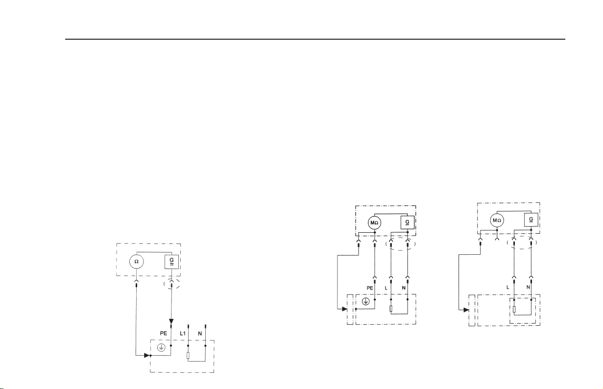
9.2 Measuring the protective conductor resistance
(with devices of protection class I)
The limit value is:
ΩΩ
0.3
Ω for devices with connecting cables up to 5 m,
ΩΩ
plus 0.1 Ω for every 7.5 m, but a mximum of 1.0 Ω.
Measuring principle circuit
protective conductor resistance PC I, Diagram M1
T ester
´Probe´
socket
Test line
Test socket
T est object
9.3 Measuring insulation resistance
The limit value is:
ΩΩ
1 M
Ω for devices of protection class I
ΩΩ
ΩΩ
2 M
Ω ffor devices of protection class II
ΩΩ
ΩΩ
0.25 M
Ω for devices of protection class III
ΩΩ
ΩΩ
0.3 M
Ω for devices of protection class I
ΩΩ
with switched-on heating elements
1)
Also applies for touchable conductive parts of test objects in
protection class I that are not connected to the protective conductor.
2)
If the required insulation resistance is not achieved in the case of test objects in
protection class I with heating elements with a total capacity ≥ 3.5 kW, the test object
is nevertheless rated as faultless if the protective conductor current does not exceed
the limit values.
Measuring principle circuit
Insulation resistance PC I, Diagram M2 PC II and III, Diagram M3
T ester
´Probe´
socket
Test line
If the insulation measurement is technically impossible, then a
&&
&
&&
Test socket
Test
object
1)
2)
´Probe´
socket
Test line
protective conductor current measurement (direct or differential
current method) must be carried out on test objects in PC I and a
touch current measurement on test objects in PC II.
17
Test socket

Operating manual for the TG uni 1 appliance tester
Conducting tests in accordance with VDE 0701 and 0702 - definition of standards
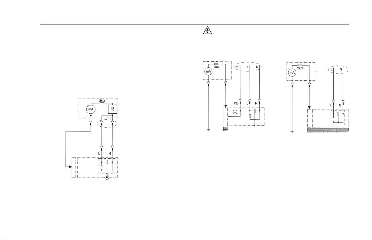
9.4a Measuring the protective conductor current
(with devices of protection class I)
The limit value is 3.5 mA.
In the case of test objects with heating elements with a total capacity
greater than 3.5 kW, the protective conductor current may not be
greater than 1 mA/kW heat output. The protective conductor current can
either be measured directly with the substitute leakage current method
or with the differential current method.
Measuring principle circuits
Protective conductor current – substitute leakage current method PC I, Diagram M4a
T ester
Test socket
T est object
Caution! The test object is supplied with mains voltage
during the test.
Protective conductor current - direct measurement PC I, Diagram M5
T ester
Test socket
T est object
Insulated installation
Protective conductor current – differential current method PC I, Diagram M6
T ester
Test socket
In case of test objects in PC I with touchable conductive parts that
&&
&
&&
are not connected to the protective conductor, an additional touch
current measurement must be carried out in line with PC II
(see Diagram 1 on Page 20)
T est object
18
Conducting tests in accordance with VDE 0701 and 0702 - definition of standards
Operating manual for the TG uni 1 appliance tester
9.4b Measuring touch current
(with devices of protection class II)
The limit value is 0.5 mA
The touch current can either be measured directly with the substitute
leakage current method or with the differential current method. This
measurement must also be carried out on devices of protection class I with
touchable conductive parts.
Measuring principle circuits
Touch current – substitute leakage current method PC II, Diagram M4b
T ester
´Probe´
socket
Test line
Test socket
Test
object
Caution! The test object is supplied with mains voltage
during the test.
Test socket
Touch current:
Test
object
T ester
Socket
´Probe´
Test line
Test
object
Insulated installation
Test socket
Direct measurement PC I, Diagram M8b Direct measurement PC II, Diagram M8a
T ester
Socket
´Probe´
Test line
Insulated installatio
Measurement of all touchable conductive parts of the test
object that are not connected to the protective conductor
9.5 Inspection the inscriptions
Safety-related inscriptions must be controlled and, where necessary,
renewed or supplemented in suitable form.
9.6 Function test (only required for DIN VDE 0701)
After completion of the electrical test, a function test shall be carried out on
the test object. A partial test can be sufficient.
9.7 Documentation
Once a test is passed, it should be documented in suitable form. If a test
object proves to be unsafe, this should be clearly indicated on the device
and the operator informed in writing. Recording the measured values and
the changes is recommended.
19

Operating manual for the TG uni 1 appliance tester
Test procedure in accordance with VDE 0701 and 0702
9.8 Diagram 1
Test procedure for devices of portection class I
Visual Inspection
Fig.15
Diagram M6
Measuring the
protective conductor
current, differential
current method
Diagram M1
Testing the protective
conductor resistance
Measuring the
insulation resistance
Yes
Diagram M5
Measuring the
protective conductor
current, direct
measurement
Can the test object be
insulated from earth?
Measuring the
protective conductor
current, substitute
leakage current
method
Function test, optional with VDE 0702, Fig.66
Diagram M4a
No
Yes
No
Diagram M6 Diagram M6 Diagram M5 Diagram M6
Measuring the
protective conductor
current, differential
current method
Function test and
inspection of
inscriptions
Test object with conductive
parts that are not connected
to the protective connector
Is measuring the insulation
resistance applicable?
Diagram M4a
Measuring the
protective conductor
current, substitute
leakage current
method
Fig.26
Fig.14
Test log, test report
(documentation)
Yes
No
Yes
Measuring the
protective conductor
current, differential
current method
Fig.27/28
As with ‘No’, but additional
measurements for these parts
in according with the test
procedure diagram for
protection class II
Can the test object be
insulated from earth?
Measuring the
protective conductor
current, direct
measurement
Fig.5Fig.5
20
No
Measuring the
protective conductor
current, differential
current method
End

9.9 Diagram 2
Test procedure for devices of protection class II and III
Protection class II and touchable
conductive parts of protection class I
that are not connected to the
protective conductor
Diagram M3
Measuring the
insulation resistance
Yes
Can the test object be
insulated from earth?
Yes
Operating manual for the TG uni 1 appliance tester
Test procedure in accordance with VDE 0701 and 0702
Visual Inspection
Protection class
II or III
Is measuring the insulation
resistance applicable?
No
Fig.36
Fig.35
Fig.35
Protection class II
Diagram 3
Measuring the insulation
resistance
No
Fig.5Fig.5
Yes
Can the test object be
insulated from earth?
No
Fig.41
Measuring the touch
current, differential
current method
Diagram M8a
Measuring the touch
current, direct
measurement
Function test, optional with VDE 0702, Fig.66
and not with PC III
Measuring the touch
current, substitute
leakage current
method
Diagram M4b
Fig.41 Fig.41 Diagram M8a
Measuring the touch
current, differential
current method
Function test and
inspection of
inscriptions
Diagram M4b
Measuring the touch
current, substitute
leakage current
method
Fig.45
Measuring the touch
current, differential
current method
Test log, test report
(documentation)
Fig.46/47
Measuring the touch
current, direct
measurement
21
Fig.41
Measuring the touch
current, differential
current method
End

Operating manual for the TG uni 1 appliance tester
Conducting tests in accordance with VDE 0701 and 0702 - PC I
10. Conducting tests with the TG uni 1appliance tester:
in accordance with DIN VDE 0701 and DIN VDE 0702, PC I
Connecting the test object
– Connect one end of the test line to the probe socket of the tester.
– Use the crocodile clip to connect the other end of the test line with a
metal part of the test object, which is connected to the protective
conductor.
Ensure that the crocodile clip makes a good contact with the metal part
of the test object.
– Connect the mains plug of the test object with the test socket of the
tester.
– Switch on the test object with the mains switch.
Switching on the appliance tester
Connect the mains plug of the tester to a properly connected and functional
earthed mains socket. Switch on the tester with the mains switch. Press the
large button in the Switch-on display (Fig. 12).
Entering the test date
The test date is entered or confirmed in the following display (Fig. 12a).
The tester is not equipped with a real-time clock!
&&
&
&&
Fig. 12 Fig. 13
Fig. 12a
Settings for measuring
Press the function button [Test procedure according to standard] in the ‘Main
menu’ (Fig. 13).
A display with the ‘Settings for measuring’ appears (Fig. 14). The standard
VDE 0701 is preset – change with the [Standard] button.
The protection class is set with the [PC] button (presetting: PC I). Selection
of the test procedure – with or without insulation resistance – is specified
with the [Ins y/n] button.
The headline shows the set measuring method for protective conductor
current [DIR.] or [DIF.] (see Point 6.3) and the setting for the manual [H] or
automatic [A] test procedure. The status line provides information about the
current settings throughout the test procedure. In the limit values line you
see the corresponding limit values.
Headline
Status line
Limit values line
Fig. 14
f
f
Test procedure:
- manual [H]
- automatic [A]
22
f

Operating manual for the TG uni 1 appliance tester
Conducting tests in accordance with VDE 0701 and 0702 -PC I
The [PE -> 5.0 m] button determines the length of the test object’s
connecting cable. With every press on this button the value is increased by
a further 7.5 m. The resulting limit value for the maximum protective
conductor resistance (see below) is visible in the limit values line.
Lenght of the connecting Limit value for protective
cable (PE) up to conductor resistance (R
5.0 m 0.3
12.5 m 0.4 Ω
20 m 0.5 Ω
27.5 m 0.6 Ω
35 m 0.7 Ω
42.5 m 0.8 Ω
50 m 0.9 Ω
With the function button [Hand/Auto] you determine whether the test
procedure should be carried out manually (by hand) or automatically.
Manual test procedure means that you have to confirm every test
&&
&
&&
stage by pressing the [OK] button to get to the next test stage.
Automatic test procedure means that a test stage automatically
&&
&
&&
changes to the next after 5 seconds - except for confirmation of
connection to the mains voltage (see Point 6.6, basic settings of
the tester).
Fig. 15
Ω
PE
)
Fig. 16
f
f
The headline shows the setting for a manual [H] or automatic [A] test
procedure. The [Cancel] button takes you back to the ‘Main menu’. To
move to the next stage press the [Next] button (also see Diagram 1 in Point
9.8).
If in the ‘Configuration menu’, direct measurement is set as the
&&
&
&&
measuring method for the protective conductor current, the
following warning message appears in the display: ‘ATTENTION!
The test object must be insulated during the following test stages!’.
Please follow this instruction without fail; otherwise the protective
conductor current cannot be measured correctly.
10.1 Visual inspection
The [->Next] button takes you to the first stage of the test: the visual
inspection (Fig. 15). The housing, connecting cable, inscriptions and other
parts should be inspected in this test. You confirm positive results of the
visual inspection by pressing the appropriate buttons – the display changes
from ‘not OK’ to ‘OK’ (Fig. 16).
10.2 Protective conductor resistance
The limit value is:
0.3 Ω for devices with connecting cables up to 5 m,
plus 0.1 Ω for every 7.5 m, but only up to a maximum of 1.0 Ω
(see table on Page 22)
Fig. 17
f
f
23

Operating manual for the TG uni 1 appliance tester
Conducting tests in accordance with VDE 0701 and 0702 - PC I
The [->Next] button takes you to the first electrical test: the protective
conductor resistance (Fig. 17).
The measured value appears in the middle of the display in large figures.
The star sign on the left side of the display blinks when the
&&
&
&&
measuring process is running (the values are being measured).
The
[OK] button appears when the measured value is determined.
The corresponding limit value LV as well as the instantaneous test current
(+) is also displayed.
By pressing the [Help] button you change to the help display for the
protective conductor resistance measurement. A measuring principle circuit
corresponding to the figure in this operating manual and a short help text are
displayed.
After pressing the [End] button you return to the measuring display.
With the manual test procedure the measuring display remains until the [OK]
button is pressed. In the next stage the polarity of the test current (–) is
reversed and the protective conductor resistance remeasured.
During the measurement, the connecting cable of the test object
&&
&
&&
should be moved, section by section, along its whole length, in
order to find broken conductors or weak points.
Fig. 18
Fig. 19
f
10.3 Insulation resistance (compare with Point 10.4a)
The limit value is:
1.0 MΩ (PC I)
2.0 MΩ for touchable conductive parts that are not connected to the
protective conductor (PC I).
0.3 MΩ for devices of PC I with switched-on heating elements ≥ 3.5 kW *)
*) If the required insulation resistance is not achieved in the case of devices in protection class I
with heating elements with a total capacity of 3.5 kW, the device is nevertheless rated as faultless if
the protective conductor current does not exceed the limit values. (tester setting – PC: Ie).
If you have selected a test procedure with insulation resistance in the
‘Settings for measuring’, the measuring display for the insulation resistance
measurement (Fig. 19) appears after you press the [OK] button. Beside the
measured value, the level of the test voltage is also displayed (min. 500 V DC).
The star sign on the left side of the display blinks when the
&&
&
&&
measuring process is running (the values are being measured).
[OK] button appears when the measured value is determined.
The
A help display with a measuring principle circuit and a help text is also
available here.
Fig. 20
f
24

Operating manual for the TG uni 1 appliance tester
Conducting tests in accordance with VDE 0701 and 0702 -PC I
10.4a Protective conductor current (substitute leakage current)
The limit value is:
3.5 mA (PC I)
In the case of devices with heating elements with a total capacity
greater than 3.5 kW, the protective conductor current may not be
greater than 1 mA/kW heat output.
The [OK] button takes you further to the measuring display ‘Protective
conductor current’ (according to the substitute leakage current principle).
Here, too, the related limit value is displayed beside the measured value
(Fig. 20).
Warning!
With the test procedure according to DIN VDE 0702 and a test with
insulation resistance, the protective conductor current is
always measured by the tester with connection to the mains
voltage (direct method or according to the differential current
principle).
Fig. 21
f
Fig. 22
f
10.4b Protective conductor current (compare with Point 10.4a)
The limit value is:
3.5 mA (PC I)
In the case of devices with heating elements with a total capacity
greater than 3.5 kW, the protective conductor current may not be
greater than 1 mA/kW heat output.
If you have selected a test procedure without insulation resistance in the
‘Settings for measuring’, the tester changes to measuring the protective
conductor current (Points 3. – Insulation resistance and 4a. – Substitute
leakage current, are omitted).
Caution! The test object is supplied with mains voltage
during the test.
After pressing the [OK] button you will see a warning about connection to
the mains current (Fig. 21).
Fig. 23
f
25

Operating manual for the TG uni 1 appliance tester
Conducting tests in accordance with VDE 0701 and 0702 - PC I
With your assent – by pressing the large button – the display changes to
measuring the protective conductor current and the mains voltage is
connected – the test object is put into operation!
You can see the measured value in the middle of the display, with the
related limit value to the right (Fig. 22).
The star sign on the left side of the display blinks when the
&&
&
&&
measuring process is running (the values are being measured).
[OK] button appears when the measured value is determined.
The
The symbol
With the [Help] button, you can also go to the help display from here.
Pressing the [OK] button automatically reverses the polarity of the mains
plug of the test object (Fig. 23).
A compulsory break of 8 seconds serves to halt any running motors.
Thereafter, you are again warned about connection to the mains voltage.
After confirmation with the [OK] button, the mains voltage is reconnected
and the measurement of the protective conductor current repeated (Fig. 21
and 22).
&&
&
&&
Fig. 24 Fig. 25
blinks to indicate the connection to the mains voltage.
Selecting the measuring method for protective conductor current -
see Point 6.3 Setting the measuring method for protective
conductor current measurement.
f
10.5 Function test (only required for DIN VDE 0701)
Press the [OK] button to go to the menu ‘Function test’ menu.
Here a function test of the test object is carried out in accordance with DIN
VDE 0701 (Fig. 24).
Caution! The test object is supplied with mains voltage
during the test.
Before connection is made to the mains voltage a warning message
appears in the display. The automatic test procedure is stopped; it only
proceeds when a button is pressed (Fig. 25).
After you have confirmed the connection of the mains voltage by pressing
the button, the tester changes to the function test display (Fig. 26).
The display shows the instantaneous mains voltage, the load current, the
active power, apparent power and reactive power, the power factor and
mains frequency.
10.6 Inspecting the inscriptions
At this point the values displayed in the function test should be compared
with the data on the type plate of the test object.
Fig. 26
f
26

Operating manual for the TG uni 1 appliance tester
Conducting tests in accordance with VDE 0701 and 0702 - PC I
10.7 Documentation
After pressing the [OK] button, the display changes to the ‘Test result’
screen (Fig. 27).
Here you can see all the measurement results with the related limit values.
If the measurement results of the electrical values, the visual inspection and
the function test were all in order, the following message appears:
‘Test OK’.
If the test was not successful the message says:
‘Test not OK!’.
At this point you can cancel the test with the [Cancel] button (the display
goes back to the ‘Settings for measuring’ screen) or switch to the ‘Memory
menu’ with the [->Next] button.
In the ‘Memory menu’ (Fig. 28) you can use the function button [Change
memory] to switch the storage location for measurement results between
the device-internal memory and the MMC memory card.
The current setting is shown in the menu headline.
Fig. 27 Fig. 28 Fig. 29
With the [Save] button the display changes to ‘Enter appliance identification’.
Here you can enter a max. 10-character test object ID number or read it in
from the barcode label with the optionally available barcode scanner (Fig. 29).
The barcode scanner is connected to the RS232 socket of the
&&
&
&&
tester
Symbols for memory settings:
- internal memory
- MMC memory card
f
f
f
f
27

Operating manual for the TG uni 1 appliance tester
Conducting tests in accordance with VDE 0701 and 0702 - PC I
Confirm the entry with the [OK] button – the display changes (Fig. 30) and
shows the ID number, the name of the inspector and the date (see Points
6.4 and 6.7 for entering the inspector’s name and the date). The data is
saved in the memory with the [Save] button.
A confirmation message appears (Fig. 31) – continue with the [End] button.
With the entry of an already used ID number, the data is „attached“ as a
new test to this ID number.
After the saving process, the display changes to the ‘Settings for measuring’
menu – the tester is ready for the next test (Fig. 32).
Fig. 30
Fig. 31 Fig. 32
f
The test results can be saved on a PC with the supplied PC programme or
printed from there in the form of a test log. To do this, make the USB
connection between the tester and the PC (USB cable supplied with the
tester) or transfer the saved data from the MMC memory card to the PC.
Procedure on the PC – see the operating instructions for the PC software.
General information
Every test stage during which the test object is supplied with mains voltage
is time limited for reasons of safety! The maximum duration of this test
stage is approx. 4 minutes. After this time has expired a message appears
in display. At this point you can continue the test with the [->Next] button or
cancel it with the [Cancel] button.
f
28

Operating manual for the TG uni 1 appliance tester
Conducting tests in accordance with VDE 0701 and 0702 - PC II
11. Conducting tests with the TG uni 1 appliance tester:
in accordance with DIN VDE 0701 and DIN VDE 0702, PC II
Connecting the test object
– Connect one end of the test line to the probe socket of the tester.
– Use the crocodile clip to connect the other end of the test line with a
touchable metal part of the housing of the test object.
Ensure that the crocodile clip makes a good contact with the metal part of
the test object.
– Connect the mains plug of the test object with the test socket of the tester.
– Switch on the test object with the mains switch.
Switching on the appliance tester
Connect the mains plug of the tester to a properly connected and functional
earthed mains socket. Switch on the tester with the mains switch.
Press the large button in the Switch-on display (Fig. 33).
Entering the test date
The test date is entered or confirmed in the following display (Fig. 33a).
The tester is not equipped with a real-time clock!
&&
&
&&
Fig. 33 Fig. 34
Fig. 33a
Settings for measuring
Press the function button [Test procedure according to standard] in the Main
menu (Fig. 34).
A display with the ‘Settings for measuring’ appears (Fig. 35).
The standard VDE 0701 is preset – change with the [Standard] button. The
protection class is set with the [PC] button (Presetting: PC I). Press the
[PC] button to change the setting to protection class II. Selection of the test
procedure – with or without insulation resistance – is specified with the [Ins
y/n] button.
The headline shows the set measuring method for touch current [DIR.] or
[DIF.] (see ‘Configuration menu’ Point 6.3) and the setting for the manual [H]
or automatic [A] test procedure.
The status line provides information about the current settings throughout the
test procedure.
Headline
Status line
Limit values line
Fig. 35
f
Test procedure:
- manual [H]
- automatic [A]
f
f
29
f

Operating manual for the TG uni 1 appliance tester
Conducting tests in accordance with VDE 0701 and 0702 - PC II
The corresponding limit values are given in the limit values line.
With the function button [Hand/Auto] you determine whether the test
procedure should be carried out manually (by hand) or automatically.
Manual test procedure means that you have to confirm every test
&&
&
&&
stage by pressing the [OK] button to get to the next test stage.
Automatic test procedure means that a test stage automatically
&&
&
&&
changes to the next after 5 seconds - except for confirmation of
connection to the mains voltage (see Point 6.6, basic settings of
the tester)
The [Cancel] button takes you back to the ‘Main menu’.
To move to the next stage press the [->Next] button (also see Diagram 2 in
Point 9.9).
If, in the Configuration menu, direct measurement is set as the
&&
&
&&
measuring method for the protective conductor current/ touch
current (Point 6.3), the following warning message appears in the
display:
‘ATTENTION! The test object must be insulated during the
following test stages!’
Please follow this instruction without fail; otherwise the touch
current cannot be measured correctly.
Fig. 36
f
11.1 Visual inspection
The [->Next] button takes you to the first stage of the test, the visual
inspection (Fig. 36).
The housing, connecting cable, inscriptions and other parts should be
inspected in this test. You confirm positive results of the visual inspection
by pressing the appropriate buttons – the display changes from ‘not OK’ to
‘OK’ (Fig. 37).
11.2 Insulation resistance (compare with Point 11.3b)
The limit value is:
2.0 MΩ (SK II) *)
*)
Also applies for touchable conductive parts of devices in protection class I that
are not connected to the protective conductor.
If you have selected a test procedure with insulation resistance in the
‘Settings for measuring’, the measuring display for insulation resistance
measurement (Fig. 38) appears after you press the [->Next] button. Beside
the measured value, the level of the test voltage is also displayed (min. 500
V DC).
The star sign on the left side of the display blinks when the
&&
&
&&
measuring process is running (the values are being measured).
The
[OK] button appears when the measured value is determined.
By pressing the [Help] button you go to a help display with the measuring
principle circuit and a help text.
Fig. 38Figb. 37
f
30

Operating manual for the TG uni 1 appliance tester
Conducting tests in accordance with VDE 0701 and 0702 - PC II
11.3a Touch current (substitute leakage current)
The limit value is:
0.5 mA
This measurement must also be carried out on devices of
protection class I with touchable conductive parts that are not
connected to the protective conductor.
Press the [OK] button to go to the ‘Touch current’ measuring display.
The measurement is made in accordance with the substitute leakage
current principle.
Here, too, the corresponding limit value is displayed beside the measured
value (Fig. 39).
The star sign on the left side of the display blinks when the
&&
&
&&
measuring process is running (the values are being measured).
The
[OK] button appears when the measured value is determined.
A help display is also available if you press the [Help] button.
Warning!
With the test procedure according to DIN VDE 0702 and a test with
insulation resistance, the touch current is always measured
by the tester with connection to the mains voltage (direct method
or according to the differential current principle).
Fig. 39 Fig. 40
f
f
11.3b Touch current (compare with Point 11.2)
The limit value is:
0.5 mA
This measurement must also be carried out on devices of
protection class I with touchable conductive parts that are not
connected to the protective conductor.
If you have selected a test procedure without insulation resistance in the
‘Settings for measuring’, the tester changes to measuring the touch current
(Points 11.2. Insulation resistance and 11.3a. Touch current / Substitute
leakage current, are omitted)
Caution! The test object is supplied with mains voltage
during the test.
After pressing the [->Next] button the display changes and you receive a
warning message about the connection to the mains current (Fig. 40).
With your assent – by pressing the large button – the display changes to
measuring the touch current and the mains voltage is connected – the test
object is put into operation!
You can see the measured value in the middle of the display, with the
related limit value to the right (Fig. 41).
Fig. 41
f
f
31

Operating manual for the TG uni 1 appliance tester
Conducting tests in accordance with VDE 0701 and 0702 - PC II
The star sign on the left side of the display blinks when the
&&
&
&&
measuring process is running (the values are being measured).
The [OK] button appears when the measured value is determined.
The symbol blinks to indicate the connection to the mains voltage.
With the [Help] button, you can also go to the help display from here.
Pressing the [OK] button automatically reverses the polarity of the mains
plug of the test object (Fig. 42).
A compulsory break of 8 seconds serves to halt any running motors.
Thereafter, you are again warned about the connection to the mains
voltage. After confirmation by pressing the button, the mains voltage is
reconnected and the measurement of the touch current repeated (Fig. 40
and 41).
Selecting the measuring method for touch current - see Point 6.3,
&&
&
&&
Setting the measuring process for protective conductor current
measurement.
Fig. 42
Fig. 43 Fig. 44
f
11.4 Function test (only required for DIN VDE 0701)
Press the [OK] button to go to the function test.
Here a function test of the test object is carried out in accordance with DIN
VDE 0701 (Fig. 43).
Caution! The test object is supplied with mains voltage
during the function test.
Before connection is made to the mains voltage a warning message
appears in the display. The automatic test procedure is stopped; it only
proceeds when a button is pressed (Fig. 44).
After you have confirmed the connection of the mains voltage by pressing
the button, the tester changes to the function test display (Fig. 45).
The display shows the instantaneous mains voltage, the load current, the
active power, apparent power and reactive power, the power factor and
mains frequency.
11.5 Inspecting the inscriptions
At this point the values displayed in the function test should be compared
with the data on the type plate of the test object.
f
32

Operating manual for the TG uni 1 appliance tester
Conducting tests in accordance with VDE 0701 and 0702 - PC II
11.6 Documentation
After pressing the [OK] button, the display changes to the ‘Test result’
screen. Here you can see all the measurement results with the related limit
values (Fig. 46).
If the measurement results of the electrical values, the visual inspection and
the function test were all in order, the following message appears: ‘Test OK’.
If the test was not successful the message says: ‘Test not OK!’.
At this point you can cancel the test with the [Cancel] button (the display
goes back to the ‘Settings for measuring’ screen) or switch to the ‘Memory
menu’ with the [->Next] button.
Fig. 45
Fig. 46
f
f
In the ‘Memory menu’ you can use the function button [Change memory] to
switch the storage location for measurement results between the deviceinternal memory and the MMC memory card. The current setting is shown
in the menu headline (Fig. 47).
With the [Save] button the display changes to ‘Enter appliance identification’.
Here you can enter a 10-character test object ID number or read it in from
the barcode label with the connected barcode scanner.
Connecting the barcode scanner – see Page 27.
&&
&
&&
Symbols for die memory settings:
- internal memory
- MMC memory card
Fig. 47
f
f
33

Operating manual for the TG uni 1 appliance tester
Conducting tests in accordance with VDE 0701 and 0702 - PC II
Confirm the entry with the [OK] button – the display changes (Fig. 49) and
shows the ID number, the name of the inspector and the date (see Points
6.4 and 6.7 for entering the inspector’s name and the date). The data is
saved in the memory with the [Save] button.
A confirmation message appears (Fig. 50) – continue with the [End] button.
With the entry of an already used ID number, the data is “attached“
&&
&
&&
as a new test to this ID number.
After the saving process, the display changes to the ‘Settings for measuring’
menu – the tester is ready for the next test.
Fig. 48
Fig. 49
f
The test results can be saved on a PC with the supplied PC programme or
printed from there in the form of a test log. To do this, make the USB
connection between the tester and the PC (USB cable supplied with the
tester) or transfer the saved data from the MMC memory card to the PC.
Procedure on the PC – see the operating instructions for the supplied PC
software.
General information
Every test stage during which the test object is supplied with mains voltage
is time limited for reasons of safety!
The maximum duration of this test stage is approx. 4 minutes. A warning
message then appears in display.
At this point you can continue the test with the [->Next] button or cancel it
with the [Cancel] button.
Fig. 50
f
34

Operating manual for the TG uni 1 appliance tester
Conducting tests in accordance with VDE 0701 and 0702 - PC III
12. Conducting tests with the TG uni 1 appliance tester: in
accordance with DIN VDE 0701 and DIN VDE 0702, PC III
Connecting the test object
– Connect one end of the test line to the probe socket of the tester.
– Use the crocodile clip to connect the other end of the test line with a
touchable metal part of the housing of the test object. Ensure that the
crocodile clip makes a good contact with the metal part of the test object.
– Connect the low voltage connection of the test object with the test socket
of the tester (see Diagram M3 on page 17).
– Switch the test object on.
Switching on the appliance tester
Connect the mains plug of the tester to a properly connected and functional
earthed mains socket. Switch on the tester with the mains switch.
Press the large button in the Switch-on display (Fig. 51).
Entering the test date
The test date is entered or confirmed in the following display (Fig. 51a).
The tester is not equipped with a real-time clock!
&&
&
&&
Fig. 51 Fig. 52
Fig. 51a
Settings for measuring
Press the function button [Test procedure according to standard] in the Main
menu (Fig. 52).
A display with the ‘Settings for measuring’ appears (Fig. 53).
The standard VDE 0701 is preset – change with the [Standard] button.
The protection class is set with the [PC] button. Press the [PC] button to
change the setting to protection class III. The headline shows the setting for
a manual [H] or automatic [A] test procedure.
The status line provides information about the current settings throughout the
test procedure. In the limit value line you now see the corresponding limit
value of the insulation resistance.
With the function button [Hand/Auto] you determine whether the test
procedure should be carried out manually (by hand)
or automatically.
Headline
Status line
Limit values line
Fig. 53
f
Test procedure:
- manual [H]
- automatic [A]
f
f
35
f

Operating manual for the TG uni 1 appliance tester
Conducting tests in accordance with VDE 0701 and 0702 - PC III
Manual test procedure means that you have to confirm every test
&&
&
&&
stage by pressing the [OK] button to get to the next test stage.
Automatic test procedure means that a test stage automatically
&&
&
&&
changes to the next after 5 seconds - except for confirmation of
connection to the mains voltage (see Point 6.6, basic settings of
the tester)
The [Cancel] button takes you back to the ‘Main menu’.
To move to the next stage - also see Diagram 2 in Point 9.9.
&&
&
&&
12.1 Visual inspection
The [->Next] button takes you to the first stage of the test, the visual
inspection (Fig. 54).
The housing, connecting cable, inscriptions and other parts should be
inspected in this test.
You confirm positive results of the visual inspection by pressing the
appropriate buttons – the display changes from ‘not OK’ to ‘OK’ (Fig. 55).
Fig. 54
Fig. 55 Fig. 56
f
12.2 Insulation resistance
The limit value is:
0.25 MΩ (PC III)
After pressing the [->Next] button, the display for the insulation resistance
measurement appears (Fig. 56).
Beside the measured value, the level of the test voltage is also displayed
(min. 500 V DC).
The star sign on the left side of the display blinks when the
&&
&
&&
measuring process is running (the values are being measured).
The [OK] button appears when the measured value is determined.
A help display with a measuring principle circuit and a help text is also
available here.
Since the tester cannot provide the specific low voltage for the test
&&
&
&&
object, a function test is not carried out for test objects in PC III.
Alternatively, the test object can be tested according to PC II with
the appropriate power supply unit - see Point 11 on Page 29.
f
36

Operating manual for the TG uni 1 appliance tester
Conducting tests in accordance with VDE 0701 and 0702 - PC III
12.3 Documentation
After pressing the [OK] button, the display changes to the ‘Test result’
screen (Fig. 57).
Here you can see all the measurement results with the related limit values.
If the measurement results of the electrical values, the visual inspection and
the function test were all in order, the following message appears:
‘Test OK’.
If the test was not successful the message says:
‘Test not OK!’.
At this point you can cancel the test with the [Cancel] button (the display
goes back to the ‘Settings for measuring’ screen) or switch to the ‘Memory
menu’ with the [->Next] button.
Fig. 57
Fig. 58 Fig. 59
f
f
In the ‘Memory menu’ you can use the function button [Change memory] to
switch the storage location for measurement results between the deviceinternal memory and the MMC memory card. The current setting is shown
in the menu headline (Fig. 58).
With the [Save] button the display changes to ‘Enter appliance identification’.
Here you can enter a 10-character test object ID number or read it in from
the barcode label with the connected barcode scanner (Abb. 59).
Connecting the barcode scanner - see Page 27.
&&
&
&&
Symbols for memory settings:
- internal memory
- MMC memory card
f
f
37

Operating manual for the TG uni 1 appliance tester
Conducting tests in accordance with VDE 0701 and 0702 - PC III
Confirm the entry with the [OK] button – the display changes (Fig. 60) and
shows the ID number, the name of the inspector and the date. The data is
saved in the memory with the [Save] button.
A confirmation message appears (Fig. 61) – continue with the [End] button.
With the entry of an already used ID number, the data is “attached“
&&
&
&&
as a new test to this ID number
Fig. 60
Fig. 61
f
After the saving process, the display changes to the ‘Settings for measuring’
menu – the tester is ready for the next test (Fig. 62).
The test results can be saved on a PC with the supplied PC programme or
printed from there in the form of a test log. To do this, make the USB
connection between the tester and the PC (USB cable supplied with the
tester) or transfer the saved data from the MMC memory card to the PC.
Procedure on the PC – see the operating instructions for the supplied PC
software.
Fig. 62
f
38

13. Conducting tests with the appliance tester TG uni 1:
in accordance with DIN VDE 0702, all protection classes
The function test is not expressly required in the standard DIN VDE 0702.
With every test procedure carried out according to DIN VDE 0702, the tester
offers the function test as an option (also see Points 9.8 and 9.9).
A display offering this option appears at the appropriate point.
(Fig. 63)
Fig. 63
Wth the exception of the function test, the test procedure according to
&&
&
&&
DIN VDE 0702 is essentially identical with the test procedure
according to DIN VDE 0701.
Operating manual for the TG uni 1 appliance tester
Conducting tests in accordance with VDE 0702
39

Operating manual for the TG uni 1 appliance tester
Conducting tests in accordance with VDE 0701 and 0702 - special test procedure
14. Conducting tests with the appliance tester TG uni 1 in
accordance with DIN VDE 0701 and DIN VDE 0702 – special test
procedure according to customer-specific settings
This input area is locked by a code key.
&&
&
&&
Please contact us for further information:
Tel. +49 (0)911 / 3502-0, Fax +49 (0)911 / 3502-307.
If several tests should be carried out with an identical setting of the tester,
the tester can be „pre-programmed“ for a test series – according to VDE
0701 or 0702 (also see Point 6.8).
In the following example the tester is set for the test according to DIN VDE
0702 (periodic inspection), differential current measuring method, PC I and
without insulation resistance.
The settings are entered in Setup in the Configuration menu, see Fig. 64 to
Fig. 75.
Fig. 64
f
Fig. 65
Fig. 66
f
40

Conducting tests in accordance with VDE 0701 and 0702 - special test procedure
Operating manual for the TG uni 1 appliance tester
Fig. 67
f
Fig. 70
Fig. 73
f
The tester is now ready to start new tests
f
Fig. 68
f
Fig. 71
f
f
Fig. 74 Fig. 75
f
Fig. 69
f
Fig. 72
f
41

Operating manual for the TG uni 1 appliance tester
Technical data
15. Tecnical data
Protective conductor resistance:
Measuring range 0 ... 2 Ω
Display range 0 ... 1.000 Ω
Resolution 1 mΩ
Error ± 5 % ± 10 digit
Measurement current min. 200 mA DC (+/–)
Insulation resistance:
Measuring range 200 kΩ ... 200 MΩ
Display range 0.200 ... 200 MΩ
Resolution 0.001 kΩ
Error ± 5 % ± 10 digit
Measurement voltage min. 500 V DC
Substitute leakage current:
Measuring range 0 ... 20 mA
Display range 0 ... 20 mA
Resolution 0,001 mA
Error ± 5 % ± 10 digit
Measurement voltage 220 V AC
Protective conductor current, direct:
Measuring range 0 ... 5 mA
Display range 0 ... 5 mA
Resolution 0.001 mA
Error ± 5 % ± 10 digit
Touch current, direct:
Measuring range 0 ... 1 mA
Display range 0 ... 1 mA
Resolution 0.001 mA
Error ± 5% ± 10 digit
Protective conductor current, differential current:
Measuring range 0 ... 5 mA
Display range 0 ... 5 mA
Resolution 0.001 mA
Error ± 5 % ± 10 digit
Touch current, differential current:
Measuring range 0 ... 1 mA
Display range 0 ... 1 mA
Resolution 0.001 mA
Error ± 5% ± 10 digit
42

Operating manual for the TG uni 1 appliance tester
Technical data
15.1 Technical data for function tests
Voltage:
Measuring range 190 ... 250 V
Display range 190.0 ... 250.0 V
Resolution 0.1 V
Error ± 1 % ± 5 digit
Current:
Measuring range 0 ... 16 A
Display range 0 ... 16.00 A
Resolution 0.001 mA
Error ± 2 % ± 10 digit
Active power:
Measuring range 0 ... 3700 W
Display range 0 ... 3700 W
Resolution 100 mW
Error ± 2 % ± 10 digit
Reactive power:
Measuring range 0 ... 3700 Var
Display range 0 ... 3700 Var
Resolution 100 mVAr
Error ± 2 % ± 10 digit
Apparent power:
Measuring range 0 ... 3700 VA
Display range 0 ... 3700 VA
Resolution 100 mVA
Error ± 2 % ± 10 digit
Power factor:
Measuring range 0 cap. ... 1 ... 0 ind.
Display range 0.00 cap. ... 1 ... 0.00 ind.
Resolution 0.01
Error ± 3 %
Frequency:
Measuring range 40 ... 50 ... 60 Hz
Display range 40.0 ... 50.0 ... 60.0 Hz
Resolution 0.1 Hz
Error ± 3 %
15.2 General technical data
Internal memory capacity 16 MB
MMC memory card capacity 128 bis 256 MB
Serial interfaces 9600 baud, no parity, 1 stopp bit
USB connection USB 1.1
Power supply 230 V AC, 50 Hz, approx. 10 VA
Degree of pollution 2
Overvoltage category CAT II 300 V
Electrical safety according to EN61010-1 / VDE 0411
EMC
Emitted interference according to EN 55011
Interference resistance according to EN 61000-4-2
Dimensions approx. 300 x 250 x 130 mm (W x D x H)
Weight approx. 3.1 kg (incl. accessories)
Optional barcode scanner with serial interface (9-pin Sub-D) and internal
power supply via pin 9.
43

16. Manufacturer’s guarantee conditions
The TG uni 1 appliance tester is subject to a strict quality inspection.
Nevertheless, we grant a 24 month manufacturer’s guarantee in the case of
malfunctions during normal daily usage.
Manufacturing or material faults will be remedied, free of charge, as long as
the device shows no signs of third party actions and is unopened before it
is sent back to us.
Damage resulting from the device being dropped or mishandled is excluded
from guarantee claims.
GOSSEN Müller & Weigert
Kleinreuther Weg 88
D-90408 Nürnberg, Germany
Tel. +49(0)911 3502-0
Fax +49(0)911 3502-307
info@g-mw.de · www.g-mw.de
Subject to errors and technical modifications!
2786688215GB 02.08
CE
44
 Loading...