

Page 1
TG basic 1
Appliance tester for testing
protective measures
in accordance with DIN VDE 0701-0702
(DIN EN 62638)
Operating manual
(Version 1.00.8 or higher)
Page 2

Operating manual for the TG basic 1 appliance tester
Table of contents Page
1. Safety information 3
2. Introduction 4
3. Safety instructions 5
4. Appropriate usage 6
5. Operating elements 7
6. Starting up 8
6.1. Initial equipping or battery replacement 8
6.2. Switching the tester on and off
Selecting the measuring sequences 8
7. Explanation of terminology 11
7.1. Protection class I (PC I) 11
7.2. Protection class II (PC II) 11
7.3. Protection class III (PC III) 11
7.4. Protective conductor resistance (RPE)11
7.5. Insulation resistance (R
7.6. Substitute leakage current (IEA)12
)11
ISO
7.7. Visual inspection 12
8. Conducting tests in accordance with
DIN VDE 0701-0702; Definition of standards 13
8.1. Visual inspection 13
8.2. Measuring the protective conductor resistance 13
8.3. Measuring the insulation resistance 13
8.4. Measuring the substitute leakage current
for devices of protection class I 14
8.5. Measuring the substitute leakage current for devices
of protection class II 15
8.6. Inspecting the inscriptions 15
9. Test procedures 16
9.1. Testing devices of protection class I 16
9.1.1. Measuring the protective conductor resistance 16
9.1.2. Measuring the insulation resistance 18
9.1.3. Measuring the substitute leakage current 19
9.1.4. Test assessment 19
9.2. Testing devices of protection class II 20
9.2.1. Measuring the insulation resistance 20
9.2.2. Measuring the substitute leakage current 20
9.2.3. Test assessment 21
9.3. Cable test 21
9.3.1. Protective conductor resistance 22
9.3.2. Insulation resistance 22
9.3.3. Cable test 22
9.4. Measuring the voltage at an external earthed
mains socket 23
10. Checking the battery voltage 24
11. Technical data 24
12. Notes on cleaning 25
13. Calibrating the tester 25
14. Manufacturer’s guarantee conditions 26
GOSSEN Müller & Weigert
Page 3
Operating manual for the TG basic 1 appliance tester
1. Safety information
Tests on the electrical safety of electrical appliances may only be
carried out by qualified electricians or under their supervision.
Carefully read through the following safety information before
starting up the TG Basic appliance tester.
Symbols used in the operating manual and on the appliance
tester:
Warning of a hazardous situation. Follow the operating
manual.
Caution! Dangerous voltage, danger of electric shock.
Note: Please be sure to follow the manual!
&&
&
&&
CE mark of conformity
The operating manual contains information and notes
&&
&
&&
which are necessary for the safe operation and use of the
appliance tester. Before using (starting up) the appliance
tester, the operating manual should be carefully read
through and followed in all points.
If the manual is not observed or if you fail to observe the
&&
&
&&
warnings and notes, serious injury to the user and
damage to the appliance tester can occur.
All the technical data and quoted standards in this manual
&&
&
&&
are up-to-date at the time of going to press and have
been determined to the best of our knowledge,
nevertheless this data may be subject to errors and
printing errors. Therefore no legal responsibility or any
other liability can be accepted for incorrect information or
the consequences of this information.
The respective provisions, regulations and standards
are the authorities defining the procedures to be
followed when conducting tests.
There is no intention to infringe on any existing patents
and other property rights with this publication.
GOSSEN Müller & Weigert
3
Page 4

Operating manual for the TG basic 1 appliance tester
2. Introduction
You have acquired a high-grade device from the company Gossen
Müller & Weigert with which you can carry out repeatable
measurements over a very long period of time.
The product was calibrated during the manufacturing process in
accordance with the specified operating procedures.
The TG basic 1 appliance tester, hereafter referred to as the
tester, has been developed for carrying out the following
measurements for testing the safety of electrical appliances in
accordance with DIN VDE 0701-0702 (BGV A3):
- Measuring the protective conductor resistance
- Measuring the insulation resistance
- Measuring the substitute leakage current
- Testing of IEC and extension cables
- Measuring the power socket voltage
Scope of delivery
1 qty TG basic 1 appliance tester
1 qty set of measuring accessories with safety test line, safety
crocodile clip and safety test tip
6 qty batteries of type AA (Mignon)
1 qty IEC connection cable, 0.5 m
1 qty carrying bag
1 qty operating manual
Transport and storage
Please retain the original packaging for dispatch at a later date,
e.g. for calibration.
Transport damage that occurs due to inadequate packaging is not
covered by the manufacturer’s guarantee.
The appliance tester must be stored in a dry, closed room. If the
device is transported in extreme temperatures, it requires at least
2 hours acclimatisation before being switched on.
GOSSEN Müller & Weigert
4
Page 5
Operating manual for the TG basic 1 appliance tester
3. Safety instructions
The appliance tester was constructed and tested in accordance
with the applicable safety regulations and left the factory in a
faultless safety condition. In order to maintain this condition and
ensure safe operation, the user must observe the instructions and
warnings contained in this operating manual.
With all work, the applicable accident prevention
&&
&
&&
regulations of the trade associations for electrical systems
and equipment must be observed.
To avoid electric shock, the applicable safety regulations
and DIN-VDE regulations regarding high touch voltage
must be observed without fail when working with voltages
greater than 120 V DC or 50 V AC.
Measuring at a dangerous proximity to electrical systems should
only be carried out under the instruction of a responsible
electrician, and never alone.
Check the appliance tester and the connecting cables for external
damage before every new operation.
Make sure that the appliance tester and the cable connections
are in faultless condition.
The appliance tester may not be used if one or more functions fail
or if functional readiness is not evident.
The measuring lines and the measuring accessories may
only be touched in the designated handling areas.
Touching measuring connections, e.g. test tips, must be
avoided under all circumstances.
If the safety of the operator is no longer guaranteed the
&&
&
&&
appliance tester must be decommissioned and secured
against unwanted use. This is the case if the device:
– Shows obvious signs of damage
– No longer carries out the required measurements
– Has been stored under adverse conditions for too long
GOSSEN Müller & Weigert
5
Page 6

Operating manual for the TG basic 1 appliance tester
4. Appropriate usage
The tester may only be used under the conditions and for the
purposes for which it has been designed. It is particularly
important to observe the safety instructions and the technical data
regarding ambient conditions and usage in a dry environment.
The appliance tester may not be used for measuring in electrical
systems.
Operational safety is no longer guaranteed in the case of
modifications or conversions that have not been carried out by the
manufacturer.
Maintenance or calibration work may only be carried out by the
manufacturer.
Subject the appliance tester to an electromagnetic field can
impair the function of the appliance tester.
In order to avoid damaging the appliance tester, the test socket
and the test line may not be connected to an external voltage
source.
Only the supplied original measuring lines or equivalent safety
measuring accessories may be used!
GOSSEN Müller & Weigert
6
Page 7
Operating manual for the TG basic 1 appliance tester
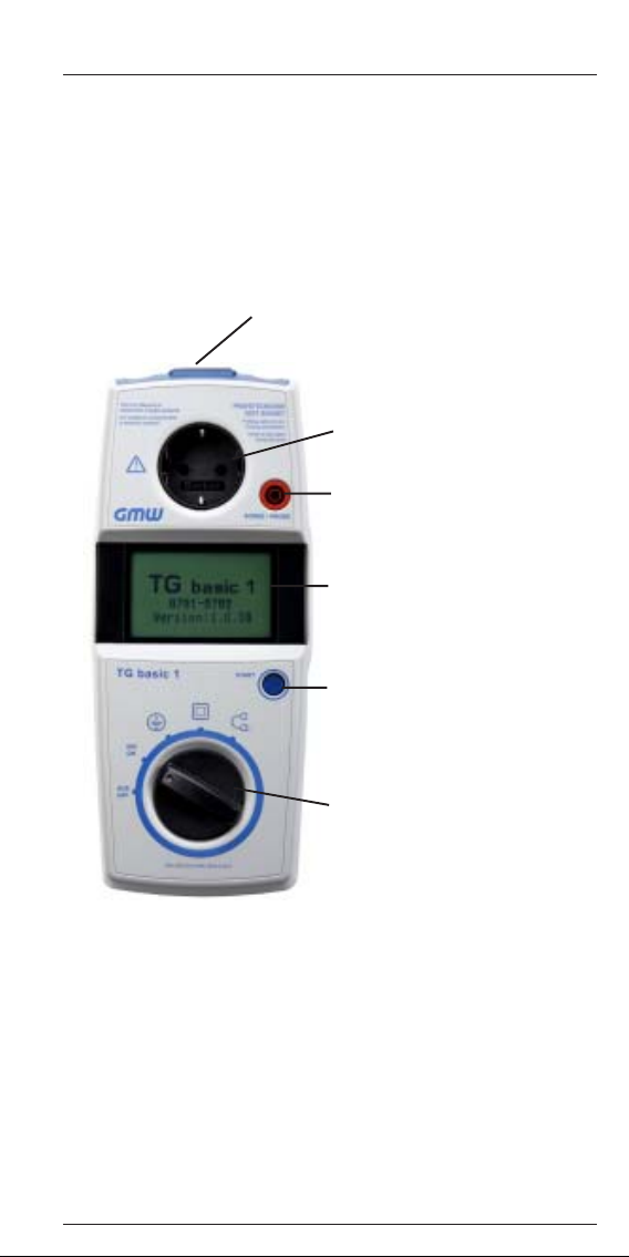
5. Operating elements
Explanation of the appliance tester’s connections, operating
elements and displays.
In-case socket for IEC appliances, for
testing connection and extension cables/
measuring the mains voltage at a
protective earth mains socket.
T est socket for connecting test
objects
„Probe“ connection socket (red) for
the test line
LC display
Briefly pressing the „START“ button:
start measuring,
press and hold for 2 s: Help function
GOSSEN Müller & Weigert
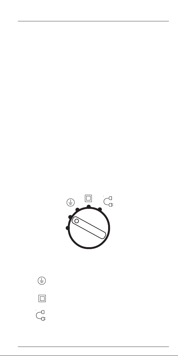
Rotary switch for selecting the type
of measurement
7
Page 8
Operating manual for the TG basic 1 appliance tester
6. Starting up
6.1. Initial equipping or battery replacement
The tester is operated using 6 x 1.5 V type AA batteries (IEC LR6)
or six type AA rechargeable batteries.
The six batteries supplied must be inserted into the tester before
starting the device.
Proceed as follows to insert the batteries:
- Switch off the device (rotary switch in the „OFF“ position)
- Release the screw from the battery cover
- Lift the cover from the lower part of the case
- Remove the old batteries if necessary
- Insert the batteries into the correct locations in the
battery compartment (taking care to ensure correct
polarity)
- Click the battery cover into place in the lower part of the
case and secure it by tightening the screw
6.2. Switching the tester on and off – Selecting the
measuring sequences
The tester is operated via a rotary switch and a „Start“ button.
EIN
ON
AUS
OFF
Measurements for devices with protective
conductor (PC I)
Measurements for devices without protective
conductor (PC II)
Measurements for testing the device connection
and extension cable (LPR)
GOSSEN Müller & Weigert
8
Page 9
Operating manual for the TG basic 1 appliance tester
„OFF“ switch position:
Turning the rotary switch to the „OFF“ position switches off the
device.
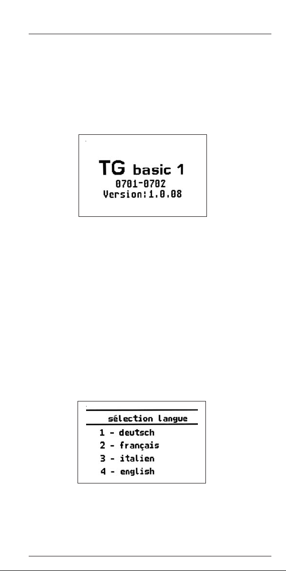
Turn the rotary switch to the „ON“ position to switch on the tester.
The device performs a self-test. If the device is OK, the following
switch-on message appears in the display:
Note that no other functions are available until the switch-
&&
&
&&
on message is displayed!
Selecting the menu language
To select the menu language, turn the rotary switch to the „ON“
position and press the „Start“ button.
The display shows the following menu.
The desired language is selected by briefly pressing the „Start“ button
(< 2 s). The respective number before the language designation
blinks to indicate the currently selected language. Pressing the „Start“
button for a longer time (> 2 s) confirms the currently selected
language and exits the language selection.
GOSSEN Müller & Weigert
9
Page 10

Operating manual for the TG basic 1 appliance tester
After the switch-on message has been displayed, the desired
operating mode PC I, PC II or cable test can be selected.
The „Measuring sequence“ window is displayed depending on the
setting of the rotary switch.
Briefly pressing the „START“ button starts the selected measuring
sequence.
Pressing the „START“ button for a longer time (> 2 s) calls up a
quick guide for the select measurement type.
Briefly pressing the „START“ button pages forwards through this
quick guide.
The scrollbar at the left provides an indication of how many
pages are available in the quick guide.
Help window (example)
Pressing the „START“ button for a longer period of time returns
you to the „Measuring sequence“ window.
If a measuring sequence is not started within a period of 3
minutes then the tester automatically switches off.
To switch the tester on again, the rotary switch must first be set to
the „OFF“ position and then back to the „ON“ position (normal
switch-on procedure).
GOSSEN Müller & Weigert
10
Page 11

Operating manual for the TG basic 1 appliance tester
7. Explanation of terminology
7.1. Protection class I (PC I)
The active parts of the device are protected against direct
touching by the basic insulation.
Through connection of the touchable conductive housing parts to
the protective conductor, these are included in the protective
measure in the case of direct touching (fault protection) with the
system.
The device has a protective conductor connection (earthed plug).
7.2. Protection class II (PC II)
The active parts are separated by strengthened or double
insulation (basic insulation and additional insulation). This
ensures protection against direct contact.
Protection against indirect contact also exists, since an insulation
fault is practically impossible. Such devices can nevertheless
have touchable metallic housing parts. Devices of protection class
II have a mains plug without an earth contact.
7.3. Protection class III (PC III)
Devices of protection class III are exclusively connected to
protective extra-low voltage electric circuits.
The protection against dangerous body currents is achieved by
the low voltage and the safe separation from other electric
circuits.
7.4. Protective conductor resistance (RPE)
Resistance between any conductive touchable parts, connected
to the protective conductor for protective purposes, and the
earthed contact of the mains plug, the device plug or the
protective conductor, which is constantly connected to the mains
power supply.
See also the measuring principle circuit under point 8.2.
&&
&
&&
7.5. Insulation resistance (R
This is the Ohmic resistance between conductive parts separated
by insulation.
Measurements are taken between the active parts and the body
as well as touchable conductive parts that are not connected to
the protective conductor.
See also the measuring principle circuit under point 8.3.
&&
&
&&
GOSSEN Müller & Weigert
)
ISO
11
Page 12

Operating manual for the TG basic 1 appliance tester
7.6. Substitute leakage current (IEA)
Current that would flow through the interconnected active
conductors of the device (test object) and the protective
conductor or the touchable conductive parts at rated voltage and
rated frequency of the device.
This measuring method determines the leakage current without
mains voltage.
It is an alternative measuring method for determining protective
conductor current or touch current.
See also the measuring principle circuit under point 8.4.
&&
&
&&
7.7. Visual inspection
Testing in accordance with DIN VDE 0701-0702 requires a visual
inspection of the device. According to the standard, the devices
should be inspected for external defects (without opening the
device) and, as far as possible, for suitability to the place of
installation.
(More details are provided in the DIN VDE 0701-0702 standard).
GOSSEN Müller & Weigert
12
Page 13

Operating manual for the TG basic 1 appliance tester
8. Conducting tests in accordance with
DIN VDE 0701-0702 Definition of standards
The sequence of tests is specified in the standard.
8.1. Visual inspection
The test objects are inspected for externally visible defects.
8.2. Measuring the protective conductor resistance
(for devices of protection class I)
The limit value is:
≤≤
Ω Ω
≤ 0.3
Ω for devices with connecting cables up to 5 m,
≤≤
Ω Ω
plus 0.1
1.0
Measuring principle circuit
Protective conductor resistance PC I
Ω Ω
Ω for every extra 7.5 m, up to a maximum of
Ω Ω
ΩΩ
Ω.
ΩΩ
Appliance tester
´Probe´
socket
Test line
Test socket
8.3 Measuring the insulation resistance
The limit value is:
ΩΩ
1 M
Ω for devices of protection class I
ΩΩ
ΩΩ
2 M
Ω for devices of protection class II
ΩΩ
ΩΩ
0.3 M
Ω for devices of protection class I (with switched-on
ΩΩ
heating elements)
1)
Also applies to touchable conductive parts of test objects
in protection class I that are not connected to the protective
conductor.
2)
If the required insulation resistance is not achieved in the
case of test objects in protection class I with heating
elements with a total capacity
nevertheless rated as faultless if the protective conductor
current does not exceed the limit values.
GOSSEN Müller & Weigert
2)
≥ 3.5 kW, the test object is
13
1)
Test object
Page 14

Operating manual for the TG basic 1 appliance tester
Measuring principle circuit
Insulation resistance PC I PC II
Appliance
tester
Test
object
´Probe´
socket
T est line
Test socket
´Probe´
socket
T est line
T est socket
8.4. Measuring the substitute leakage current for devices of
protection class I
The substitute leakage current procedure is an alternative method
for measuring the protective conductor current.
The limit value is 3.5 mA.
The substitute leakage current for test objects with heating
elements having a total connected power greater than 3.5
kW must not be greater than 1 mA/kW heating power, up to
a maximum value of 10 mA.
Measuring principle circuits
Substitute leakage current procedure PC I
GOSSEN Müller & Weigert
Appliance
tester
T est socket
T est object
14
Page 15

Operating manual for the TG basic 1 appliance tester
8.5. Measuring the substitute leakage current for devices of
protection class II
The substitute leakage current procedure is an alternative method
for measuring the touch current.
The limit value is 0.5 mA.
Measuring principle circuits
Substitute leakage current procedure PC II
Appliance tester
´Probe´
socket
T est line
Test socket
Test object
8.6. Inspecting the inscriptions
Safety-related inscriptions must be controlled and, where
necessary, renewed or supplemented in suitable form.
GOSSEN Müller & Weigert
15
Page 16

Operating manual for the TG basic 1 appliance tester
9. Test procedures
9.1. Testing devices of protection class I
Rotary switch position:
Test object connection:
The test procedure occurs automatically in the sequence
specified below:
- Protective conductor resistance
- Insulation resistance
- Substitute leakage current
Please note: The test object must be switched on.
&&
&
&&
The test sequence is started by pressing the „Start“ button
for < 2 s.
9.1.1. Measuring the protective conductor resistance
The protective conductor resistance is measured using a
measuring current > 200 mA DC. The direction of current is
automatically reversed by the tester.
The measuring sequence is indicated on the display as follows:
Exceeding of the limit value is indicated as follows:
- The momentary measurement value blinks
- An audio signal is emitted
33
A „
3“ is shown in the assessment field if the measurement does
33
not reach the limit value.
GOSSEN Müller & Weigert
16
Page 17

Operating manual for the TG basic 1 appliance tester
At the start of measuring, the tester checks to see if the
measuring current is greater than 200 mA. If this is not the case,
the test is aborted.
This can occur for the following reasons:
- The test object is not of protection class I
- The test object is not connected to the tester or the test
line is not connected
- The protective conductor has an open-circuit
This is indicated by a scrolling message in the status line.
The tester performs the following checks:
a)Check of the test wiring!
The measurement procedure is continued when the
missing connection to the test line or test object is
restored and the measuring current is > 200 mA.
b)Check that the appliance conforms to
protection class I!
If the tester detects that the appliance does not
conform to protection class I, then the test must be
aborted by pressing the „START“ button.
If the test wiring is „OK“ and the test object conforms to protection
class I, then the protective conductor connection has an opencircuit or high resistance. The test must be aborted by pressing
the „START“ button.
When the test is aborted, the assessment window is shown in the
display.
Measurement of the insulation resistance and substitute leakage
current is not performed.
This also applies when the measured protective conductor
resistance is > 1 Ω .
GOSSEN Müller & Weigert
17
Page 18

Operating manual for the TG basic 1 appliance tester
When performing the protective conductor resistance
measurement, the automatic test sequence can also be switched
to a permanent measurement (max. 3 min).
When the tester is in the normal measuring mode, pressing the
„START“ button switches the tester into the permanent
measurement mode.
The bar graph is then no longer shown in the display.
Pressing the button again continues the measurement with a
reversed test current polarity. Pressing the button again ends the
protective current measurement and continues with the next
measurement in the measuring sequence.
During permanent measurement, the connecting cable of the test
object should be moved, section by section, along its whole
length, in order to find broken conductors or weak points. The
momentary measurement values are continuously acquired and
displayed by the tester. The maximum measurement value is
stored and displayed in the assessment window at the end of the
measuring sequence.
9.1.2. Measuring the insulation resistance
The insulation resistance is measured automatically. Switching to
permanent measurement is not possible.
Failure to reach the limit value is indicated as follows:
- The momentary measurement value blinks
- An audio signal is emitted
33
A „
3“ is shown in the assessment field if the measurement
33
exceeds the limit value.
GOSSEN Müller & Weigert
18
Page 19

Operating manual for the TG basic 1 appliance tester
9.1.3. Measuring the substitute leakage current
The substitute leakage current is measured automatically.
Switching to permanent measurement is not possible.
Exceeding of the limit value is indicated as follows:
- The momentary measurement value blinks
- An audio signal is emitted
33
A „
3“ is shown in the assessment field if the measurement does
33
not reach the limit value.
9.1.4. Test assessment
When the automatic test sequence finishes, an assessment
window is displayed.
The measurements and their assessments („X“ or „
displayed here.
The status bar displays „Test OK“ or „Test n. OK“ depending on
the result.
Briefly pressing the „START“ button will repeat the test or perform
a new test if a new test object has been connected. Pressing the
„START“ button for longer than 2 s will display the quick guide
(see point 6.2.)
GOSSEN Müller & Weigert
19
33
3“) are
33
Page 20

Operating manual for the TG basic 1 appliance tester
9.2. Testing devices of protection class II
- Testing devices without a protective conductor and with
touchable conductive parts
- Testing devices with a protective conductor and with
touchable conductive parts that are not connected to the
protective conductor
Caution:
With these appliances, this test can only check the
&&
&
&&
insulation resistance and the substitute leakage current
between the touchable electrical components that are not
connected to the protective conductor and the L and N
connections.
Testing of the protective conductor resistance and the
substitute leakage current relating to the protective
conductor must first be performed after the measuring
sequence for protection class I appliances.
Rotary switch position:
Test object connection:
The test procedure occurs automatically in the sequence
specified below:
- Insulation resistance
- Substitute leakage current
The test object must be switched on (mains switch).
&&
&
&&
The test sequence is started by pressing the „Start“ button
for 2 s.
9.2.1. Measuring the insulation resistance
The same statements apply as in point 9.1.2.
9.2.2. Measuring the substitute leakage current
The same statements apply as in point 9.1.3.
GOSSEN Müller & Weigert
20
Page 21

Operating manual for the TG basic 1 appliance tester
9.2.3. Test assessment
The measurements and their assessments („X“ or „
displayed here.
The status bar displays „Test OK“ or „Test n. OK“ depending on
the result.
Briefly pressing the „START“ button will repeat the test or perform
a new test if a new test object has been connected.
Pressing the „START“ button for longer than 2 s will display the
quick guide.
9.3. Cable test
The cable test allows testing of IEC cables (appliance connection
cables with non-heating device connections), distribution boxes
and extension cables.
Rotary switch position:
33
3“) are
33
The IEC connection line
The test procedure occurs automatically in the sequence
specified below:
- Measuring the protective conductor resistance
- Measuring the insulation resistance
- Cable test
GOSSEN Müller & Weigert
21
Page 22

Operating manual for the TG basic 1 appliance tester
9.3.1. Protective conductor resistance
The same statements apply as in point 9.1.2.
9.3.2. Insulation resistance
The same statements apply as in point 9.1.3.
9.3.3. Cable test
This test provides an additional function that is not part of the DIN
VDE 0701-0702 standard.
This test checks a connection cable or extension cable for opencircuits in the live (L) and neutral (N) conductors and for shortcircuits between L and N.
Cable test assessment window:
Line opencircuit
Line shortcircuit
Line OK
Briefly pressing the „START“ button will repeat the test or perform
a new test if a new test object has been connected. Pressing the
„START“ button for longer than 2 s will display the quick guide.
GOSSEN Müller & Weigert
22
Page 23

Operating manual for the TG basic 1 appliance tester
9.4. Measuring the voltage at an external earthed mains
socket
The test allows checking of the voltage potentials between the
L→N, L→PE and N→PE terminals. The L→PE and N→PE
display depends on the position of the live conductor in the
earthed mains socket (right or left).
To perform the measurement, plug the IEC line provided with the
tester into the IEC socket of the tester.
The rotary switch must be in one of the following positions.
The measuring process starts automatically if voltage is present
at the socket.
EIN
ON
The measuring process starts automatically if voltage is present
at the socket.
Only the voltage potentials between the connection
&&
&
&&
terminals are measured. The measurement provides no
information as to whether the earthed mains socket has
been correctly installed.
No warning message is provided if a dangerous touch
&&
&
&&
voltage exists on the PE conductor.
GOSSEN Müller & Weigert
23
Page 24

Operating manual for the TG basic 1 appliance tester
10. Checking the battery voltage
Before each measurement, the tester automatically checks that
the charge level of the batteries is sufficient for correct execution
of the respective measurement.
If this is not the case, the following information is displayed:
In this case the tester must be switched off and the batteries
replaced as described in point 6.1.
11. Technische Daten
Protective conductor resistance:
Measuring range: 0.1…2.000
Display range: 0.05…2
Resolution: 0.001
Tolerance:
±±
± (5% + 2 digits)
±±
Measuring current/voltage: min.
ΩΩ
Ω
ΩΩ
ΩΩ
Ω
ΩΩ
ΩΩ
Ω
ΩΩ
±±
± 200 mA DC / > 4 V
±±
Insulation resistance:
Measuring range: 0.1…20 M
Display range: 0.1…20 M
ΩΩ
Ω
ΩΩ
ΩΩ
Ω
ΩΩ
Resolution:
im Bereich 0.1…9.999 M
ΩΩ
Ω
ΩΩ
im Bereich 10.00…20.00 M
Tolerance:
ΩΩ
Ω
ΩΩ
≥≥
≥ 0.001 M
≥≥
≥≥
≥ 0.01 M
≥≥
±±
± (5% + 2 Digit)
±±
ΩΩ
Ω
ΩΩ
ΩΩ
Ω
ΩΩ
Measuring voltage/current: min. 500 V DC / >1 mA
Substitute leakage current:
Measuring range: 0.1...20 mA
Display range: 0.1...20 mA
Resolution:
Range 0.1…9.999 mA
Range 10.0 …20.00 mA
Tolerance:
≥≥
≥ 0.001 mA
≥≥
≥≥
≥ 0.01 mA
≥≥
±±
± (5% + 2 Digit)
±±
Measurement voltage: approx. 32 V AC
GOSSEN Müller & Weigert
24
Page 25

Operating manual for the TG basic 1 appliance tester
Spannungsmessung an externer Schutzkontaktsteckdose:
Measuring range: 50…270 V AC
Display range: 50...270 V AC
Resolution: 1 V
Tolerance:
±±
± 5 %
±±
General technical data:
Power supply: 6 x 1.5 V batteries
Typ IEC LR6 (AA)
6 x 1.2 V NiMH
rechargeable batteries
Degree of pollution: 2
Overvoltage category: CAT II 300 V
Protection degree: IP40
Protection class: II
Electrical safety: EN61010-1/VDE0411
DIN VDE 0404 Parts 1,2
DIN VDE 0413, Parts 1,2,4
EMC emission: EN61000-6-3
EMC interference resistance: EN61326-1
Dimensions (L x W x H): Approx. 265 x 110 x 50 mm
Weight: Approx. 700 g
12. Notes on cleaning
When dirty, the tester is to be cleaned with a dry cloth (no
solvents) or an anti-static cloth.
The tester must be protected from shock and impacts.
13. Calibrating the tester
According to the DIN VDE 0701-0702:2008-06 standards:
„Measuring devices used for testing must be regularly
checked and calibrated.“
We recommend a calibration interval of one year. Shorter periods
are recommended if the tester is frequently used or used under
tough conditions. If the tester is seldom used then the calibration
interval can be extended up to a maximum of 3 years.
GOSSEN Müller & Weigert
25
Page 26

Operating manual for the TG basic 1 appliance tester
GOSSEN Müller & Weigert
26
Page 27

Operating manual for the TG basic 1 appliance tester
GOSSEN Müller & Weigert
27
Page 28

Operating manual for the TG basic 1 appliance tester
14. Manufacturer’s guarantee conditions
The TG basic 1 appliance tester is subject to a strict quality
inspection. Nevertheless, we grant a 24-month manufacturer’s
guarantee in the case of malfunctions during normal daily usage.
Manufacturing or material faults will be remedied, free of charge,
as long as the tester shows no signs of third party actions and is
unopened before it is sent back to us.
Damage resulting from the device being dropped or mishandled is
excluded from guarantee claims.
GOSSEN Müller & Weigert
GOSSEN Müllert & Weigert
Kleinreuther Weg 88
D-90408 Nuremberg, Germany
Phone +49(0)911 / 3502-0
FAX +49(0)911 / 3502-307
info@g-mw.de www .g-mw.de
Item: 2786688238 10.2011
 Loading...