


USER`S MANUAL
Thermal Graphics Printers
IPP 144 - 40 G
IPP 144 - 40 GE
Paper Reroll Mechanism
IPP - AW

Safety instructions (EN 61010-1)
In order to preclude any danger to the operator, the following instructions
should be followed:
a) In case any damage or malfunction is detected, take the unit out of operation without delay.
b) Before disassembling the unit, disconnect all inputs / outputs and the supply voltage. When
mounting the unit and the connections, make sure all live components are protected from
being touched directly.
c) Comply with the usual regulations and safety provisions for low and high current systems, in
particular country-specific safety provisions (e.g. VDE 0100).
d) The maximum admissible potential existing between the pin groups as well as to the external
protective conductor must not be exceeded. Refer to the unit´s identification label.
e) When connecting the unit to other devices (e.g. PCs), the connection must be carefully
planned. Internal connections in external units (e.g. GND connected to protective earth) may
cause excessive voltage potential.
f) This device must be grounded! For low voltage 12VDC and 24V
Units with a.c. supply voltage must be connected the protective conductor.
g) Make sure that the unit is property mounted before connection and power on !
In order to preclude any damage to the unit, the following items must be
taken into account:
The maximum admissible potential between the pin groups must not be exceeded.
This applies in particular to high voltage tests.
Refer to the instruction manual !
systems use screened cable.
DC
Warning: Hazardous live voltage !
WARNING:
There is always hazardous voltage present in certain parts during the operation of electrical equipment.
Non-observance of the safety instructions can result in severe personal injury or damage to property. Only qualified personnel should
work on this equipment. The successful and safe operation of this equipment is dependant on proper transport, storage, set-up,
installation and careful operation and maintenance.
QUALIFIED PERSONNEL
Are personnel who are familiar with the set-up, installation, commissioning and operation of the product and have the qualifications
corresponding to their activities, e.g.:
- Are trained and authorised to energise, de-energise, clear, ground and tag circuits and equipment / systems in accordance with
established safety standards.
- Are trained in the proper care and use of protective equipment in accordance with established safety practices.
- Are trained in first aid.
Safety according to EN 61010-1, VDE 0411
CAT III > 150 V [ 300 V
Pollution degree : 2; indoor use; altitude <2000 m; relative humidity <80 % up to 31 °C;
T emperature: 5 °C to 40 °C;

Table of Contents
page
I. IPP 144 - 40 G / IPP 144 - 40 GE 3 - 60
1. General Features 3 - 5
2. Technical Data 6 - 9
2.1. Basic Version 6 - 8
2.2. Version E 9
3. Design and Installation 10 - 11
4. Connection 11 - 17
4.1. Pin assignment 11 - 13
4.2. Interface selection 14
4.3. Connecting Diagram serial 15 - 17
5. Operation 18 - 23
5.1. Operating Controls 18 - 19
5.2. Replacing the paper roll 20
5.3. Menu program 21 - 23
6. Adjustments 24 - 29
6.1. General Functions 24 - 25
6.2. Serial Interfaces 25 - 26
6.3. Date / Time 26 - 28
6.4. Date / Time Output 28 - 29
7. Functional Description 30 - 35
7.1. Start Printing 30
7.2. Addressing 30 - 31
7.3. Handshakes Messages 31 - 33
7.4. Version E (IPP 144-40 GE) 33 - 35
7.4.1. Texts Entry 33 - 34
7.4.2. Texts Output 35
page
8. Appendix 36 - 56
8.1. Menu program complete Selection 36 - 37
8.2. Character Sets 38 - 40
8.3. Details of Printer Control 41 - 53
Commands
8.3.1. Short View of Control
Commands 41
8.3.2. Print Character Commands 41 - 44
8.3.3. Print Position Commands 44 - 45
8.3.4. Bitmap image Commands 45 - 49
8.3.5. Line Feed Commands 49
8.3.6. Barcode Commands 50 - 53
8.4. Connection Examples
for GMW instruments 54 - 55
8.4.1. Connection with DPM / MF 54
8.4.2. Coupling with DAA 55
8.5. Examples for Automatic
Text Insert Mode 56
II.Paper Reroll
Mechanism IPP - AW 57 - 60
1.General information 57 - 58
Design / Installation 58
2.Technical data 59
3.Operation 60
III. Accessories 61
1

Index
page
Accessories 61
Addressing 26, 30
Addressing & protocol / text 31
Basic version 5
Baudrate 25
Barcode Commands 50
Bitmap image Commands 45
Character set 24, 38
Connection diagrams 11
Connection Examples 54
Control characters 38
Data format - serial 25
Date / time - output via interface II 28
Date / time - setting 26
End of paper indication 18
Environmental conditions 7
Enhanced version (E - version) 5
Graphic print-out directly 19
from WINDOWS®
Handshake serial - RTS / DTR 31
Handshake serial - XON / XOFF 32
Headline data & time 29
Input buffer 7
Installation 10
Interface selection 14
Key LINE FEED / ENTER 18
Key lock 19
Key MENU / SELECT 18
KEY RESET 19
Line Feed Commands 49
Line with (character per line) 24
Mechanical data 8
Menu program - complete selection 36
Menu program - entry 21
Menu program - quitting 22
Model types 4
page
Operating controls, general 18
Paper 6
Paper reroll mechanism 57
Parameters, changing 22, 23
Parameters, printing the current 21
Parity 25
Pin assignment current loop 16
Pin assignment - interface I 15
Pin assignment - interface II 17
Print Character Commands 41
Print Control Commands 40
Print format 24
Print interval - serial 32
Print interval - setting 24
Print mechanism 6
Print Position Commands 44
Protocol - serial 29
Replacing the paper roll 20
Snap lock 18
Software version 8
Start printing 30
Technical Data 6
Text adding, overwrite 33
Text call with measured data, serial 34
Text - deleting 33
Text entry 33
Text entry - block 34
Text entry - wildcards 28
Text output 35
Voltage supply 7
Wildcards for measure value 34
Windows programming software 5
2

I. IPP 144 - 40 G / IPP 144 - 40 GE
1. General Features
The Thermal Graphics Printer IPP 144-40 G (Industrial Process
Printer) is a device designed for outputting text, data and
graphics, i.e. measured value, machine and process states, error
messages, production data, etc.
T wo application examples:
.
If connected to a digital voltmeter , the IPP 144-40 G records
the measuring values (with date/time for the E version).
.
Its integrated interface allow the use of the IPP 144-40 G as
a peripheral for all PLCs (RS 232 C; RS 422; RS 485; USB;
Profibus DP).
The Thermal Graphics Printer is a DIN size panel mounting unit
which is able to print line widths of up to 48 characters per line.
The 14m paper roll (commercial grade document proof thermal
paper) is located inside the housing and can be easily replaced
by means of a swivel type front panel. Án end of paper indicator
lights up if the printer runs out of paper .
3
Each printer is addressable, which allows the connection of
up to 31 devices to one sender device via a data line at the
RS 485 interface, e.g. to a PLC.
Review of the
model types
Model
IPP 144-40 G
IPP 144-40 GE 232
IPP 144-40 GE 485
IPP 144-40 GE PB
IPP 144-40 GE USB
There are two version of the printer: The Basic V ersion
IPP 144-40 G with the interface I and the Enhanced V ersion
IPP 144-40 GE with the interfaces I and II.
There are three option for the voltage supply: 12V DC (10V ...19V
DC) or 24V DC (19V ...36V DC) or 1 10V/230V AC (switch-mode
power supply: 85V ...265V AC)
There are four option for the interface IIl :
RS 232 C, RS 485, ProfiBus or USB
Supply Voltage
12V DC 24V DC 110/230V AC
12V DC 24V DC 110/230V AC
12V DC 24V DC 110/230V AC
12V DC 24V DC 110/230V AC
12V DC 24V DC 110/230V AC
Interface I
Yes
Yes
Yes
Yes
Yes
The connector for the interface II of RS 232 C, RS 485 and
ProfiBus is a 9 pin D-Sub-socket. It is possible to change this
interface card in the factory . The interface option USB has a
special USB-B-socket. It is not possible to change this
interface card with the other cards. Special adapter cables
and converters are used in this situation.
4

WindowsProgramming
software
A Windows-Programming software has been developed.This
software will be available to progam the GE text memory , transfer
user defined fonts or symbols and set the printer configuration
parameters. Also this software package includes actual
Windows printer drivers.
The software will be on CD-ROM.
Basic Version
IPP 144-40 G
Enhanced
Version
IPP 144-40 GE
The basic version IPP 144-40 G provides one serial interface
capable of receiving only. Return (handshake) messages to
the sender are sent via hardware line. Texts and measuring
value to be printed must be transmitted from the sender device
since the basic version does not have an internal text memory .
It is possible to print with the basic version bitmap image and
barcodes. The bitmap image files and the barcode files are
generated with printer control commands in a terminal emulation
program.These files are transmitted by interface I to the
printer. It is possible to download this file onto the font ROM
chip in the printer. For the printer control commands and
download commands see section 8.3. in this manual.
Note: The cyrillic character set is on the font ROM chip.
If user defined fonts or symbols are downloaded onto the font
ROM chip, the cyrillic character set will be overwritten, and
the cyrillic character set will no longer be available.
The enhanced version IPP 144 - 40 GE provides a second,
bi-directinal serial interface capable of outputting return
messages under program control in compliance with a protocol.
In addition, this model includes a text memory capable of
storing up to 15 texts which are called by specifying the
corresponding text number. Moreover, date and time may be
printed with texts and data.
The printer interfaces of the IPP 144-40 GE can be set in the
menu program as serial transfer or standard Windows printer
drivers. So it is possible to print data (e.g.user defined fonts
and symbols) directly with Windows.
It is not possible for the user to upgrade the basic version to
the enhanced version; as this is a different factory version.
5

2. Technical Data
2.1.Basic Version
Print
mechanism
Paper
Type of printing Fixed head thermal line
Character representation 576 dots/line, 8 dots/mm
Print speed approx. 15 line/s (standard text mode)
Character/line 48 characters
24 characters
16 characters
8 characters
Character height 3 mm at 48 characters
4 mm at 24 characters
9 mm at 16 characters
18 mm at 8 characters
Character sets ASC II, german,
french, danish,
norwegian,
swedish / finnish,
spanish, english, cyrillic
Service life min. 10x106 Impulse or 50 km
T yp e commercial grade,
document proof
thermal paper
Width 80 mm (+0 / -1 mm)
Length approx. 14 m
(approx. 4.600 line
up to 48 characters per line)
Max. outer roll diameter 40 mm
Min. inner roll diameter 1 1,5 mm
Temperature standard paper: 0 °C to 60 °C
6
Input buffer
Serial
Interface I
Serial 16 kB
T y p e RS 232 C; RS 422; RS 485
or Current loop
Baudrate 110; 150; 300; 600; 1200;
2400; 4800;9600;19200;
38400
Data format 7 bit / 8 bit
1)
Parity bit even, odd, mark, space, no
1)
Voltage
supply
Ambient
conditions
Standards
Safety acc. to EN 61010-1:2001
CA T III > 150 V ≤ 300 V
pollution degree 2
DC 10 V ... 19 V
approx. 20 V A
2)
19 V ... 36 V
approx. 18 V A
2)
AC 85 V ... 265 V , 45 - 65 Hz,
approx. 15 W
switch-mode power supply
Storage temperature range -20 °C to +60 °C
Operating temperature range 0 °C to +45 °C
Climate relative humidity < 80 %
up to 31 °C
Protection type acc. to EN 60529/VDE 0470
housing IP 50
terminals IP 00
Insulation group C acc. to VDE 0110
Mech. strength acc. to IEC 1010
EMC
Emission EN 5501 1, Class A
EN 55022, Class B
Susceptibility EN 61000-4-2 B
EN 61000-4-3 A
EN 61000-4-4 B
CE
1)
See setting transmission parameters of the sender at page 9.
2)
Starting current approx. 1,2 A (10 V ... 19 V) or approx. 0,8 A
(19 V ... 36 V).
This value can be used to rate the external fuse.
7

Connections
Voltage supply Screw type/terminals
fixed: 0,2 to 4 mm²
flexible: 0,2 to 2,5 mm²
AWG: 24 to 12
Interface I 9pin D-Sub socket
Interface II 9 pin D-Sub socket
or
USB-B socket
Connection for paper
reroll mechanism 4pin MASCON, MLAS
Connection for
Alarm relay output
Screw type/terminal
fixed: 0,2 to 4 mm²
flexible: 0,2 to 2,5 mm²
AWG: 24 to 12
normally open
50 V AC, 2 A
30 V DC, 2 A
Miscellaneous
8
Dimensions
(W x H x D) 144 x 72 x 159 mm
Switchboard mounting screws against rear side
of switchboard
Internal fuse
( on power supply board) 12V DC : T 3,15 A
24V DC : T 2 A
1 10V - 230V AC : T 2 A
This operating manual applies to software version
5.01.05 and higher

2.2. V ersion E
Serial
Interface II
Text entry for
texts to be
stored
Text memory
Internal clock
Warning !
T y p e RS 232 C or RS 485
1)
ProfiBus or USB
Baudrate 110: 150; 300; 600; 1200;
2400; 4800; 9600;19200;38400
Data format 7 bit / 8 bit
Parity bit even, odd, mark, space, no
2)
2)
separate configuration
by interface II
T yp e CMOS-RAM, battery buffered
3)
Battery life 10 years typical
Memory size 600 Byte = 15 texts
T yp e CMOS, battery buffered
Accuracy ± 10 ppm = 0,8 sec / day
1)
Please specify when ordering; if nothing is specified, RS 232 C is
supplied.
2)
See Setting transmission parameters of the sender
3)
Lithium battery: 3 V
type: VARTA CR 2/3 AA Typ 6237
PANASONIC BR 2/3 A 1 P
^
3)
^
This product contains a Lithium battery which must not be
cut open, incinerated, exposed to temperature above
+60 °C or recharged.
Dispose of in accordance with national regulations.
9

Design
3. Design and Installation
Front
10
1 Paper and cutting edge
2 Key: LINE / FEED / Enter
3 Key: MENU / Select
4 Alarm LED (paper end indicator)
5 Serial interface
Interface II (only version E)
6 Serial Interface I
7 Voltage supply
Make sure that the unit is properly
mounted before connection and power on.
8 Alarm contact
(paper end only version E)
9 Snap lock
10 Mounting screws
11 Protective conductor
connection. Must be
connected to ground.
12 Connection / paper reroll
mechanism IPP-AW
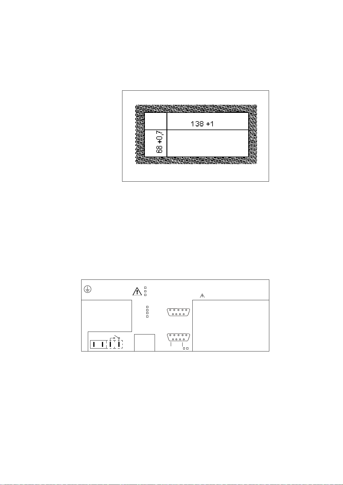
Installation
The IPP 144 - 40 G fits into a DIN standard panel cut out. It
is inserted into the switchboard opening from the front side
and is fixed against the switchboard rear using mounting
screws. The switchboard thickness must not exceed 12 mm.
4. Connection
4.1. Pin assignments
Pin
assignment
WARNING: This device must be grounded -ACHTUNG: Dieses Gerät muss geerdet werden !
IPP 144 - 40 G
Opt.: . . . . . . .
EN 61010 -1:2001 CAT III
.
CE
Alarm
-
+
LN
1
85 V...265 V AC; 45...60Hz ; 15W
19 V...36 V DC; 18 VA
10 V...19 V DC; 20 VA
Interface II
RS 232 C
RS485
Profi Bus
USB
IPP-AW
Interface I
5
5
Sig GND
9
Sig GND
RXD (-
)
9
TXD
RTS
DTR
CLA
+5Vis
RTS
RTS
DTR
RXD
GND
1
6
GND
RXD (+)
1
6
DTR
Serien Nr.:
Serial No.:
No.de serie
Lithium battery inside ( VERSION E )
TXD
Connect the unit as shown in the connection diagramms.
Observe all national safety regulations, especially for the supply power
connections.
11

Serial
Interface I
Pin Signal
1 GND Ground (shield)
2 RXD (+) Receive data
3 +5 V Output +5 V / 20 mA
4 n.c.
5 RXD (-) Signal ground
6 DT R Open collector; active if
DTR is +8 V
12
7 DT R (Data Terminal Ready)
+8 V: ready to receive
-7 V: not ready to receive
8 RTS (Request To Send)
+8 V: ready to receive
-7 V: not ready to receive
(text buffer is full)
9 RTS Open Collector; active if
RTS is +8 V
The serial interface I has been designed to allow the
implementation of all widely used interfaces:
RS 232 C; RS 422; RS 485 and Current loop.
See chapter 4.3.: Connecting diagram

Serial
Interface II
(only
IPP 144 -40 GE)
Pin Signal
1 G ND Ground (shield)
2 RXD (+) Receive data
3 n.c.
4 TXD Transmit data
5 RXD (-) Signal ground
6 n.c.
7 D T R (Data T erminal Ready)
+8 V: ready to receive
-7 V: not ready to receive
8 R TS (Request T o Send)
+8 V: ready to receive
-7 V: not ready to receive
9 n.c.
This interface can either be operated under hardware
handshake (DTR, RTS) or software handshake
(XON / XOFF - Protocol). This does not require special
settings.
See chapter 4.3.: Connecting diagram
13

4.2. Interface selection (Interface I)
Slide snap lock to the right hand side, swivel front door out.
Now you can see the switch S 101 on the printed circuit
board.
- For RS 232 C, RS 422 and RS 485 set switch S 101
to the right hand side.
- For Current loop, set switch S 101 to the left hand
side.
14
IMPORTANT:
This switching only applies to interface I.
If the printer is connected to the sender device
(e.g. to a PLC) the interface parameters must be
matched to those at the sender device.
See chapter 6.2. which describes the setting of
the baudrate, data format, stop bit and parity bit.
RS 232 C
RS 422
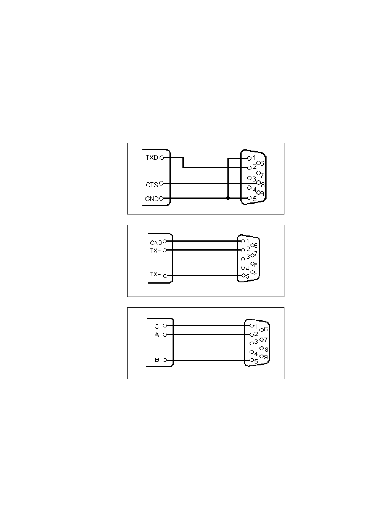
4.3. Connecting diagram
Interface I
Set slider switch S 101 to the right hand side !
(see „Interface selection“ 4.2.)
RS 485
Sender IPP 144
See explanation on page 17
15
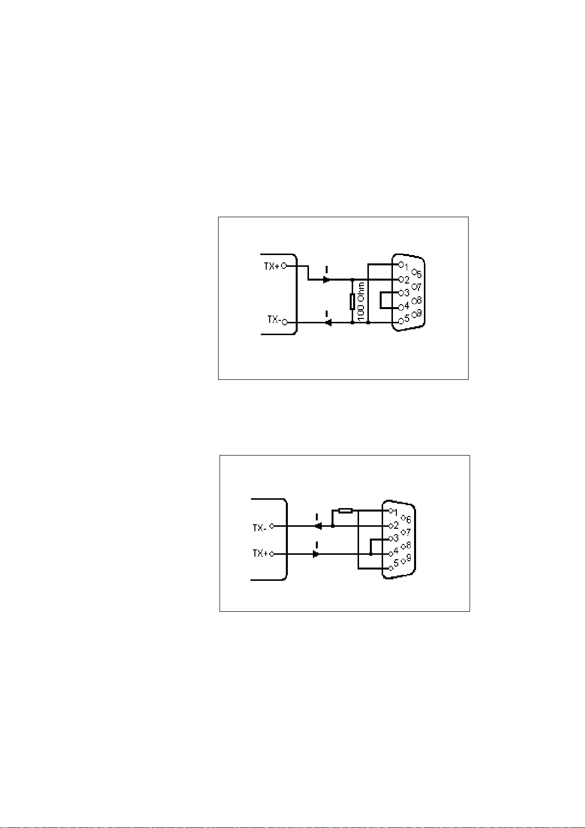
Current loop
Sender active,
IPP 144 - 40 G
passive
Sender passive
IPP 144 - 40 G
active
Set slider switch S 101to the left hand side !
(see „Interface selection“ 4.2.)
Sender active IPP 144-40G passive
Sender passive IPP 144-40G active
16
100 Ohm
„I“identifies the direction in which the current flows (20 mA)
RS 232 C
RS 485
(Option)
ProfiBus
(Option)
Interface II
USB
(Option)
Sender / receiver IPP 144-40 GE
Explanation concerning the signal names underRS 485.
The names A, B, C correspond to the EIA 485 - Standard:
inactive or logical „1“; A > B
logical „0“: B > A
If an interface does not comply with that standard, the
connections of A and B must be interchanged.
Standard USB chassis socket type B
pin 1 +5V
pin 2 U SBD M
pin 3 USBDP
pin 4 G N D
17

5. Operation
5.1. Operating Controls
The numbers with the operating controls refer to the
diagrams in chapter 3.
LED
„Alarm“
(4)
LINE FEED /
ENTER
(2)
The ALARM LED has two functions.
1. T o indicate „end of paper“ or „no p aper“
2. To indicate the front door is open
Examples:
1. The front door is closed.
If this LED is lit, the printer has run out of paper . Insert a
new paper roll; see section 5.2. „Replacing the Paper Roll“.
the front press-button switches (LINE FEED & MENU keys)
are deactivated.
2. The front door is open.
The LED is lit. Printing may continue until the input buffer is
empty , and then the data transmission goes to st andby.
3. The front door is open and the printer has run out of
paper .
The LED lit. The printer stops printing and the front pressbutton switches are deactivated.
After replacing the paper roll the front press-button
switches are active. The ALARM LED remains ON until the
front door is closed. The printer can start working.
This key has two functions:
LINE FEED:
During operation used for manual paper feed.
In the menu program it is used to accept and save
the parameters selected via „Select“.
MENU /
SELECT
(3)
18
This key has two functions:
MENU:
If during operation this key is pressed continuously
for more than 3s, the printer switches to menu
program mode in which device parameters are printed
out and can be modified.
Select:
Within the menu program it is used for selecting the
device parameters.

Paper cutting
edge
(1)
In order to tear off the paper , pull the paper quickly
sideways and up.
Snap lock
(9)
Locking the
Menu / Select
key
RESET -key
Push this to the right hand side to open the front panel in
order to be able to replace the paper roll or to set the slider
switch S 101 which is used to set the desired interface (see
chapter 4.2. „Interface selection“) or to set the RESET
switch S 102.
If the jumper B is connected, the „MENU / SELECT“ key
is locked; menu parameters can neither be printed or
modified.
In order to print or modify parameters:
remove jumper B !
The key S102 resets the printer to the standby mode. The
menu parameters will not to be changed.
19

5.2. Replacing the Paper Roll
Proceed as described below:
1. For devices with a.c. powersupply be very careful.
Warning: Dangerous voltage
is accessible if replacing the paper roll after
opening of the front panel !
2. Push the snap lock to the right hand side and open the
front panel.
3. Tilt the wire frame upwards;
remove the old paper roll.
4. Insert new paper roll; make sure it rotates clockwise
during printing (see left side of the figure).
5. Trim the leading edge of the paper roll to get a clean
straight edge (see right side of the figure). Insert
paper into bottom of print mechanism (as shown in the
diagram below) until roller automatically takes it up.
6. Press the „LINE FEED / ENTER“ key until the paper
appears at cutting edge.
20
7. If you have fed too much paper , carefully rewind the roll.
push the wire frame back over the roll.
8. Close the front panel (snap lock must lock). The Alarm
LED extinguishes and the printer is ready .

5.3. Menu Program
All functions of the IPP 1444 are set via menu program
using the „ENTER“ and „SELECT“ keys and are saved when
the user quits the program.
From then the IPP 144 automatically uses these
parameters.
The print format for the printout of the parameters is always
NORMAL with 48 character per line, so that the parameters
can be read during printing.
The possible setting are explained in chapter 6.
Entering
the menu
program
Print current
parameters
Press the „MENU / SELECT“ key for approx.
3 seconds.
The IPP 144 reacts by printing
„ACTUAL P ARAMETRS ? PRESS „ENTER“
Press the „ENTER“ key,
the IPP 144 prints the currently set parameters.
The final printout says
„CHANGE P ARAMETERS ?“
21

The menu
program
„Change
Parameters“
Press „ENTER“ and „SELECT“ simultaneously
for approx. 4 seconds; the IPP 144 brings up
the first function which can be modified.
(see changing parameters)
The menu program „Change Parameters“ can be called in
one of two ways:
Quitting
the menu
program
If there are no keys pressed over a period of approximately
2 minutes, the program is terminated automatically and
any modifications made are not saved.
Without prior printing of the current parameters:
Press both keys following
„ACTUAL P ARAMETERS ? ...“.
With prior printing of the current parameters:
Press both keys following
„CHANGE P ARAMETERS ?“.
The program is terminated by simultaneously
pressing „ENTER“ and „SELECT“
Following the printout
„END“
all modified functions are saved.
22

Changing
parameters
The IPP 144 prints one of the changeable
parameters
Press „ENTER“ to accept the parameter and
to move to the next function.
Press „SELECT“ to display the next
parameter option.
Example:
SET BAUDRATE NO ?
„SELECT“ „ENTER“
YES ?
„ENTER“
BAUDRA TE 300
300
„SELECT“
600
„ENTER“
>>> 600
TO STORE BAUDRA TE; PLEASE PRESS „ENTER“
SET BAUDRA TE AGAIN, PLEASE PRESS „SELECT“
„ENTER“
SET DA T A FORMA T NO ?
In case
1: Baudrate 600 (Baud) 2: Baudrate 300 (Baud)
is saved is saved
23

6. Adjustment
6.1. General Functions
The various functions and device parameters are selected
and set via the menu program (see chapter 5.3.).
The appendix contains a summary .
PRINT
FORMA T
CHARACTER /
LINE
NORMAL: The printout can be read during printing, the
INVERSE: The printout is made top down, the last print
line is at the bottom. In this case the
printout is in the proper chronological order
after the paper has been torn off.
Print formats can be switched via the serial interface (see
appendix 8.2. „additional control characters“), if the input
buffer is empty!
90-degree rotation: It is possible to set the printing with
48: 48 character per line = standard character width
24: 24 character per line
16: 16 character per line
8: 8 character per line
The character width can be switched via the serial interface
(at the beginning of a line and only if the input buffer is empty).
last print line is at the top.
90-degree right or left rotation. This
function can not be set via the menu
program but via control commands
(see section 8.3. „Details of Printer
Control Commands“).
CHARACTER
SET
24
Available character sets are:
ASCII, GERMAN, FRENCH, SWEDISH/FINNISH (S/SF),
DANISH, NORWEGIAN, SP ANISH, UK (English) and
CYRILLIC.
Character sets see appendix 8.2. „Character Sets“ !

INTERFACE
SERIAL:
This sets the printer for data transmission via serial
interface.
EMUL.EPS.LQ580 ESC/P2:
This sets the printer for data transmission via EPSON
LQ580 ESC/P2 protocol.
EMUL.T ALLY T2024:
This sets the printer for data transmission via T ALL Y T2024
protocol.
Print graphics
directly from
WINDOWS
®
PRINT
INTERVAL
It is possible to print graphics, such as bmp-, jpg- or tif-,
directly from WINDOWS® programs.
Set the printer INTERFACE of EMUL.EPS.LQ580 ESC/P2
or EMUL.T ALL Y T2024. Use a 24-pin type WINDOWS
®
printer. The following configurations have been verified:
INTERFACE: EMUL.EPS.LQ580 ESC/P2
WINDOWS® printer driver: Epson Compatible 24 PIN and
Epson LQ560
Details:
If the width of the graphic exceeds the paper print width,
then the excess is discarded. It is recommended to use the
auto-sizing print option in WiNDOWS® programs, where
possible.
The printing of measuring values can be carried out under
internal timer control.
Setting range: 10 s ... 24 h in steps of 10 s.
The interval of starts after the printing of the line received
last.
For more information see chapter 7.3. „Handshake
Messages“ !
BAUDRA TE
6.2. Serial Interfaces
There areten options available:
1 10; 150; 300; 600; 1200; 2400; 4800; 9600; 19200 and
38400 baud.
25

DA TA FORMA T There are two formats available:
7 - bit- or 8 - bit - transmission
1 startbit / ... / parity / 1 stoppbit
Attention:
With 7 bit NO P ARITY, the sender must be set to 2
stoppbits !
PARITY There are five options available:
Even; Odd; Mark; Sp ace; No parity .
There is no check made.
PRINTER
ADDRESS
Date entry
Each printer IPP 144 - 40 G / IPP 144 - 40 GE can be
addressed. This allows the concurrent supply of different data to several printers via one data line.
Up to 31printers may be called from one sender (e.g. a
PLC). The respective address is set in the menu
program.
for more information see chapter 7.2. „Addressing“ !
6.3. Date / Time ( only E-version )
Date and time are factory set. In order to modify
these values the menu program must be called and
the following message must be displayed:
SET CALENDAR NO ?
„SELECT“
YES ?
26
„ENTER“
SET CALENDAR 15. 03.04
_5. 03. 04

The printed cursor to the left of the 5 indicates that
this position can be modified; in our example this is
the decimal digit of the day . The „Select“ key is
used to print the possible values successively; in
our example this is 0, 1, 2 and 3, To accept the
value press „Enter“; the cursor jumps to the next
position to the right ... etc.
>>> 24. 03. 04
Eventually , the current date is printed.
Note:
Incorrect entries, e.g. day 33 of a month, will not be
accepted by the printer.
Instead, it starts over at the base value 00.
Setting
the time
The time is set like the date. Af ter the current date has
been printed, the following line appears:
SET TIME NO ?
.
.
Hour
Minute
Second
.
SET TIME 12 : 31 : 33
_ 2 : 31 : 00
If the time is modified, the seconds are automatically set to
zero.
If the time has been entered and „Enter“ has been pressed,
the following is displayed:
>>> 22 : 31 : 00
TO STORE TIME; PLEASE PRESS „ENTER“
SET TIME AGAIN; PLEASE PRESS „SELECT“
If time has been entered correctly , press „Enter“. If the time
has been entered incorrectly , repeat the entry by pressing
„Select“.
27

Set Summer
Winter Time
Mode
Output
Set one hour plus or minus for Summer/ Winter Time Mode
following is displayed:
CHANGE TIME W<->S NO ?
If „YES“ is selected, the follow selectíons are displayed:
„W ---> S (+1 h)“
„S ---> W (-1 h)“
After setting time the current time will been printed. Press
„ENTER“ to store time or press „SELECT“ to set time again.
It means:
W...Winter T ime
S...Summer Time
6.4. Date / Time Output
(E - V ersion)
Date and time may be transmitted via the serial interface II
28
Request:
< Ctrl W > < CR >
Addressed:
<Ctrl E> Adr. <Ctrl E> <Ctrl W> <CR> <Ctrl D>
The IPP 144 returns date / time in the format:
< CR > < LF >
15.03.04 17:03:24
< CR > < LF >
During the transmission, nothing can be received
(RTS = LOW).

Serial
protocol
Print
date/time
„always“
The IPP 144 is capable of printing date and time together
with measured values or text as a protocol. In this case,
date and time precede the printout.
There are two options available:
Each transmission is preceded with the date/time (always).
Date and time only precede the transmission if control
command has been received.
this optional feature is selected in the menu program under:
PRINT DATE / TIME HEADLINE
Each transmission is preceded with the date/time
(always).
For several messages in a row (i.e. the IPP 144 is still
printing), the date & time is printed once only at the
beginning of the transmission.
e.g.:
15.03.04 16:57:30
Oil temperature 367,5 °C
Oil pressure o.k.
Boiler 1
Print date/
time with a
received
control
command
Pause >
15.03.04 16:58:59
Boiler 2 still active
Temperature 258,6 °C
PRINT DATE / TIME CTRL „ ^ „
Date and time only precede the transmission if the
character <Ctrl ^> has been received.
29

7. Functional Description
7.1. Start Printing
To start the printing, the IPP 144-40 G expect s only
the character
<CR> Carriage return, Enter
Note:
<LF> alone has by itself no effect combined with
other control characters (calling text, send clock, start
print interval -see following sections).
If these characters are transmitted without a print
triggering character, the IPP 144 - 40 G prints them
after approx. 3 seconds.
Other widely used print trigger characters such as
<FF> Form feed are ignored.
7.2. Addressing
Each IPP 144 - 40 G / IPP 144 - 40 GE printer is
addressable.Thus, several printers can be supplied
with different data via one data line.
Up to 31printers can be connected by one sender
device (e.g. a PLC). The respective address is set in
the menu program.
30
Note:
- Standard interface RS 232 only permit s
1 sender / 1receiver; Do not connect more than
4 IPP’s as receivers.
- Only interface RS 485 allows up to 32 receivers !

Address / ASCII character assignment example:
Address Address in corresponding
Protocol (HEX) ASCII - character
0 - without addressing
1311
. . .
. . .
. . .
30 4 E N
31 4 F O
Protocol &
Text
RTS / DTR
The addressing protocol is:
<Ctrl E> address <Ctrl E> characters ...<CR> <Ctrl D>
A text of more than one line is possible.
( <Ctrl E>, <Ctrl D>, see appendix).
A transmission is only accepted if the sequence <Ctrl E>
address <Ctrl E> is used !
e.g. print date/time/text:
<Ctrl E> address <Ctrl E> <Ctrl \> <CR> characters...
<CR> <Ctrl D>
7.3. Handshake Messages
Serial Interface
These lines indicate the printer status to the sender;
DTR (device is on) is rather insignificant and is in general
not used.
RTS high (+8 V) indicates: printer is ready to receive.
RTS low (-7 V) indicates: printer is not ready to receive.
The reasons for printer not being ready could be:
.
Out of paper
.
Print interval running
.
Buffer is full
Change menu
.
RTS / DTR are only used by the RS 232 C interface and
can be used for interface I and II.
31

Print
interval
(serial)
During the preset wait delay the interface is not ready to
receive. Af ter expiry of the wait delay the RTS signal
(or XON) becomes active again and requests the subsequent transmission.
The next interval begins upon receiving of <CR> or
<CR + LF>. <LF> on its own is not accepted.
XON / XOFF
The report functions „Printer read/not ready“ are handled
by this protocol if no handshake lines are connected
(RS 232 C, RS 422 or RS 485).
This function only applies to the E version, interface II.
XON is transmitted if the IPP 144-40 GE is ready to
receive.
XOFF is transmitted if the IPP 144-40 GE is not ready
to receive (see above).
Note:
If the IPP 144-40 GE is not ready to receive, it transmits
this character just once, not continuously .
No adjustments have to be made, this protocol always
runs parallel to the hardware handshake.
Improved handshaking for pre-stored texts
After receiving the control command <CR> the printer now
sets RTS at „BUSY“ or the signal XOFF is transmitted.
When the printing of pre-stored text is complete, RTS is
reset or the signal XON is transmitted.
This handshake can be used to control the data
transmission and prevent rapid text calls being lost or
overwritten.
Note:
Without Handshake the following can occur, if the text
calls are sent in too quickly:
Data input:
<Ctrl C> 1 <CR> <Ctrl C> 2 <CR> <Ctrl C> 3 <CR>
32
Actual Print-out:
Machine No. 3 pre-stored Text No. 1
2 just „2“ printed, Text No. 2 missing
3 just „3“ printed, Text No. 3 missing

With Handshake, provided RTS (or XON/XOFF protocol) is
used to control the data transmitter:
Data input:
<Ctrl C> 1 <CR> <Ctrl C> 2 <CR> <Ctrl C> 3 <CR>
Actual Print-out:
Machine No. 3 pre-stored Text No. 1
Automatic mode pre-stored Text No. 2
St atus NORMAL pre-stored Text No. 3
7.4. Version E (IPP 144 - 40 GE)
7.4.1.T ext Entry
T ext can only be entered via interface II.
The maximum text length is 40 characters; if the text length
exceeds 40 characters only the first 40 characters are
saved.
T ext will be input via Windows programming software. There
is a special task for inputting, adding, overwriting and
deleting texts. The text number must be two-digit.
Y ou must set the following printer parameters:
Baudrate: 9600
Data format: 8
Parity: NO P A RITY
Interface: SERIAL
For details of the Input task see the Windows programming
software manual.
33

Reserving
space for
measured
variables
In order to be able to insert measured value (variables) into
text afterwards, the location within the text must be marked
using „Ctrl V“, which reserves 6 spaces into which any
characters may be entered, since they are overwritten at a
later time anyway; they are merely wildcards.
Example:
Entry:
TEMPERA TURE <Ctrl V> XXXXX °C <CR>
<Ctrl> counts as one digit, so you only have to enter 5
wildcard characters.
The printout would look like this:
TEMPERA TURE 263,45 °C.
Creating a
text block
A text block is created by combining several texts.
A text block can be printed in a single call.
T o achieve this, place the beginning and the end of the text
in brackets at entry time. Use the control characters:
Ctrl X = opening bracket
Ctrl Y = closing bracket
The texts within a text block
must have continuous numbers !
To delete text within a text block without creating a
blank line, the text numbers following the deleted
line must be decreased by 1 to move them forward.
This is not done automatically but has to be entered
manually.
34

7.4.2. T ext Output
Calling via
serial
interface
In order to print text, the printer must receive a
transmission with the following format:
< Ctrl C > text number < CR >
The printer looks up the stored text related with that
number and prints it.
If there is no such text, nothing is printed.
Important notes:
<LF> on its own does not start the printing !
.
.
Between several text calls in a row there has to be a
gap of least 2 seconds to make sure no text is skipped
during printing !
.
Several text calls using <Ctrl C> and „normal“
transmissions must not be combined !
.
Combination of text and Date / time (protocol)
see chapter 6.4. !
The call for a printer with an address:
<Ctrl E> Adr. <Ctrl E> <Ctrl C> Nr . <CR> <Ctrl D>
Precede the call with the address (see chapter 7.2.).
Example for text entry see chapter 8.5.
35

Basic version
8. Appendix
8.1. Menu program / Complete Selection
SET INTERV AL NO ?
YES ?
SET INTERVAL 00 h 00 min 00 sec
00 h 00 min _0 sec
00 h 0_ min 50 sec
00 h _4 min 50 sec
0_ h 34 min 50 sec
_2 h 34 min 50 sec
>>> 12 h 34 min 50 sec
SET BAUDRATE NO ?
YES ?
BAUDRATE 19200
19200
38400
110
150
300
600
1200
2400
4800
9600
>>> 9600
SET DA T A FORMA T NO ?
YES ?
SET DA T A FORMA T 8
8
7
>>> 7
SET PARITY NO ?
YES ?
SET PARITY NO PARITY
NO PARITY
EVEN
ODD
MARK
SPACE
NO PARITY
>>> NO PARITY
PRINTER ADDRESS NO ?
YES ?
PRINTER ADDRESS 00
_0
10
20
30
00
0_
01
.
.
09
00
>>> 00
SET PRINT FORMAT NO ?
YES ?
PRINT FORMA T INVERSE
INVERSE
NORMAL
>> > NORMAL
SET CHARACTER/LINE NO ?
YES ?
CHARACTER/LINE 48 CHARACTERS
48 CHARACTERS
24 CHARACTERS
16 CHARACTERS
8 CHARACTERS
>>> 8 CHARACTERS
CHARACTER SET NO ?
YES ?
SET CHARACTER ASCII
ASCII
GERMAN
FRENCH
DANISH
NORWEGIAN
SPANISH
UK
CYRILLIC
ASCII
>>> ASCII
SET INTERFACE NO ?
YES ?
SET INTERFACE SERIAL
SERIAL
EMUL.EPS.LQ580 ESC/P2
EMUL.TALLYT2024
>>> EMUL.T ALLYT2024
*** END ***
36

Version E
SET TIME NO ?
SET TIME 15:57:26
>>> 15:48:00
TO STORE TIME, PLEASE PRESS „ENTER“
TO SET TIME AGAIN, PRESS „SELECT“
SET CALENDAR NO ?
SET CALENDAR 12.01.03
>>> 16.02.04
CHANGE TIME W<->S NO ?
CHANGE TIME W<->S 14:07:14
W --> S (+1h)
S --> W (-1h)
>>> 15:07:14
PRINT DATE/TIME NO?
PRINT DATE/TIME CTRL “ ^ “
>>> HEADLINE
SET ACCORDING TO THE BASIC VERSION
SET INTERV AL
SET BAUDRA TE
SET DA T A FORMA T
SET PARITY
PRINTER ADDRESS
SET PRINT FORMA T
SET CHARACTER/LINE
SET CHARACTER
SET INTERFACE
YES ?
_5:57:00
. .
. .
15:4_:00
YES ?
_2.01.03
1_.01.03
. .
. .
16.02.0_
YES ?
YES?
HEADLINE
*** END ***
37

8.2. Character Sets
Control Character used for Data Transmission
General purpose characters
Character HEX Significance Name
Ctrl D 04 End of transmission EO T
Ctrl E 05 Set address ENQ
Ctrl J 0A Line feed L F
Ctrl M 0D Carriage return CR
Ctrl Q 11 Ready to receive XON
Ctrl S 13 Busy XOFF
Additional characters used by the printer
Ctrl F 06 48 character / line
Ctrl R 1 2 24 character / line
Ctrl T 14 Inverted printing
Ctrl U 15 Normal printing
Ctrl W 17 transmit request: date / time
Ctrl ^ 1E Print: date / time in protocol
38
Ctrl C 03 Text call
Ctrl X 18 Start of text block
Ctrl Y 19 End of text block
Ctrl V 16 Reserve space for measure variable (6 digits)
Character set - various languages
The following HEX codes differ from the ASCII character
set:
Hex-Code 23 24 40 5B 5C 5D 5E 60 7B 7C 7D 7E
ASCII # $ @ [\]^`{¦ }~
German # $ § Ä Ö Ü ^ ` ä ö ü ß
S / SF # ЙДЦЕЬйдцеь
French # $ à ° ç § ^ ` é ù è
Danish # $ É Æ Ø Å Ü é æ ø å ü
Norwegian #
Spanish # $ à Í Ñ é ` ñ ´ ´
English $ @ [ \ ` | }
ЙЖШЕЬйжшеь
?
]^ { ~£
o u
:

*) The following characters have been modified as compared to the
IBM character set No. 437:
39

Character set: ASCII and cyrillic
it means:
1.Column = ASCII / 2. Column = cyrillic / 3. Column = Hexadecimal
40

8.3. Details of Printer Control Commands
8.3.1. Short View of Control Commands
Print Character Commands (Section 8.3.2.)
ESC % n Specifies/clears download character set
ESC - n Specifies/clears underline
ESC V n Specifies/clears character rotation
GS ! n Specifies character size
Print Position Commands (Section 8.3.3.)
ESC $ nL nH Specifies absolute position
ESC D Specifies horizontal tab position
Bitmap image Commands (Section 8.3.4.)
ESC * m nL nH Specifies column bitmap image
ESC A* nL nH Specifies raster bitmap image
GS * x y Defines download bitmap image
GS / m Prints download bitmap image
Line Feed Commands (Section 8.3.5.)
ESC 2 Specifies initial line feed
ESC 3 n Specifies line feed
Barcode Commands (Section 8.3.6.)
GS H n Selects print position of HRI character
GS h n Sets barcode height
GS w n Sets width of barcode
GS k m / GS k m n Prints barcode
Specifies /
clears
character
rotation
8.3.2. Print Character Commands
Comm an d s: ESC V n
<< Code >>
0x1B , 0x56, n (0≤n≤3 , 48≤n≤51 , initial value n=0)
<< Function >>
Specifies or clears character rotation.
The definition of parameters is as follows
n Function
0, 48 Cancels rotation
1, 49 Specifies 90-degree rigth rotation
3, 51 Specifies 90-degree left rotation
41

<< Details >>
Specifies 180-degree rot ation (Inverse-Print)
see section 6.1.
Rotated characters are not underlined even if character
rotation is specified (ESC !), (ESC -) or (FS -).
If a 90-degree right or left rotation is specified , the vertical
and horizontal magnifications of a character specified
before the rotation is reversed.
Specifies /
clears
underline
Command: ESC - n
<< Code >>
0x1B , 0x2D, n (0≤n≤2 , 48≤n≤50 , initial value n=0)
<< Function >>
Specifies or clears an underline
n Function
0, 48 Clears underline
1, 49 Sets a 1-dot wide underline and
specifies an underline
2, 50 Sets a 2-dots wide underline and
specifies an underline
<< Details >>
Rotated characters (ESC V) are not underlined.
If the underlining of characters is cleared with n=0 or
n=48, subsequent data are not underlined but the
previously set under size is retained. In addition,
a one-dot underline is set by default.
The size of an underline is the same for all character
sizes as specified.
Specifies
character size
42
Command: GS ! n
<< Code >>
0x1D , 0x21, n
(0≤n≤255 , 1≤ vertical magnification ≤ 8 ,
1≤ horizontal magnification ≤ 8 , initial value n=0)
<< Function >>
Specifies character size ( vertical and horizontal
magnification)

Bit Function Value
01
0
1 vertical
2 magnification see T able 2
3
4
5 horizontal
6 magnification see T able 1
7
T able 1 T able2
bit7 bit6 bit5 bit4 Magnification bit3 bit2 bit1 bit0 Magnification
0 0 0 0 1 (Std.) 0 0 0 0 1 (Std.)
0 0 0 1 2 (horizontal) 0 0 0 1 2 (vertical)
0 0 1 0 3 0 0 1 0 3
0 0 1 1 4 0 0 1 1 4
0 1 0 0 5 0 1 0 0 5
0 1 0 1 6 0 1 0 1 6
0 1 1 0 7 0 1 1 0 7
0 1 1 1 8 0 1 1 1 8
<< Details >>
This command is ignored if either a vertical or horizontal
magnification is outside the definable range.
In the standard mode, the vertical direction refers to the
direction of paper feed, and the horizontal direction the
direction right to the direction of paper feed. If characters
are 90-degree right or left are specified, the relationship
of the vertical and horizontal directions is reversed.
If characters with different vertical magnifications are
contained in the same line, they are aligned to the
baseline.
Specifies /
clears
download
character set
Command: ESC %n
<< Code >>
0x1B , 0x25 , n (0≤n≤255 , initial value n=0)
<< Function >>
Specifies or clears a download character set.
Only the lowest bit of n is effective. Download character
setting is specified if n=1 and cleared if n=0.
43

<< Details >>
Automatically specifies the internal character set if the
downloading of a character set is cleared.
8.3.3. Print Position Commands
Specifies
absolute
position
Sets
horizontal tab
position
Command: ESC $ nL nH
<< Code >>
0x1B , 0x24, nL , nH (0≤nL≤255 , 0≤nH≤255)
<< Function >>
Specifies the next print st art position as an absolute position
based on the left margin position.
The next print start position is (nL + nH x 256) dots away
from the left margin position.
<< Details >>
A print start position specified outside the print area is
ignored.
Command: ESC D n1 nk NULL
<< Code >>
0x1B , 0x44 , n1n
(k bites) , 00H (1≤k≤32 , 1≤n≤255)
k
Selects a tab position every 8 characters (at 9th point ,
17th point, 25th point ...), if the setting for character right
space = 0.
<< Function >>
Sets horizontal tab positions.
n refers to the number of points to the tab position from the
left margin or the start of the line.
k indicates the number of data of horizontal tab positions to
be set.
44
<< Details >>
A tab position to be set is (n x character width) from the
left margin or the start of the line. Character width includes
the right space of character (ESC SP), and increases in
proportion to the horizontal magnification of the character if
the magnification is larger than two.

Prints column
bitmap image
After this command is executed, the previously set
horizontal tab positions are cleared.
If n=8 is set for horizontal tab position, the next print
start position is moved to the 9th point by (HT: „Horizontal tab“).
The maximum allowable number of horizontal tab
positions is 32 (k=32). If this is exceeded, subsequent
data is treated as normal data.
Enter n1 nk for specifying tab positions in ascending
order. The data is ended with an 00H input. If n is equal
to or smaller than the previous value, the horizontal tab
setting process stops and subsequent data is processed
as normal data.
Use (ESC D NULL) to clear all horizontal tab positions.
Even if character width is changed after setting horizontal tab positions, the set horizontal tab positions are
retained.
8.3.4. Bitmap image Commands
Command: ESC *m nL nH d1 dk
<< Code >>
0x1B , 0x2A , m , nL , nH , d1 dk
where: m=0, 32, 0≤nL≤255 , 0≤nH≤3, 0≤d≤255
<< Function >>
Specifies a bitmap image in mode m for the number of dot s
specified by nL and nH.
m Mode No. of No. of
vertical dots Data (K)
0 8-dot single density 8 dots nL+nHx256
1 8-dot double density 8 dots nL+nHx256
3 2 24-dot single density 24 dots (nL+nHx256)x3
33 24-dot double density 24 dots (nL+nHx256)x3
<< Details >>
Processes the data after nL as normal data if m is
outside the definable range.
nL and nH denote the number of horizontal dots of the
bitmap image to be printed, which is (nL+nHx256).
45

If bitmap image data exceeding the number of printable
dots in a line is entered, the excess data is discarded.
d denotes bitmap image data. The bit for the dot to be
printed is „1“ and the bit the dot not to be printed is „0“.
Returns to normal data processing after bitmap image
processing.
Has no effect on print modes (underline, character size)
excluding NORMAL.
Prints the entered bitmap image magnified three times in
the vertical direction if m=0 or 1 (8-dot mode) is specified
and two times in the horizontal direction if m=0 or 32
(single density mode) is specified.
The data format of a bitmap is as follows:
Bitmap-Data format
Dot Col.1 Col.2 Col.n
1 MSB
: d1 d4 .... d 3n-2
8
9
: d2 d5 .... d 3n-1
16
17
: d3 d6 .... d 3n LSB
24
Prints raster
bitmap image
46
d 3(n+1)-2 d 3(n+2)-2 .... d 6n-2
d 3(n+1)-1 d 3(n+2)-1 .... d 6n-1
d 3(n+1) d 3(n+2) .... d 6n
Command: ESC A* nL nH d1 dk
<< Code >>
0x1B , 0x41 , 0x2A , nL , nH , d1 dk
where: 0≤nL≤255 , 0≤nH≤255, 0≤d≤255

<< Function >>
Specifies the raster bitmap image specified with
(nL + nH x 256) lines in the vertical direction.
<< Details >>
This command is effective only if this command is
entered at the start position of a line in the standard
mode.
d refers to bitmap image data. The bit for the dot to be
printed is „1“ and the bit for the dot not to be printed is
„0“.
The required number of image data per line is as follows
depending on the number of heating elements in the
head:
dots of heating element 192 dots 288 dots 384 dots 576 dots
No. data per line 24 bytes 36 bytes 48 bytes 72 bytes
The required total number of bitmap image data is
((nL + nH x 256) x no. of data per line) bytes.
The format of bitmap data for a printer with n heating
elements in the head is as follows:
MSB LSB
d1 d2 d3 ...... d (n/8)
d (n/8)+1 d (n/8)+2 d (n/8)+3 ...... d (2n/8)
d (2n/8)+1 d (2n/8)+2 d (2n/8)+3 ...... d (3n/8)
:
:
.......
d (nL+nHx256)x(n/8)
47

Defines
download
bitmap image
Command: GS * xy [d1] ... [d]x X y X 8
<< Code >>
0x1D , 0x2A , x , y , [d1] [d]x X y x 8
where:
0≤x≤255
0≤y≤48, where: x X y≤1536
0≤d≤255
<< Function >>
This command downloads bitmap image into the font ROM,
for example logos. The parameters x and y define the
dimension of the bitmap image.
<< Details >>
Frequent use of this command may cause damage to
the option font ROM. It is recommended to use this
command no more than 10 times a day .
The number of dots in the horizontal and vertical direction
is x X 8 dots and y X 8 dots respectively.
x specifies the number of dots in the horizontal direction.
y specifies the number of dots in the vertical direction.
d refers to bitmap image data. The bit for the dot to be
printed is „1“ and the bit for the dot not to be printed is „0“.
The relationship between a download bitmap image and
print data is as follows:
x X 8 dots
d1 d(y+1) ....
d2 d(y+2) ....
y X 8 dots : : :
: : :
dy d(2y) .... d(xXyX8)
Print
Command: GS / m
download
bitmap image
<< Code >>
0x1D , 0x2F , m ( 0≤m≤3 , 48≤m≤51 )
48
Bitmap image data
MSB
LSB

Sets initial
line feed
<< Function >>
Prints the defined downloaded bitmap image.
m specifies the required print mode.
m Print mode
0, 48 Normal mode
1, 49 Double-with mode
2, 50 Double-height mode
3, 51 Double-height/width mode
<< Detail >>
This command is ignored if download bitmap image data
is not defined.
Effective only when no data is contained in print buffer if
standard mode is selected.
Has no effect on print modes (underline, character size)
excluding NORMAL.
If the number of the defined download bitmap data
exceeds the print area, the excess data is not printed.
the maximum print width is 72 mm (576 dots per line).
8.3.5. Line Feed Commands
Command: ESC 2
<< Code >>
0x1B , 0x32
Sets
line feed
<< Function >>
Sets the amount of the initial line feed per line to 30 dots.
<< Details >>:
The amount of the initial line feed can be set separately
for the standard mode.
Command: ESC 3n
<< Code >>
0x1B , 0x33 , n (0≤n≤25 , initial value n=60)
<< Function >>
Sets the amount of line feed per line to n dot.
<< Details >>
Line feed can be set separately for the standard mode.
49

8.3.6. Barcode Commands
Selects
printing
position of
HRI character
Sets
barcode
height
Sets width
of barcode
Command: GS H n
<< Code >>
0x1D , 0x48 , n (0≤n≤3 , 48≤n≤51 , initial value n=0)
<< Function >>
Selects the print position of HRI characters when printing
a barcode.
<< Details >>
HRI refers to Human Readable Interpretation.
The HRI character font for barcode printing is fixed as
FONT A (12x24).
Command: GS h n
<< Code >>
0x1D , 0x68 , n (1≤n≤255 , initial value n=162)
<< Function >>
Sets barcode height to n dots.
Command: GS w n
<< Code >>
0 x 1D , 0 x 77 , n ( 2≤n≤6 , initial value n=3)
<< Function >>
Specifies barcode wid th.
Module width of 2-level-barcode
n multi-level-barcode Thin bar Thick bar
(dots) width (dots) width (dots)
2 2 2 5
3 3 3 9
4 4 4 11
5 5 5 14
6 6 6 18
50

<< Details >>
The multi-level-barcode refers to the following barcode
systems:
A) UPC-A
B) UPC-E
C) JAN13
D) JAN8
E) CODE93
F) CODE128
The 2-level-barcode refers to the following barcode
systems:
A) CODE39
B) ITF
C) CODABAR
Prints
barcode
Command: GS k m d1 dk NULL/GS k m n d1 dn
<< Code >>
0x1D , 0x6B , m , d1 dk 00H (0≤m≤6 , the definable
range of k and d varies with m.)
0x1D , 0x6B , m , n , d1 dn (65≤m≤73 , the definable
range of n and d varies with m.)
<< Function >>
Selects a barcode system and prints barcodes.
In the case of GS k m:
m Barcode-System Definable range of k Definable range of d
0 UPC-A fixed (11≤k≤ 12) 48≤d≤ 57
1 UPC-E fixed (11≤k≤ 12) 48≤d≤ 57
2 JAN13 (EAN) fixed (12≤k≤13) 48≤d≤ 57
3 JAN8 (EAN) fixed ( 7≤n≤ 8 ) 48≤d≤ 57
48≤d≤ 57
4 CODE39 variable (1≤ k) 65≤d≤ 90
32,36,37,43,45,46,47
5 ITF variable (1≤ k, even 48≤d≤ 57
number)
6 CODABAR variable (1≤ k) 48≤d≤ 57
65≤d≤ 68
36,43,45,46,47,58
51

In the case of GS k m n:
m Barcode-System Definable range of k Definable range of d
65 UPC-A fixed (1 1≤n≤ 12) 48≤ d≤ 57
66 UPC-E fixed (11≤n≤ 12) 48≤ d≤ 57
67 JAN13 (EAN) fixed (12≤n≤13) 48≤ d≤ 57
68 JAN8 (EAN) fixed ( 7≤n≤ 8 ) 48≤ d≤ 57
48≤ d≤ 57
69 CODE39 variable (1≤ n≤ 255) 65≤ d≤ 90
32,36,37,43,45,46,47
70 ITF variable (1≤ n≤ 255, 48≤ d≤ 57
even number)
48≤ d≤ 57
71 CODABAR variable (1≤ n≤ 255) 65≤ d≤ 68
36,43,45,46,47,58
72 CODE93 variable (1≤ n≤ 255) 0≤ d≤ 127
73 CODE128 variable (2≤ n≤ 255) 0≤ d≤ 127
<< Details >>
In the case of GS k m:
This command is terminated by the NULL code.
In the case of UPC-A and UPC-E, after 12 bytes of
barcode data are entered, the barcode is printed, and
subsequent data is processed as normal data.
In the case of JAN-13, after 13 bytes of barcode data are
entered, the barcode is printed, and subsequent data is
processed as normal data.
In the case of JAN-8, after 8 bytes of barcode data are
entered, the barcode is printed, and subsequent data is
processed as normal data.
The number of data of an ITF barcode must be an even
number. If is an odd number , the last dat a is ignored.
After the number of input data reaches 255, the
processing of the command starts automatically .
In the case of GS k m n:
n denotes the number of data. n bytes of subsequent
data are processed as barcode data.
If n is outside the definable range, the processing of the
command stops, and the subsequent data is processed
as normal data.
52

In the case of standard mode:
If d is outside the definable range, only paper feed is
executed, and subsequent data is processed as normal
data.
If the barcode width exceeds the print area of one line,
the barcode is not printed, and only paper feed is
executed.
Regardless of the amount of line feed specified by the
following commands, the paper is fed by the amount
equal to the barcode height (including HRI characters if
HRI character print is specified):
* (ESC 2:“ Sets initial line feed“)
* (ESC 3:“Sets line feed“)
Effective only if no data is contained in the print buffer . If
data is contained in print buffer , the data af ter m is
processed as normal data.
Moves the print position to the start of the next line after
barcode print is completed.
Has no effect on print modes (underline, character size)
excluding NORMAL.
53

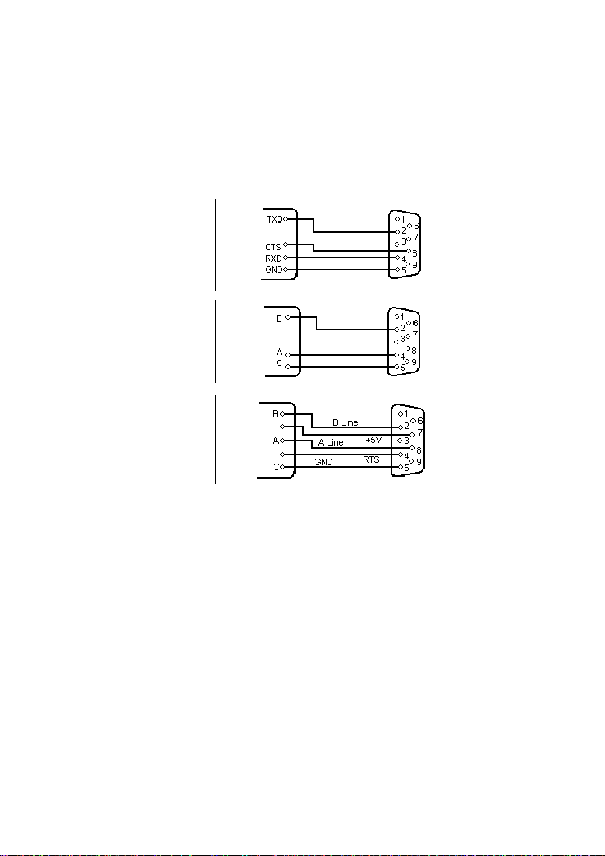
8.4. Connection Examples for
Gossen Müller & Weigert instruments
8.4.1. Connection of the IPP 144-40 GE to the DPM-MF
for the insertion of measured value into texts
For this configuration you must input and save the text as shown in section
7.4.1. of this manual.
The printer receives the measuring values via interface I / RS 232 C (also
possible via interface II). T o selected the text see section 7.4.2 in this manual.
The relevant interface is the interface for which the parameters have to be set
in the menu program. The recommended configuration is: 8 data bits, no
parity , 1 stop bit, 9600 baud. With 7 bit, no parity, the sender must be set to
2 stop bits.
DPM...MF
TxD
CTS
GND
OC 1
OC 2
3
4
2
IPP 144-40 GE
RxD
8
RTS
Interface 1
1
5
GND
5
Sign.
GND
6
7
54

8.4.2. Connection of IPP 144 - 40 G with a DAA
message display to print fault messages
Messages can be sent by all DAA type B and C versions.
(The A version DAA are not capable of outputting data but
only of displaying them since there is only one serial interface
available which is used to receive data).
The connection of the printer is made via the interface II
(RS 232 C) of the DAA. The printout is normally triggered by
a control device (e.g. a PLC) with a strobe signal (strobe T)
via the terminal strip for control inputs (parallel interface) at
the DAA.
Strobe T
DAA
TxD
CTS
GND
2
5
2
8
1
7
5
RxD
RTS
GND
Sign.
GND
IPP 144-40 G
Interface RS - 232 C:
DAA 144 - 120 B: 9 pin D - SUB 9 pin D - SUB
DAA 288 - 120 B: 25 pin D - SUB
DAA 288 - 240 B, C: 25 pin D - SUB
The required connection cable is available as an accessory .
55

8.5. Examples for Automatic text Insert mode
Example 1:
Consignment
print-out, with
time & date,
marks and
weights
Example 2:
Quality test
print-out, with
several
measured
value
Data input:
10:15:33 15/10/03 <CR>1<CR> 123 <CR> 1 <CR> 1027<CR> 997 <CR> 30 <CR>
Actual Print-out: Pre-stored texts
10:15:33 15/10/03 1 ✴✴✴✴✴✴
Product Ref: 123 2 Product Ref: ✴✴✴✴✴✴
Operator No: 1 3 Operator No: ✴✴✴✴✴✴
Gross: 1027 kg 4 Gross: ✴✴✴✴✴✴
Nett: 997 kg 5 Nett: ✴✴✴✴✴✴
Tare: 30 kg 6 Tare: ✴✴✴✴✴✴
Six blocks of data are inserted and printed in sequence.
(„✴“ = spaces reserved for
variable data)
In this example, the IPP..GE automatically adds date & time from
its own real-time clock using the „PRINT DATE / TIME-HEADLINE“
menu option. Four blocks of variable data are sent to the printer.
Data input: 115<CR> 33.7<CR> 62.8<CR> 228.7<CR>
Actual Print-out: Pre-stored texts
13.10.03 13:49:52
Metrix Electronics Ltd. 1 Metrix Electronics Ltd.
Rankine Road, Daneshill West 2 Rakine Road, Daneshill West
GB-Basingstoke RG24 8PP 3 GB-Basingstoke RG24 8PP
T est Number: 1 15 5 Test Number: ✴✴✴✴✴✴
- - - TEST RESULTS - - - 6 - - - TEST RESULTS - - Ambient T emp 33.7 ° C 7 Ambient T emp ✴✴✴✴✴✴°C
Burn-in T emp 62,8 °C 8 Burn-in-Temp ✴✴✴✴✴✴°C
Nom. Supply 230 Vac 9 Nom. Supply 230 Vac
Actual 228.7 Vac 1 0 Actual ✴✴✴✴✴✴Vac
4
Example 3:
A simple way
to print a
group of texts
56
This mode can be used to print a group of texts, triggered by a
single <CR> input, even if no variable data is required to be
inserted.
NOTE: Text No. 7 is only pre-programmed with a variable data field.
Actual Printout: Pre-stored texts
15.10.03 10:34:53
Manufactured by:: 1 Manufactured by:
2
Metrix Electronics Ltd. 3 Metrix Electronics Ltd.
Rankine Road, Daneshill West 4 Rankine Road, Daneshill West
GB-Basingstoke RG24 8PP 5 GB-Basingstoke RG24 8PP
__________________ 6 _________________
7 ✴✴✴✴✴✴
All the texts up to Text No. 6 (without variable fields) are printed. Text No. 7
(the first variable field) just prints a blank line. (If there was any variable
data sent before the <CR> this would be inserted and printed here.)

II Paper reroll mechanism IPP - AW
1. General information
The IPP-AW is a paper reroll mechanism designed for use with the Thermal
Graphics Printer IPP 144-40 G. It has been designed to match the printer in
colour and style. It is preferably installed directly underneath the printer . The
printed paper is automatically wound on a drum by a motor. A front p anel
draw allows easy paper handling.
The paper reroll mechanism is a DIN size panel mounting unit. It is supplied
with power and controlled via connector cable which comes with the unit and
which is connected to connector 12 of the IPP 144-40 G (see chapter 3.). An
LED indicates the ready status. Depending on the distance beween the two
devices at least the last 9 lines printed remain visible.
57

Design
Installation
Front Rear
1 Status indicator 2 Opening for paper feed
3 Handle 4 Connector for connection
5 Mounting screws cable IPP 144-40;
6 Protective conductor connection (pin connections: Motor
(must be connected to ground) control, +5V, open, GND)
58
The paper reroll mechanism is inserted into the DIN size
panel cutout from the front side and is clamped against the
rear of the switchboard using the mounting screws. The
switchboard thickness must not exceed 12 mm.
Make sure that the unit is properly mounted
before connection and power on.

2. Technical data
Winding
Ambient
conditions
Standards
Miscellaneous
Connection
Motor with friction clutch, electronic lag 3 sec
Paper width: max. 80 mm
Paper length: max. 15 m
Store temperature range: -20 °C to +80 °C
Operating temperature range: 0 °C to +70 °C
Climate: relative humidity
< 80 % up to 31 °C
Protection type housing: IP 50 acc. to
EN 60528/VDE 0470
Mech.strength: T o IEC 1010
Safety: EN 61010-1:2001
CA TIII >150V≤300V
Pollution degree 2
EMC
Susceptibility: DIN EN 610004-1
to EN 610004-4
Emission: DIN EN 50081-2
Class B
Dimensions (WxHxD): 144 x 72 x 159 mm
Connector: MASCON female
multi point connector,
4 pin keyed
Connector cable: AWG 26,
approx. 100mm
Power supply: by IPP (5 V DC)
Maintenance
friction
clutch
CE
The torque of the friction clutch has been factory adjusted
and should not require adjustment.
The winding force of the motor can be adjusted by slightly
rotating the screw accessible through the left hand side
hole in the body:
➨➨
➨ less = turn left
➨➨
➨➨
➨ more = turn right
➨➨
59

3. Operation
Removing
the paper
Inserting
the paper
60
➨➨
➨ Use the handle (4) to pull out the front panel (1).
➨➨
➨ Remove the holder (3) with the paper from roll body,
rotate the notch of the holder as show in the diagram.
➨ Remove the paper drum from the holder.
➨ Wind the paper once around the drum body (2) in the
direction indicated by the arrow.
➨ Plug in the holder (3) in such a way that the pins fit
into the notches of the body .
➨ Close the front panel.
➨ Briefly press the „LINE FEED“ key at the
IPP 144 - 40 G until the paper has been straightened
out.

III Accessories
◆◆
◆ Paper reroll mechanism IPP - A W
◆◆
(incl. connection cable).
◆ Protection cover for use of IPP 144-40 G with IPP-A W,
Protection class: IP 64.
Dimensions: 155 x 155 [mm].
Material: Plexiglas and
Santoprene 101-80 rubber
◆ Connection cable for serial data transmission
to the following devices:
IBM-PC XT and A T or compatibles
Siemens PG 685 (V 24)
Siemens PG 675 / 685 (printer interface)
Siemens GP270 /TP270/MP370 TOUCH(RS232C)
(printer interface)
Message displays:
DAA 144-120B / 288-120B / 288-240B, C
others on request.
Connection cable for USB-interface:
USB-A connector - USB-B connector
◆ Windows programming software for IPP 144-40 GE version (CD-R)
61

GOSSEN Müller & Weigert
Kleinreuther Weg 88
D-90408 Nürnberg
T el.: 091 1/3502-0 Fax: 091 1/3502-307
E-mail: info@g-mw.de http://www .g-mw .de
We reserve the right to make alterations! 09.05 Order no.: 27866 88137
 Loading...