

GMV 3010 Installation, Use And Maintenance Manual
GMV SPA
FLUID DYNAMICS EQUIPMENTS AND
COMPONENTS FOR LIFTS
UNI EN ISO 9001
Certified Company
1.01
ENG
English
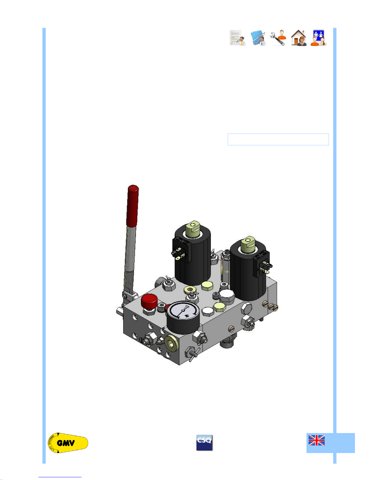
3010 ¾” VALVE
SELL
TECH
WORK
CUST
USER
3010 ¾” VALVE MANUAL
INSTALLATION, USE AND MAINTENANCE
1 0991 497 EN
AVAILABLE WITH TANK TYPE
HL, HL DRY, HL 50 DRY, HLV, HLV 40 e GL
1 0991 497 EN - 24.03.2017
1.01
ENG
3010 ¾” VALVE MANUAL
INSTALLATION, USE AND MAINTENANCE
2 / 16
GMV Spa declines all responsibility in case you do not follow the instructions in this document.
In particular, disregarding these instructions,may cause safety problems in the installation and for the users.
INDEX
0 GENERAL SECTION 3
0.1 INTRODUCTION 3
0.1.1 DEFINITIONS 3
0.1.2 RULES REFERENCE 4
0.2 INSTALLATION RELATED DOCUMENTS 4
0.3 SAFETY PRECAUTION DURING INSTALLATION 4
0.4 TOOLING 4
0.5 GENERAL ORDERS 4
0.6 LIABILITY AND WARRANTY 5
0.7 WARNINGS BEFORE THE INSTALLATION 5
0.8 CLEANING AND POLLUTION PROTECTION 5
1 FEATURES AND REQUIREMENTS 6
1.1 THE 3010 ¾” VALVE 6
1.2 THE FLUID 6
2 INSTALLATION OPERATIONS 6
2.1 HYDRAULIC CONNECTIONS 6
2.2 3010 ¾” VALVE DIMENSIONS 7
2.3 HYDRAULIC CIRCUIT 7
2.4 DECELERATION DISTANCES AND SIGNALS 8
2.5 ELECTRICAL CONNECTIONS 8
2.6 CONNECTION BOX 8
2.6.1 POWER UNITS WITH IMMERSED MOTOR 8
2.6.2 POWER UNITS WITH DRY MOTOR 8
2.7 HYDRAULIC CONNECTIONS 9
2.7.1 CONNECTION WITH HOSE 9
2.7.2 RIGID TUBE CONNECTION 9
3 ADJUSTMENTS AND TESTS 9
3.1 ADJUSTMENT OF THE MINIMUM PRESSURE UPWARD – N° 11 9
3.2 ADJUSTMENT OF THE OVERPRESSURE – N° 1 9
3.3 ADJUSTMENT OF THE UPWARD ACCELERATION – N° 4 10
3.4 ADJUSTMENT OF SLOW LEVELLING SPEED – N° 2 10
3.5 ADJUSTMENT OF THE UPWARD HIGH SPEED – N° 8 10
3.6 ADJUSTMENT OF THE DOWNWARD ACCELERATION – N° 7 10
3.7 ADJUSTMENT OF THE DOWNWARD HIGH SPEED – N° 9 10
3.8 ADJUSTMENT OF THE UPWARD AND DOWNWARD DECELERATION – N° 3 10
3.9 PIPE RUPTURE VALVE (VC) TEST (IN THE VALVE BLOCK) – N° 5 11
3.10 ADJUSTMENT OF THE MINIMUM RAM PRESSURE, VSMA – N° 6 11
3.11 MANUAL LOWERING OPERATION (EMERGENCY ONLY) – BUTTON (MM) 11
3.12 ADJUSTMENT OF THE MAXIMUM PRESSURE - HAND PUMP 11
4 MAINTENANCE AND FAULT ANALYSIS 12
4.1 PROGRAMMED MAINTENANCE 12
4.2 PERIODICAL MAINTENANCE AND CHECKS TABLE 12
4.3 MAINTENANCE OPERATIONS 12
4.4 FAULT ANALYSIS 14
ENG
All rights reserved.
Any kind of exploitation in any form and by any means is forbidden without a written permission of GMV Spa.
GMV Spa, within technical or manufacturing progress, reserves the right to modify parts or this manual without notice.
Drawings, descriptions and data included in this manual are indicatives.
For all the data not included in this manual refer to the documents of any single part.
To guarantee the products security, do not use spare parts not genuine or not approved by GMV Spa.
GMV Spa will not assume any responsibility if the instructions included in this manual are not observed.
DT 24/03/2017
PR 24/03/2017
GF 24/03/2017
WARNING – IMPORTANT

ENG
1.01
1 0991 497 EN - 24.03.2017
3 / 16
3010 ¾” VALVE MANUAL
INSTALLATION, USE AND MAINTENANCE
Support and informations:
FLUID DYNAMICS EQUIPMENTS AND
COMPONENTS FOR LIFTS
UNI EN ISO 9001
Certified Company
GMV SPA
Via Don Gnocchi, 10 - 20016 PERO – Milano (Italy)
TEL. +39 02 33930.1 - FAX +39 02 3390379
http://www.gmv.it - e-mail: info@gmv.it
Visit www.gmv.it to check for updates of this document and other product information from
GMV.
Main acronyms and abbreviations
1
Pressure safety valve adjustment (p.max)
2
Levelling / slow speed adjustment (up/down)
3
Deceleration adjustment (up/down)
4
Upward start adjustment
5
Screw for rupture valve test ( EN 81.20)
6
Minimum ram pressure adjustment
7
Downward start adjustment
8
High speed adjustment
9
Down speed compensator (empty/full load)
10
Hand pump max. pressure adjustment
11
Minimum upward pressure adjustment
RUB
Shut-off valve for pressure gauge exclusion
MAN
Pressure gauge
MM
Manual lowering button
PAM
Hand pump
V
Hand pump air purge screw
VP
Pilot valve
CHK
Check valve
VMD
Downward solenoid valve
VML
Jump speed solenoid valve (upward/downward)
PRS
Gauge fitting
S4
Fixed filer (don’t remove)
ISP
Inspection gauge fitting (EN 81.20)
S
Ball valve
PRF
Blocking screw (don’t remove)
0 GENERAL SECTION
0.1 INTRODUCTION
0.1.1 DEFINITIONS
NOTES
Indicates information which contents must be seriously taken in consideration.
WARNING
Indicates that the described operation may cause, damages to the system or physical damages if
performed without complying with the safety standards.
1 0991 497 EN - 24.03.2017
1.01
ENG
3010 ¾” VALVE MANUAL
INSTALLATION, USE AND MAINTENANCE
4 / 16
0.1.2 RULES REFERENCE
For all definitions not included in this manual please refer to rules and local laws in force, following, particularly:
- EN 81-2: Safety rules for the construction and installation of lifts,
- UNI–EN-ISO-14121: Safety of machinery - Principles for risk assessment,
- ISO 3864: Safety colours and safety signs
- MD 2006/42: Machine directive.
0.2 INSTALLATION RELATED DOCUMENTS
The documents to use for the installation are those required by the EN81-20:2014 and by the rules in force,
particularly the following:
- THIS INSTALLATION MANUAL
- WIRING AND HYDRAULIC DIAGRAMS (EN81-20 7.3.2.A.6 AND 7).
All the documentation for a correct and safe installation must be stored by the installation responsible.
Please remember that this documentation is considered part of the plant and must be complete, well stored and
unabridged in every part.
In order to maintain the readability, the documentation shouldn’t be damaged and shouldn’t have missing parts.
Moreover, do not tear or deteriorate sheets during consulting.
0.3 SAFETY PRECAUTION DURING INSTALLATION
WARNING
Before starting all kind of installation operation:
ALWAYS verify that all the safety devices, mechanical or electrical, are active and working properly.
0.4 TOOLING
Use standard building-yard tooling for the installation.
0.5 GENERAL ORDERS
The valves shall be maintained in good working order in accordance with the Standards.
To this effect, regular maintenance of the installation shall be carried out, to ensure, in particular, the safety of
the installation.
The safety of an installation shall take into account the ability to be maintained without causing injury or damage
to health.
Regular maintenance of the installation shall be carried out to ensure the reliability of the installation.
The access and the associated environment shall be maintained in good working order.
The competence of the maintenance person within the maintenance organization shall be continuously updated.
NOTE
We inform the owner of the installation that the qualification of the maintenance organization
ENG
1.01
1 0991 497 EN - 24.03.2017
5 / 16
3010 ¾” VALVE MANUAL
INSTALLATION, USE AND MAINTENANCE
needs to be in conformity with the rules applicable in the country in which the installation operates;
if no rules exist, the qualification can be ensured by a certified EN ISO 9001 quality system
supplemented if necessary to take into account the specific features of the installation.secondo le
EN ISO 9001.
0.6 LIABILITY AND WARRANTY
These instructions are intended for people with experience in installation, adjustment and maintenance of
hydraulic lifts.
GMV disclaims any liability for damage caused by improper or different use from what described in these
instructions or inexperience or carelessness of those responsible to assemble, adjust or repair hydraulic
components.
GMV's warranty is voided if you install any components or parts not original, if you make unauthorized changes
or modifications or made by unauthorized or unqualified personnel.
Unless otherwise indicated, the following situations are forbidden for safety reasons:
- Any product modification;
The installation of the product for purposes other than those described;
Damage to the joints;
Carrying out maintenance or inspections improper or inadequate;
The use of improper accessories and not original spare parts or materials from GMV.
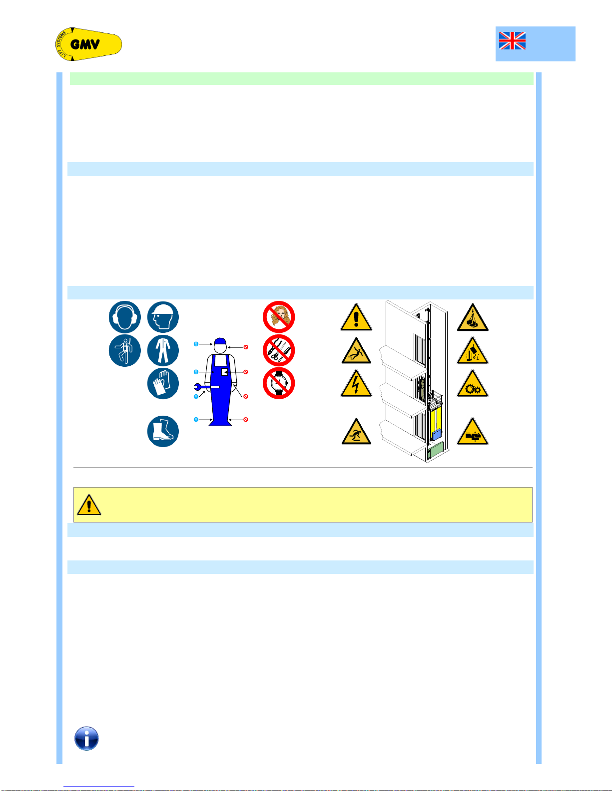
0.7 WARNINGS BEFORE THE INSTALLATION
In these instructions the major points concerning the safety and prevention will be marked with the following
symbols:
General warning.
Warning high risk of danger. Risk of injury (e.g., crushing, sharp edges, protrusions, etc..).
Warning risk of electrical damage (exposed parts).
Beyond the instruction manual, it should take into account national standards, laws, regulations and other rules
on accident prevention and environmental protection, and special operating conditions, such as the use of the
lift, tools and equipment working.
The installation and repair technicians are primarily responsible for their own safety.
This "Manual" applies to the entire life of the facility, during normal operation, testing and maintenance to be an
integral part of the system, so it should be kept in a safe place by the installer.
The installation, commissioning and maintenance of the system may only be performed by trained personnel.
Before starting the installation work:
Use safety devices to protect personnel and prevent falls;
Cover (safely) openings in walls and floor;
Use the tools and means preventing accidental falls;
The gaps should be closed, use appropriate warning signs.
Work on electrical equipment must be performed by an electrician or other qualified personnel.
0.8 CLEANING AND POLLUTION PROTECTION
Impurities and dirty inside the equipment may cause malfunction of the hydraulic system and premature wear.
All disassembled items for inspection or repair, as well as pipes and accessories should be thoroughly cleaned
before re-assembled.
 Loading...