


2.Montaj Açıklamaları
3.Bağlantı Arayüzü
4.İşletim Modu
GMTCNT
GOP70-070WP / GOP70-101WP
Human Machine Interface Operatör Panel
Kullanım Talimatları
Doğrudan güneş ışığının alındığı
Hızlı sıcaklık değişiminin veya yüksek nemin
olduğu
Patlama tehlikesi olan
Yanıcı gazların bulunduğu
Buharlı ve tozlu
Sarsıntılı veya titreşimli
ortamlarda kullanmayınız.
Elektriksel, elektrostatik veya
elektromanyetik gürültünün
bulunduğu
Güç kayanağına yakın
ortamlarda ekranlama yapınız.
1.1 Çevre Şartları
Cihazın montajı yapılırken, AC güç kablolarının, PLC çıkış modüllerinin, kontaktörlerin, rölelerin ve
buna benzer diğer elektriksel birimlerin cihazın arka bölgesinden uzakta olmasına özen
gösterilmelidir.
2.3 Güç Bağlantıları
Güç kaynağı kabloları için lütfen güvenlik şartnamelerine uygun olan dielektrik değere ve akım
değerlerine sahip kablolar seçiniz. Kablo bağlantı uçları aşağıdaki gibidir.
3.1 Güç beslemesi ve Seri bağlantı portu
Güç beslemesi ve seri port aşağıda gösterildiği gibi aynı soketi kullanır
1.2 Güç Gereksinimleri
Giriş Gerilimi: 12~28VDC;
Ürün ve konverterler veya kesintisiz güç kaynağı arasında yeterli mesafe olmalıdır. Bu
tarz cihazların giriş çıkışlarında ekranlı kablo kullanıldığına ve bunların da topraklama
hattına bağlı olduğuna emin olunuz
DC kaynaklar ana AC güç kaynağından izole edilmelidir. .
Sürekli yük veya kontrol cihazının giriş devresi ile ortak güç kullanmayınız.
İçerdeki sigorta aşırı gerilim durumunda cihazın zarar görmesini
önleyecektir. Ancak, içerdeki elektronik parçaların zarar görmeyeceği
garanti edilmemektedir.
durumunda cihazın zarar görmesini önleyecektir. Ancak, içerdeki elektronik parçaların zarar
görmeyeceği garanti edilmemektedir
2.1 Motaj açıklamaları
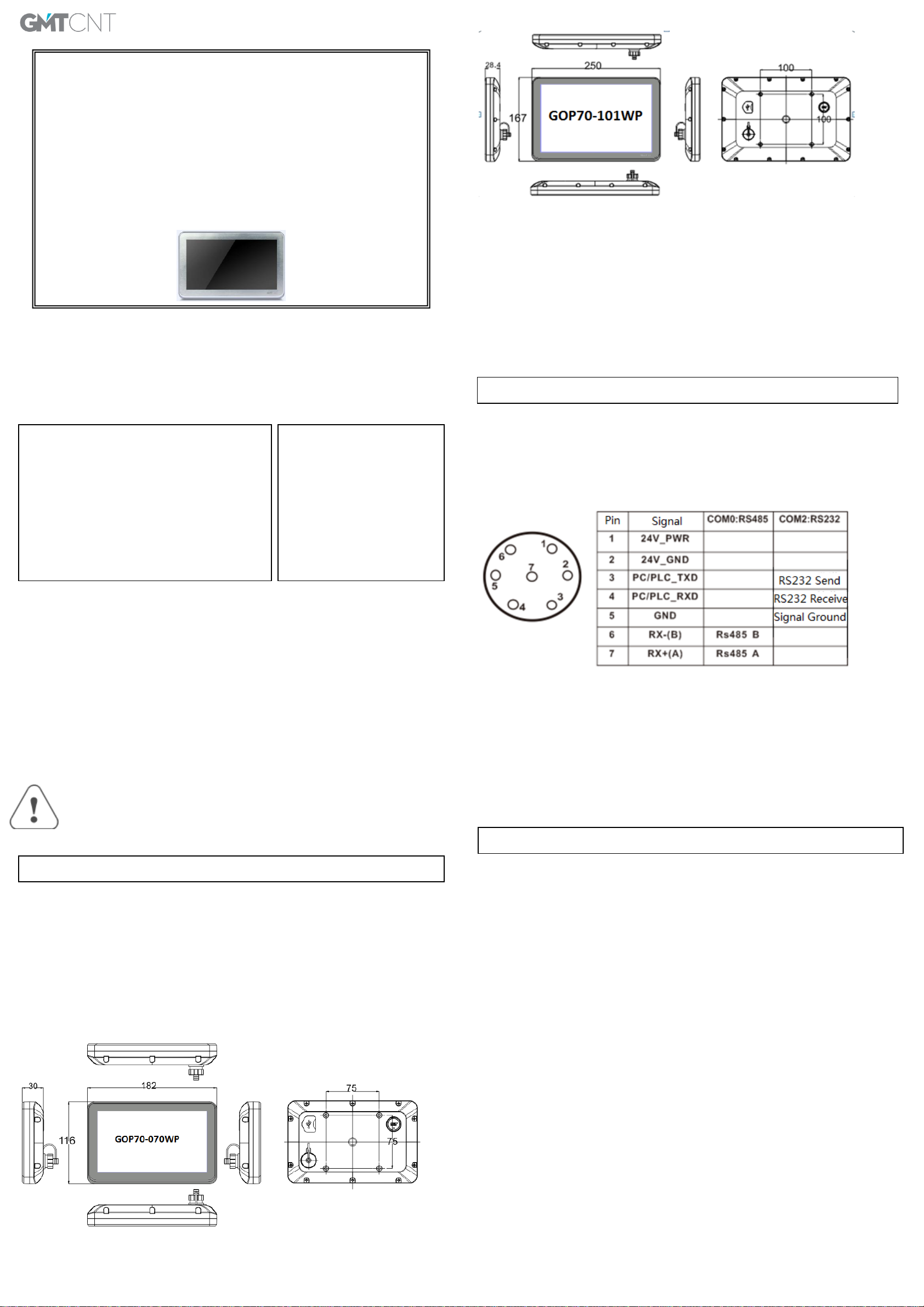
VESA standartlarına uygun 4 montaj deliği 070WP için 75mm*75mm, 101WP için 100mm*100mm
dir.
Not:İki adet haberleşme portu vardır. Com0 RS485 ve Com2 RS232 şeklindedir. Com2 portu aynı
zamanda PC den program yükleme amacı ile de kullanılır.
3.2 USB HOST
BU port genle olarak açılış logosu, kullanıcı konfigürayonu upload ve download, reçete ve kayıtlı data
yüklemelri için kullanılır.
4.1 İşletim mode seçim penceresime giriş
Cihaza enerji verilmeden önce ekrana basılı tutulup enerji verildiğinde seçim penceresi
2.2 Ebatlar (mm)
görünecektir.
4.2 İşletim mode seçim penceresi modları
System Setup: Bu menüden açılış penceresi numarası, screen saver zamanı , buzzer
actik pasif ,parlalklık gibi ayarlamalar yapabilirsniz.
Firmware Update:Firmware güncelleme için kullanılan bu menu bilinçli kullanılmalıdır.
Touch Calibration:Dokunmatik ekran kalibrasyonu menüsüdr.
Stop timer: 20s lik zamanlayıcıyı durdurmak için kullanılar. Zamanlayıcı herhnagi birr işlme
yapılamdığ zman bekleme süresidir
GMT Endüstriyel Elektronik San. ve Tic. Ltd. Şti.
Kavacık Mah. Yurtsever Sk. No:2 Beykoz / İstanbul -Turkey
Tel : +90 216 668 0006 Pbx. Fax : +90 216 668 0008
url : www.gmtcontrol.com
3.External Interface
4.Operation Mode
F7
F10
GMTCNT
GOP70-070WP / GOP70-101WP
Human Machine Interface
Installation Instructions
2.Installation Description
Please take shielding
measures in the following
places:
Places that exist electrostatic
or other kinds of noise
Places of strong
electromagnetic
Places that may be exposed to
Please do not use in the following places:
Places direct in sunlight
Surroundingtemperature and humidity beyond the
specifications
Places of temperature changes sharply and easily
cause condensation
Places that exist corrosive gas and combustible gas
1.1 Environmental Requirement
Please make sure that AC power,PLC output modules,starters,relays and other types of electrical
interface device are far away from the back of this product.
2.3 Power Connection
Before connecting the power, please make sure all local and national electrical standards are met.
For power cables, please select cables with these specifications: overall diameter 6.--8.3mm, 7 cable
cores,the internal cable cores should be 22AWG or above.The power cable is welded to WF-16
connector.The definition of the WF-16 connector is as shown in chapter 3.1.In the picture,24V_PWR is
connected to DC24V,and 24V_GND is connected to 0V.
3.1 Power Supply&Serial Port
The power supply and serial port use the same connector,as shown in following picture.
1.2 Power Requirement
Input voltage: 18~28VDC;
Particularly note that there must be enough distance between this product and converters or
switch mode power supply. Make sure that the input and output cables of that kind equipment
are shield cable and the shielding network is connected with the ground.
Make sure that the DC power and AC power is isolated.
Do not use common power with perceptual load or input circuit of the controller.
An Internal fuse will prevent damage for over voltage condition, however it isn’t
guaranteed the internal electronic components are not damaged.
Chassis ground must be used.
Note:There are two communication ports.One is COM0,it supports RS485.The other one is COM2
which is used for RS232 communication and downloading project.
3.2 USB HOST
This interface is mainly used for importing initial LOGO,user’s configuration uploading/
downloading,recipe data import/export and historical data export.
2.1 Installation Instructions
It uses bracket installation which is compatible with VESA standard.The 4 installation holes for
070WP is 75mm*75mm,and for 101WP is 100mm*100mm,the installation holes distance is as shown in
chapter 2.2.
2.2 Dimensional Drawing (mm)
4.1 Instructions for entering Operation Mode selection window
Press and hold the touch panel before power on HMI,then power on HMI.Release your help after
HMI enter operation mode selection window,then select the operation mode.If no any operation in 20s
after entering operation mode selection window,HMI will enter application mode automatically.
4.2 Descriptions of functions in Operation Mode selection window
After entering operation mode selection window,it will popup a menu.Follows are the descriptions of
the functions in the menu:
System Setup:Press this button to enter system setup window.This window is used to set initial
window,screen saver time,buzzer and brightness adjustment.After setting,press Restart button to restart
HMI.
Firmware Update:Press this button to enter firmware update window.This window is used to update
firmware.Normally this mode is not advised to use without guiding by manufacturer.
Touch Calibration:Press this button to enter touch calibration window.It will restart HMI automatically
after calibration successful.There is a timer in this button,it will enter application window if there is no
operation within 20s.
Stop timer: Press this button to stop the 20s timer.
 Loading...