

GMT G781 Datasheet
Global Mixed-mode Technology Inc.
G781
±1°C Remote and Local Temperature Sensor with
SMBus Serial Interface
Features
Two Channels: Measures Both Remote and
Local Temperatures
No Calibration Required
SMBus 2-Wire Serial Interface
Programmable Under/Overtemperature Alarms
Supports SMBus Alert Response
Accuracy:
±1°C (+60°C to +100°C, remote)
±3°C (+60°C to + 100°C, local)
320µA (typ) Average Supply Current During
Conversion
+3V to +5.5V Supply Range
Small 8-Lead SO Package
Applications
Desktop and Notebook Central Office
Computers Telecom Equipment
Smart Battery Packs Test and Measurement
LAN Servers Multi-Chip Modules
Industrial Controllers
General Description
The G781 is a precise digital thermometer that reports
the temperature of both a remote sensor and its own
package. The remote sensor is a diode-connected
transistor typically a low-cost, easily mounted 2N3904
NPN type that replace conventional thermistors or
thermocouples. Remote accuracy is ±1°C with no calibration needed. The remote channel can also measure the die temperature of other ICs, such as microprocessors, that contain an on-chip, diode-connected
transistor.
The 2-wire serial interface accepts standard System
Management Bus (SMBus) Write Byte, Read Byte,
Send Byte, and Receive Byte commands to program
the alarm thresholds and to read temperature data.
The data format is 11bits plus sign, with each bit corresponding to 0.125°C, in two’s-complement format.
Measurements can be done automatically and
autonomously, with the conversion rate programmed
by the user or programmed to operate in a single-shot
mode. The adjustable rate allows the user to control
the supply current drain.
The G781 is available in a small, 8-pin SOP surface-mount package.
Ordering Information
PART* TEMP. RANGE PIN-PACKAGE
G781 -20°C to +120°C 8-SOP
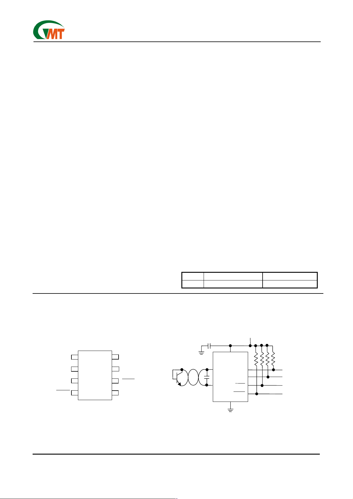
Pin Configuration Typical Operating Circuit
3V TO 5.5V
3V TO 5.5V
0.1µF
0.1µF
G781
G781
VCC
DXP
DXP
DXN
DXN
VCC
SMBCLK
SMBCLK
SMBDATA
SMBDATA
ALERT
ALERT
THERM
THERM
GND
GND
VCC
VCC
DXP
DXP
DXN
DXN
THERM
THERM
1
1
2
2
3
3
4
4
8 Pin SOP
8 Pin SOP
8
8
7
7
6
6
5
5
SMBCLK
SMBCLK
SMBDATA
SMBDATA
ALERT
ALERT
GND
GND
2N3904
2N3904
2200pF
2200pF
10kΩEACH
10kΩEACH
CLOCK
CLOCK
DATA
DATA
INTERRUPT TO µC
INTERRUPT TO µC
Ver: 1.0
Oct 02, 2002
1
TEL: 886-3-5788833
http://www.gmt.com.tw
Global Mixed-mode Technology Inc.
Absolute Maximum Ratings
VCC to GND………….….……..………….-0.3V to +6V
DXP to GND……….……………..…-0.3V to VCC + 0.3V
DXN to GND……………..……………..-0.3V to +0.8V
SMBCLK, SMBDATA, ALERT to GND..…-0.3V to +6V
SMBDATA,
DXN Current……………………..………………….±1mA
ESD Protection (SMBCLK, SMBDATA,
Stresses beyond those listed under “Absolute Maximum Ratings” may cause permanent damage to the device. These are
stress ratings only, and functional operation of the device at these or any other conditions beyond those indicated in the operational sections of the specifications is not implied. Exposure to absolute maximum rating conditions for extended periods may
affect device reliability.
ALERT Current………….-1mA to +50mA
ALERT , human
body model).……………………………………….2000V
ESD Protection (other pins, human body model)..2000V
Continuous Power Dissipation (T
(derate 8.30mW/°C above +70°C)…………......667mW
Operating Temperature Range………-20°C to +120°C
Junction Temperature………………….………..+150°C
Storage temperature Range………….-65°C to +165°C
Lead Temperature (soldering, 10sec)……..……...+300°C
G781
= +70°C) ..SOP
A
Electrical Characteristics
(VCC = + 3.3V, TA = 0°C to +85°C, unless otherwise noted.)
PARAMETER CONDITIONS MIN TYP MAX UNITS
TR = +60°C to +100°C, VCC = 3.0V to 3.6V -1 +1 Temperature Error, Remote Di-
ode (Note 1)
Temperature Error, Local Diode
Supply-Voltage Range 3.0 5.5 V
Undervoltage Lockout Threshold VCC input, disables A/D conversion, rising edge 2.8 V
Undervoltage Lockout Hysteresis 50 mV
Power-On Reset Threshold VCC, falling edge 1.7 V
POR Threshold Hysteresis 50 mV
Standby Supply Current Logic inputs forced to VCC or GND
Current
Conversion Time From stop bit to conversion complete (both channels) 125 ms
Conversion Rate Timing Conversion-Rate Control Byte=04h, 1Hz 1 sec
Remote-Diode Source Current
= 0°C to +125°C (Note 2) -3 +3
T
R
TA = +60°C to +100°C -3 +3
T
= 0°C to +85°C (Note 2) -5 +5
A
SMBus static 3
Auto-convert mode. Logic inputs
forced to VCC or GND
DXP forced to 1.5V
Hardware or software
standby, SMBCLK at 10kHz
0.5 conv/sec 35 Average Operating Supply
8.0 conv/sec 320
High level 176
Low level 11
4
°C
°C
µA
µA
µA
Ver: 1.0
Oct 02, 2002
2
TEL: 886-3-5788833
http://www.gmt.com.tw
Global Mixed-mode Technology Inc.
Electrical Characteristics
(VCC = + 3.3V, T
= 0 to +85°C, unless otherwise noted.)
A
(continued)
G781
PARAMETER CONDITIONS MIN TYP MAX UNITS
SMBus Interface
, SMBCLK, SMBDATA; Vcc = 3V to 5.5V
Logic Input High Voltage
Logic Input Low Voltage
Logic Output Low Sink Current
ALERT
Logic Input Current Logic inputs forced to VCC or GND -2 2 µA
SMBus Input Capacitance SMBCLK, SMBDATA 5 pF
SMBus Clock Frequency 100 kHz
SMBus Timeout SMBCLK low time for interface reset 30 ms
SMBCLK Clock Low Time t
SMBCLK Clock High Time t
SMBus Start-Condition Setup Time 4.7 µs
SMBus Repeated Start-Condition Setup Time t
SMBus Start-Condition Hold Time t
SMBus Stop-Condition Setup Time t
SMBus Data Valid to SMBCLK Rising-Edge
Time
SMBus Data-Hold Time t
SMBCLK Falling Edge to SMBus Data-Valid
Time
Output High Leakage Current
STBY
, SMBCLK, SMBDATA; Vcc = 3V to 5.5V
STBY
ALERT
ALERT
t
SMBCLK
Master clocking in data 1 µs
, SMBDATA forced to 0.4V
forced to 5.5V
, 10% to 10% points 4.7 µs
LOW
, 90% to 90% points 4 µs
HIGH
90% to 90% points 500 ns
SU : STA ,
10% of SMBDATA to 90% of SMBCLK 4 µs
HD: STA ,
90% of SMBCLK to 10% of SMBDATA 4 µs
SD: STO ,
10% or 90% of SMBDATA to 10% of
SU: DAT ,
300 ns
HD : DAT
2.4 V
0.8 V
6 mA
1 µA
800 ns
Note 1:
A remote diode is any diode-connected transistor from Table1. T
is the junction temperature of the remote
R
of the remote diode. See Remote Diode Selection for remote diode forward voltage requirements.
Note 2:
Guaranteed by design but not 100% tested.
Pin Description
PIN NAME FUNCTION
1 VCC Supply Voltage Input, 3V to 5.5V. Bypass to GND with a 0.1µF capacitor.
Combined Current Source and A/D Positive Input for remote-diode channel. Do not leave DXP float-
2 DXP
3 DXN Combined Current Sink and A/D Negative Input.
4
5 GND Ground
6
7 SMBDATA SMBus Serial-Data Input / Output, open drain
8 SMBCLK SMBus Serial-Clock Input
THERM
ALERT
ing; tie DXP to DXN if no remote diode is used. Place a 2200pF capacitor between DXP and DXN for
noise filtering.
Open-drain output. Requires pull-up to VCC.
SMBus Alert (interrupt) Output, open drain
Ver: 1.0
Oct 02, 2002
3
TEL: 886-3-5788833
http://www.gmt.com.tw
Global Mixed-mode Technology Inc.
Detailed Description
The G781 is a temperature sensor designed to work in
conjunction with an external microcontroller (µC) or
other intelligence in thermostatic, process-control, or
monitoring applications. The µC is typically a powermanagement or keyboard controller, generating
SMBus serial commands by “bit-banging” generalpurpose input-output (GPIO) pins or via a dedicated
SMBus interface block.
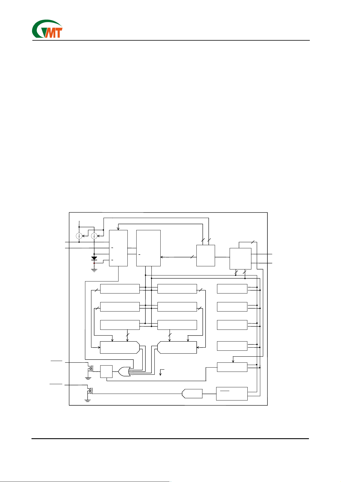
Essentially an serial analog-to digital converter (ADC)
with a sophisticated front end, the G781 contains a
switched current source, a multiplexer, an ADC, an
SMBus interface, and associated control logic (Figure
1). Temperature data from the ADC is loaded into two
data registers, where it is automatically compared with
data previously stored in several over/under- temperature alarm registers.
G781
ADC and Multiplexer
The ADC is an averaging type that integrates over a
60ms period (each channel, typical), with excellent
noise rejection.
The multiplexer automatically steers bias currents
through the remote and local diodes, measures their
forward voltages, and computes their temperatures.
Both channels are automatically converted once the
conversion process has started, either in free-running
or single-shot mode. If one of the two channels is not
used, the device still performs both measurements,
and the user can simply ignore the results of the unused channel. If the remote diode channel is unused,
tie DXP to DXN rather than leaving the pins open.
The worst-case DXP-DXN differential input voltage
range is 0.25V to 0.95V.
Excess resistance in series with the remote diode
causes about +0.6°C error per ohm. Likewise, 240µV
of offset voltage forced on DXP-DXN causes about
1°C error.
DXP
DXP
DXN
DXN
ALERT
ALERT
V
V
CC
CC
MUX
MUX
2
REMOTE TEMPERATURE
REMOTE TEMPERATURE
11
11
HIGH-TEMPETATURE
HIGH-TEMPETATURE
11
11
THRESHOLD (REMOTE
THRESHOLD (REMOTE
LOW-TEMPETATURE
LOW-TEMPETATURE
THRESHOLD (REMOTE
THRESHOLD (REMOTE
DIGITAL COMPARATOR
DIGITAL COMPARATOR
Q
Q
R
R
+
+
REMOTE
REMOTE
LOCAL
LOCAL
+
+
DIODE
DIODE
FAULT
FAULT
DATA REGISTER
DATA REGISTER
(REMOTE)
(REMOTE)
S
S
2
ADC
ADC
+
+
CONTROL
CONTROL
LOGIC
LOGIC
LOCAL EMPERATURE
LOCAL EMPERATURE
DATA REGISTER
DATA REGISTER
HIGH-TEMPETATURE
)
)
HIGH
HIGH
)
)
LOW
LOW
11
11
HIGH-TEMPETATURE
THRESHOLD (LOCALT
THRESHOLD (LOCALT
LOW-TEMPETATURE
LOW-TEMPETATURE
THRESHOLD (LOCAL T
THRESHOLD (LOCAL T
8
8
DIGITAL COMPARATOR
DIGITAL COMPARATOR
(LOCAL)
(LOCAL)
SELECTED VIA
SELECTED VIA
SLAVE ADD = 0001 100
SLAVE ADD = 0001 100
HIGH
HIGH
LOW
LOW
8
8
8
8
)
)
)
)
SMBUS
SMBUS
READ
READ
COMMAND BYTE
COMMAND BYTE
(INDEX) REGISTER
(INDEX) REGISTER
STATUS BYTE
STATUS BYTE
REGISTER
REGISTER
CONFIGURATION
CONFIGURATION
BYTE REGISTER
BYTE REGISTER
CONVERSION RATE
CONVERSION RATE
REGISTER
REGISTER
ALERT RESPONSE
ALERT RESPONSE
ADDRESS REGISTER
ADDRESS REGISTER
7
7
SMBDATA
SMBDATA
SMBCLK
WRITE
WRITE
8
8
8
8
SMBCLK
THERM
THERM
Ver: 1.0
Oct 02, 2002
THERM LIMIT AND
COMPARATOR
COMPARATOR
THERM LIMIT AND
HYSTERESIS REGISTER
HYSTERESIS REGISTER
Figure 1. Functional Diagram
TEL: 886-3-5788833
http://www.gmt.com.tw
4
Global Mixed-mode Technology Inc.
A/D Conversion Sequence
If a Start command is written (or generated automatically in the free-running auto-convert mode), both
channels are converted, and the results of both measurements are available after the end of conversion. A
BUSY status bit in the status byte shows that the device is actually performing a new conversion; however,
even if the ADC is busy, the results of the previous
conversion are always available.
Remote Diode Selection
Temperature accuracy depends on having a goodquality, diode-connected small-signal transistor. The
G781 can also directly measure the die temperature of
CPUs and other integrated circuits having on-board
temperature-sensing diodes.
The transistor must be a small-signal type with a relatively high forward voltage; otherwise, the A/D input
voltage range can be violated. The forward voltage
must be greater than 0.25V at 10µA; check to ensure
this is true at the highest expected temperature. The
forward voltage must be less than 0.95V at 300µA;
check to ensure this is true at the lowest expected
temperature. Large power transistors don’t work at all.
Also, ensure that the base resistance is less than
100Ω. Tight specifications for forward-current gain
(+50 to +150, for example) indicate that the manufacturer has good process controls and that the devices
have consistent V
Thermal Mass and Self-Heating
Thermal mass can seriously degrade the G781’s effective accuracy. The thermal time constant of the
SOP- package is about 140 in still air. For the G781
junction temperature to settle to within +1°C after a
sudden +100°C change requires about five time constants or 12 minutes. The use of smaller packages for
remote sensors, such as SOT23s, improves the situation. Take care to account for thermal gradients between the heat source and the sensor, and ensure that
stray air currents across the sensor package do not
interfere with measurement accuracy. Self-heating
does not significantly affect measurement accuracy.
Remote-sensor self-heating due to the diode current
source is negligible. For the local diode, the worst-case
error occurs when auto-converting at the fastest rate
characteristics.
be
G781
and simultaneously sinking maximum current at the
ALERT
ALERT
VCC x 320µA plus 0.4V x 1mA. Package theta J-A is
about 120°C /W, so with VCC = 3.3V and no copper PC
board heat-sinking, the resulting temperature rise is:
dT = 1.45mW x 120°C /W = 0.17°C
Even with these contrived circumstances, it is difficult
to introduce significant self-heating errors.
Table 1. Remote-Sensor Transistor Manufacturers
Philips PMBS3904
Motorola(USA) MMBT3904
National Semiconductor (USA) MMBT3904
Note:Transistors must be diode-connected (base
shorted to collector).
ADC Noise Filtering
The ADC is an integrating type with inherently good
noise rejection. Micropower operation places constraints on high-frequency noise rejection; therefore,
careful PC board layout and proper external noise filtering are required for high-accuracy remote measurements in electrically noisy environments.
High-frequency EMI is best filtered at DXP and DXN
with an external 2200pF capacitor. This value can be
increased to about 3300pF(max), including cable capacitance. Higher capacitance than 3300pF introduces
errors due to the rise time of the switched current
source.
Nearly all noise sources tested cause the ADC measurements to be higher than the actual temperature,
typically by +1°C to 10°C, depending on the frequency
and amplitude.
PC Board Layout
Place the G781 as close as practical to the remote
diode. In a noisy environment, such as a computer
motherboard, this distance can be 4 in. to 8 in. (typical)
or more as long as the worst noise sources (such as
CRTs, clock generators, memory buses, and ISA/PCI
buses) are avoided.
output. For example, at an 8Hz rate and with
sinking 1mA, the typical power dissipation is
MANUFACTURER MODEL NUMBER
Ver: 1.0
Oct 02, 2002
5
TEL: 886-3-5788833
http://www.gmt.com.tw
 Loading...